WIRELESS DUST CONTROL REMOTE AND ADAPTER
ADAPTADOR Y CONTROL REMOTO DE CONTROL ANTI-POLVO INALÁMBRICO
TELECOMMANDE ET ADAPTATEUR DE CONTROLE DE DEPOUSSIERAGE SANS FIL
Cat. No. / No de cat.
0950-20, 0951-20
IMPORTANT SAFETY INSTRUCTIONS
WARNING
READ ALL SAFETY WARNINGS, INSTRUCTIONS,
ILLUSTRATIONS AND SPECIFICATIONS PROVIDED
WITH THIS POWER TOOL. Failure to follow all instructions listed below
may result in electric shock, re and/or serious injury. SAVE THESE
INSTRUCTIONS - THIS OPERATOR’S MANUAL CONTAINS IMPOR-
TANT SAFETY AND OPERATING INSTRUCTIONS.
•Do not modify the plug.
• Chemical Burn Hazard. Keep coin cell battery away from children.
• Power tool plugs must match the outlet. Never modify the plug in any
way. Do not use any adapter plugs with earthed (grounded) power
tools. Unmodied plugs and matching outlets will reduce risk of electric
shock.
• Avoid body contact with earthed or grounded surfaces, such as
pipes, radiators, ranges and refrigerators. There is an increased risk
of electric shock if your body is earthed or grounded.
• Do not expose power tools to rain or wet conditions. Water entering
a power tool will increase the risk of electric shock.
• When operating a power tool outdoors, use an extension cord suitable
for outdoor use. Use of a cord suitable for outdoor use reduces the risk
of electric shock.
• If operating a power tool in a damp location is unavoidable, use a
ground fault circuit interrupter (GFCI) protected supply. Use of an
GFCI reduces the risk of electric shock.
SYMBOLOGY
Read operator’s manual
Pairing
Power
Power indicator
Chemical Burn Hazard. Keep batteries away from children.
Internal fuse failure
C
US
UL Listing for Canada and U.S.
SPECIFICATIONS
Adapter w/ Remote Cat. No. ......................................................0950-20
Volts ..............................................................................................120 AC
Amps
.....................................................................................................12
Remote Cat. No.
..........................................................................0951-20
Battery Type
.................................................................................CR2032
Module/FCC ID
.............................................................. BGM11S/QOQ11
Communication Range
............................................................. Up to 100'
FUNCTIONAL DESCRIPTION
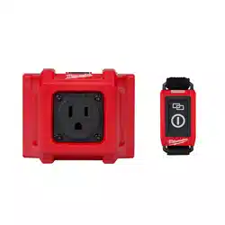
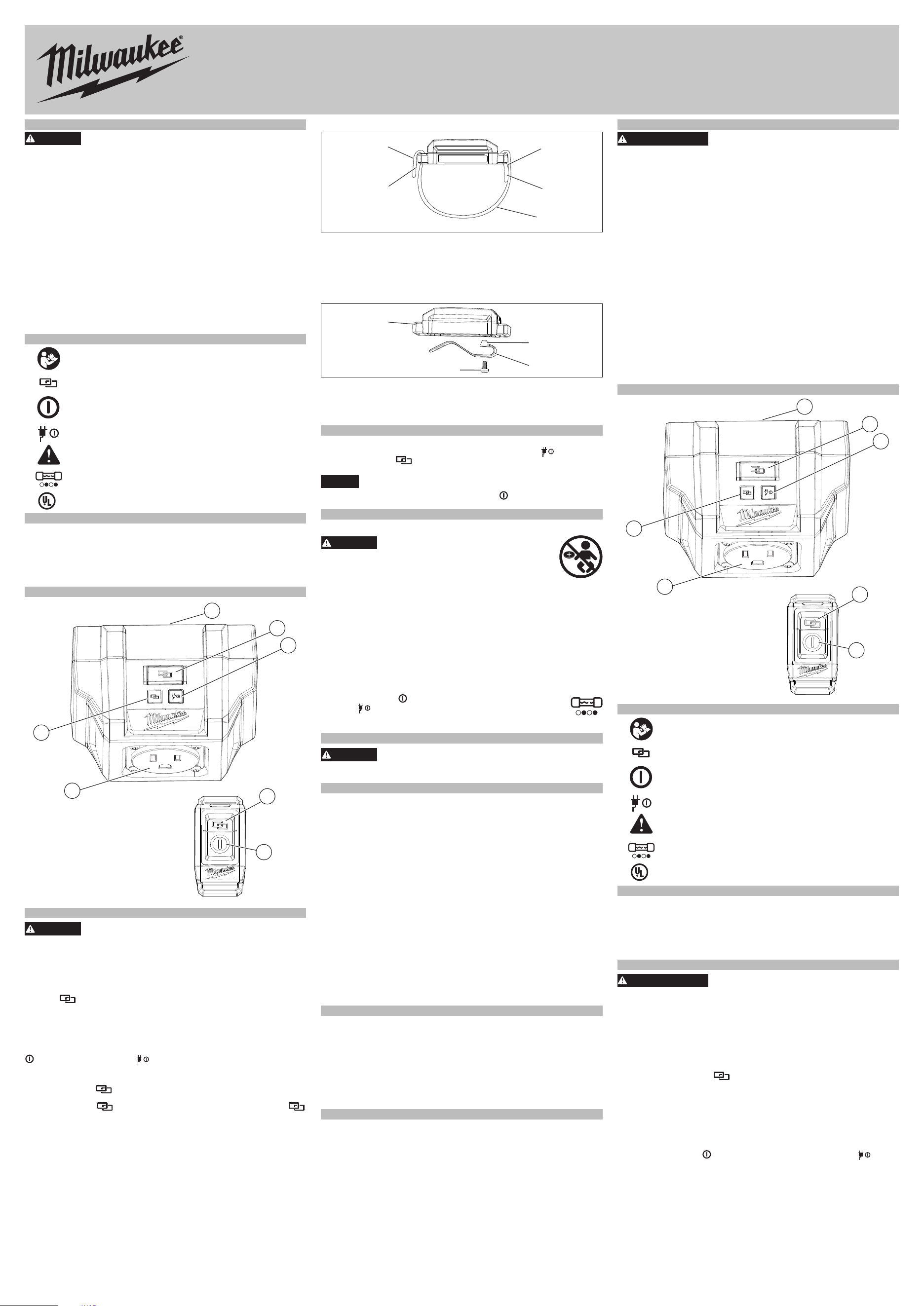
1. Male plug (not shown)
2. Pairing button
3. Power indicator
4. Pairing button
5. Power button
6. Outlet (Female Plug)
7. Pairing indicator
1
2
3
4
5
6
7
Cat. No. 0950-20
Cat. No. 0951-20
ASSEMBLY
WARNING
To reduce the risk of injury, always unplug tool before
changing or removing accessories. Only use acces-
sories specifically recommended for this tool. Others may be
hazardous.
Pairing
If remote is not connected to the adapter, pairing can be setup by:
1. Insert Adapter into an outlet. NOTE: To conrm the Adapter has power,
the power light indicator will light for 1 second.
2. Press button on the Adapter and the remote until both LED's begin
to ash. A steady green light on both Adapter and remote will conrm
that the unit is paired. NOTE: Remote needs to be within close proxim-
ity to ensure remote is receiving signal from the Adapter. This procedure
will time out in 30 seconds if tool is not paired and will enter standby
mode for inactivity.
To conrm that the remote has paired with the Adapter successfully, press
button on remote and the button will light. Multiple remotes can be
paired to one Adapter.
Unpairing
1. Press and hold button on remote until the LED has a ashing red
light.
2. Press and hold button on Adapter until the pairing indicator
LED has a ashing red light.
This procedure will time out in 30 seconds if remote and Adapter are not
paired. It will enter standby mode for user inactivity.
Remote Strap
Logo
Velcro
loop
Velcro
hook
Velcro
hook
Velcro
loop
Remote strap installation:
1. Feed logo side of strap through inner side of remote housing.
2. Fold strap over and press rmly.
3. Feed tail end of strap through the outer side of remote housing.
4. Fold strap over and press rmly.
To adjust the length of the strap, release velcro and pull snug.
Remote Belt Clip
Remote
Belt clip
Screw
Belt clip
tabs
1. To remove the belt clip, remove the screw from the back of the remote.
2. Pull the belt clip away from the remote.
3. To install the belt clip, line up the tabs on the clip with the notches on
the back of the remote.
4. Insert the screw and tighten securely.
GENERAL USE AND CARE
Use proper tools rated for this device. Others may be hazardous.
1. Insert Adapter into wall outlet. Conrm power indicator
ashes and
pairing indicator
is lit.
2. Plug corded tool into Adapter outlet.
NOTICE
Do not use with a tool that requires input current greater than
12 A. It could result in damage to the adapter.
3. Using remote, press the power button to turn ON/OFF tool.
NOTE: Ensure tool being used is ON and fully operational.
MAINTENANCE
Internal Remote Battery
WARNING
Chemical Burn Hazard. This device contains
a lithium button/coin cell battery. A new or
used battery can cause severe internal burns and lead to
death in as little as 2 hours if swallowed or enters the body.
Always secure the battery cover. If it does not close se-
curely, stop using the device, remove the batteries, and keep it away
from children. If you think batteries may have been swallowed or
entered the body, seek immediate medical attention.
An internal battery is used on the remote to facilitate full functionality.
To replace the battery:
1. Remove strap or the screw on the belt clip.
2. Remove the screw and open the battery door.
3. Remove the old battery, keep it away from children, and dispose of it
properly.
4. Insert the new battery (3V CR2032), with the positive side facing up.
5. Close the battery door and tighten the screw securely.
6. Reattach the strap or screw with belt clip.
Internal Fuse Failure
If the power button on the remote is pressed and the power
indicator starts ashing on the plug, there is an internal fuse
failure making the tool unusable. Please contact 1-800-SAWDUST
or visit milwaukeetool.com for service.
ACCESSORIES
WARNING
Use only recommended accessories. Others may be
hazardous.
For a complete listing of accessories, go online to www.milwaukeetool.
com or contact a distributor.
WIRELESS COMMUNICATION
Pursuant to part 15.21 of the FCC Rules, you are cautioned that changes
or modications not expressly approved by the party responsible for com-
pliance could void your authority to operate the product.
NOTE: This equipment has been tested and found to comply with the
limits for a Class B digital device, pursuant to part 15 of the FCC Rules.
These limits are designed to provide reasonable protection against harmful
interference in a residential installation. This equipment generates, uses
and can radiate radio frequency energy and, if not installed and used in
accordance with the instructions, may cause harmful interference to radio
communications. However, there is no guarantee that interference will
not occur in a particular installation. If this equipment does cause harmful
interference to radio or television reception, which can be determined by
turning the equipment o and on, the user is encouraged to try to correct
the interference by one or more of the following measures:
• Reorient or relocate the receiving antenna.
• Increase the separation between the equipment and receiver.
• Connect the equipment into an outlet on a circuit dierent from that to
which the receiver is connected.
• Consult the dealer or an experienced radio/ TV technician for help.
This device complies with part 15 of the FCC Rules and ISED-Canada's
license exempt RSS standards. Operation is subject to the following two
conditions: 1) This device may not cause harmful interference, and 2) This
device must accept any interference received, including interference that
may cause undesired operation.
SERVICE - UNITED STATES
1-800-SAWDUST (1.800.729.3878)
Monday-Friday, 7:00 AM - 6:30 PM CST
or visit www.milwaukeetool.com
Contact Corporate After Sales Service Technical Support with technical,
service/repair, or warranty questions.
Email: [email protected]
Become a Heavy Duty Club Member at www.milwaukeetool.com to receive
important notications regarding your tool purchases.
SERVICE - CANADA
Milwaukee Tool (Canada) Ltd
1.800.268.4015
Monday-Friday, 7:00 AM - 4:30 PM CST
or visit www.milwaukeetool.ca
DIRECTIVES DE SÉCURITÉ IMPORTANTES
AVERTISSEMENT
LIRE TOUS LES AVERTISSEMENTS DE
SÉCURITÉ ET INSTRUCTIONS EN VOUS
RÉFÉRANT AUX ILLUSTRATIONS DES BULLETINS FOURNIS
AVEC LE PRÉSENT ÉQUIPEMENT. Ne pas suivre toutes les instruc-
tions énumérées ci-dessous, pourrait causer un choc électrique, un in-
cendie et/ou des blessures graves. SAUVEGARDEZ CES INSTRUC-
TIONS - LE PRÉSENT MANUEL DU PROPRIÉTAIRE CONTIENT
DES INSTRUCTIONS DE FONCTIONNEMENT ET DE SÉCURITÉ
IMPORTANTES.
•Ne pas modier la che.
• Risque de brû-lure chimique. Gardez la batterie des cellules de hors
de la portée des enfants.
• Les ches des outils électriques doivent correspondre à la prise
secteur utilisée. Ne jamais modier la che, de quelque façon que
ce soit. Ne jamais utiliser d'adaptateurs de che avec des outils mis
à la terre. Les ches et prises non modiées réduisent le risque de choc
électrique.
• Éviter tout contact avec des surfaces mises à la terre comme des
tuyaux, des radiateurs, des cuisinières et des réfrigérateurs. Le risque
de choc électrique est accru lorsque le corps est mis à la terre.
• Ne pas exposer les outils électriques à l'eau ou l'humidité. La pénétra-
tion d’eau dans ces outils accroît le risque de choc électrique.
• Pour les travaux à l’extérieur, utiliser un cordon spécialement conçu à
cet eet. Utiliser un cordon conçu pour l'usage extérieur réduit les risques
de choc électrique.
• Si l’utilisation d’un outil électrique est inévitable dans un endroit
humide, utiliser une source d’alimentation munie d’un disjoncteur
de fuite de terre. L’utilisation d’un disjoncteur de fuite de terre réduit le
risque de choc électrique.
DESCRIPTION FONCTIONNELLE
1. Fiche mâle (non illustrée)
2. Bouton de couplage
3. Témoin d’alimentation
4. Bouton de couplage
5. Bouton d'alimentation
6. Sortie (che femelle)
7. Témoin de couplage
1
2
3
4
5
6
7
No. de cat. 0950-20
No. de cat. 0951-20
PICTOGRAPHIE
Lire le manuel d’utilisation
Couplage
Alimentation
Témoin d’alimentation
Risque de brû-lure chimique. Gardez la batterie des
cellules de hors de la portée des enfants.
Défaillance du fusible interne
C
US
UL Listing Mark pour Canada et États-unis
SPECIFICATIONS
No de Cat. l’adaptateur avec télécommande ...........................0950-20
Volts.
..............................................................................................120 CA
Ampéres ................................................................................................12
No de Cat. télécommande..........................................................0951-20
Type de batterie............................................................................CR2032
Module/FCC ID
.............................................................. BGM11S/QOQ11
Plage de communication
....................................... Jusqu’à 30,48m (100')
MONTAGE DE L'OUTIL
AVERTISSEMENT
Pour minimiser les risques de blessures, dé-
branchez toujours l’outil avant d’y faire des
réglages, d’y attacher ou d’en enlever les accessoires. L’usage
d’accessoires autres que ceux qui sont spéciquement recommandés
pour cet outil peut comporter des risques.
Couplage
Si la télécommande n’est pas connectée à l’adaptateur, il est possible de
congurer le couplage en suivant les étapes ci-dessous :
1. Brancher l’adaptateur à une prise. REMARQUE : Pour conrmer que
l’adaptateur a de l’alimentation, le témoin d’alimentation s’allumera
durant 1 seconde.
2. Appuyer sur le bouton de l’adaptateur et celui de la télécommande
jusqu’à ce que tous les deux témoins à DEL commencent à clignoter.
Un témoin en vert xe, sur l’adaptateur et la télécommande, vous lais-
sera savoir que l’unité est couplée. REMARQUE : Il faut que la télécom-
mande reste à une proximité immédiate, ceci an de garantir que la
télécommande puisse capter le signal de l’adaptateur. Cette procédure
sera interrompue après 30 secondes si l’outil n’est pas couplé et après,
passera en mode « veille » à cause de son inactivité.
Pour conrmer que la télécommande est bien couplée à l’adaptateur, ap-
puyer sur le bouton
de la télécommande et le bouton devra
s’allumer. Il est possible de coupler plusieurs télécommandes à un seul
adaptateur.
MILWAUKEE TOOL
13135 West Lisbon Road • Brookeld, WI 53005 USA
58220371d2 07/21
Printed in
01613100101Q-02(A)
Découplage
1. Appuyer, sans relâcher, sur le bouton de la télécommande jusqu’à
ce que le témoin à DEL s’allume en rouge clignotant.
2. Appuyer, sans relâcher, sur le bouton de l’adaptateur jusqu’à ce
que le témoin à DEL
de couplage s’allume en rouge clignotant.
Cette procédure sera interrompue après 30 secondes si la télécommande
et l’adaptateur ne sont pas couplés. L’appareil entrera en mode « veille »
à cause de l’inactivité de la part de l’utilisateur.
Sangle pour télécommande
Logotype
Boucle en
velcro
Crochet
en velcro
Crochet
en velcro
Boucle en
velcro
1. Faire entrer la sangle, du côté du logotype, à travers le côté interne de
la boîte de la télécommande.
2. Plier la sangle et appuyer fermement sur elle.
3. Faire entre le bout arrière de la sangle à travers le côté externe de la
boîte de la télécommande.
4. Plier la sangle et appuyer fermement sur elle.
Pour ajuster la longueur de la sangle, relâcher le velcro et tirer sur lui
fermement.
Clip de ceinture pour télécommande
Télécommande
Clip de
ceinture
Vis
Clip de
ceinture
onglets
1. Pour enlever le clip de la ceinture, retirez la vis de l’arrière de la télé-
commande.
2. Tirez le clip de la ceinture loin de la télécommande.
3. Pour installer le clip de la ceinture, alignez les onglets sur le clip avec
les encoches à l’arrière de la télécommande.
4. Insérez la vis et serrez-la solidement.
L’UTILISATION GÉNÉRALE ET LES SOINS
Utiliser les outils corrects dont la classication convient a cet appareil.
L’utilisation d’autres outils pourrait entrainer des situations dangereuses.
1. Brancher l’adaptateur à une prise murale. Vérier que le témoin
d’alimentation clignote et que le témoin de couplage est allumé.
2. Brancher l’outil raccordé à la prise de l’adaptateur.
AVIS
Ne pas utiliser avec un outil qui nécessite un courant d’entrée su-
périeur à 12 A. Cela pourrait endommager l’adaptateur.
3. Appuyer sur le bouton d’alimentation de la télécommande
pour
DÉMARRER / ARRÊTER l’outil. REMARQUE : Veuillez s’assurer que
l’outil utilisé est ALLUMÉ et fonctionne bien.
ENTRETIEN
Batterie Distante Interne
AVERTISSEMENT
Risque de brû-lure chimique. Ce
dis-positif contient une pile bouton
au lithium. Une pile neuve ou usée peut causer des
brûlures internes graves entraînant la mort en seulement
2 heures si avalée ou entrée dans le corps. Toujours xer
le couvercle du compartiment des piles. Si le couvercle ne se ferme
pas bien, arrêter d’utiliser le dispositif, retirer les piles et les garder
hors de la portée des enfants. Si vous soupçonnez que les piles ont
été avalées ou entrées dans le corps, consultez immédiatement un
médecin.
La télécommande se sert d’une bloc-piles interne pour permettre un
fonctionnement complet.
Pour remplacer le bloc-piles:
1. Enlever la sangle ou la vis du clip de ceinture.
2. Enlever la vis et ouvrir la porte du compartiment de bloc-piles.
3. Enlever la batterie usagée, la tenir hors de la portée des enfants et se
débarrasser d’elle de la manière correcte.
4. Mettre le nouveau bloc-piles (3V CR2032), avec le pôle positif vers le
haut.
5. Fermer la porte du compartiment de bloc-piles et bien serrer la vis.
6. Remettre la sangle ou la vis en place sur le clip de ceinture.
Défaillance du Fusible Interne
Si vous appuyez sur le bouton d’alimentation de la télécom-
mande et que le voyant lumineux commence à clignoter
sur la che, il y a une défaillance du fusible interne rendant l’outil
inutilisable. Veuillez communiquer avec 1-800-268-4015 ou visit-
ermilwaukeetool.ca pour le service.
ACCESOIRES
AVERTISSEMENT
L’utilisation d’autres accessoires que ceux qui
sont spéciquement recommandés pour cet
outil peut comporter des risques.
Pour une liste complète des accessoires, visiter le site internet
www.milwaukeetool.com ou contactez un distributeur.
COMMUNICATION SANS FIL
Conformément à la partie 15.21 des règles FCC, vous êtes averti que
les changements ou modications non expressément approuvés par la
partie responsable de la conformité pourraient annuler votre droit à utiliser
le produit.
REMARQUE : Après avoir eectué un essai à l’équipement, il a été
déterminé que celui-ci est conforme aux normes relatives à un appareil
numérique de classe B, selon la partie 15 des règles de la FCC. Ces
limites sont conçues pour assurer une protection raisonnable contre les
perturbations nuisibles dans une installation résidentielle. Cet équipement
produit, utilise et peut irradier une énergie haute fréquence et, s’il n’est
pas installé conformément aux présentes instructions, peut causer le
brouillage des communications radio. Toutefois, il n’existe aucune garantie
que le brouillage ne se produira pas dans une installation donnée. Si cet
équipement cause du brouillage de la réception d’émissions de radio ou
de télévision, ce qui peut être déterminé en l’éteignant et en le rallumant,
il est conseillé que l’utilisateur essaie de corriger le problème en prenant
l’une ou plusieurs des mesures suivantes :
• Réorientation de l’antenne réceptrice.
• Augmentation de la distance entre le matériel et le récepteur.
•Branchement du matériel sur un circuit autre que celui sur lequel le ré-
cepteur est branché.
•Consulter le concessionnaire ou un technicien radio/TV qualié pour
obtenir de l’aide.
Ce dispositif est conforme à la part 15 du Règlement de la FCC et les
normes RSS d’exemption de licence de l’ISED-Canada. Son fonctionne-
ment est soumis aux conditions suivantes : (1) Cet appareil ne doit pro-
duire aucun brouillage préjudiciable ; et (2) cet appareil doit fonctionner
en dépit de tout brouillage capté, y compris le brouillage pouvant mener
à un fonctionnement non désiré.
SERVICE - CANADA
Milwaukee Tool (Canada) Ltd
1.800.268.4015
Monday-Friday, 7:00 AM - 4:30 PM CST
www.milwaukeetool.ca
INSTRUCCIONES DE SEGURIDAD IMPORTANTES
ADVERTENCIA
LEA TODAS LAS ADVERTENCIAS, INSTRUC-
CIONES E ILUSTRACIONES DE SEGURIDAD
Y LAS ESPECIFICACIONES PROVISTAS CON ESTA HERRAMI-
ENTA ELÉCTRICA. No seguir todas las instrucciones que se enumeran
a continuación podría provocar una descarga eléctrica, incendio y/o le-
siones personales graves. GUARDE ESTAS INSTRUCCIONES - ESTE
MANUAL DEL OPERADOR CONTIENE INSTRUCCIONES IMPOR-
TANTES DE SEGURIDAD Y OPERACIÓN.
• No modique el enchufe.
• Riesgo de quem-adura química. Mantenga la batería de la celda de
monedas lejos de los niños.
• Los enchufes de la herramienta eléctrica deben coincidir con el
tomacorriente. Nunca modique el enchufe de ninguna manera. No
utilice adaptadores de enchufe con herramientas eléctricas ater-
rizadas. Los enchufes y tomacorrientes correspondientes sin modicar
reducirán el riesgo de descarga eléctrica.
• Evite el contacto corporal con supercies aterrizadas, tales como
tuberías, radiadores, estufas y refrigeradores. Existe un riesgo mayor
de descarga eléctrica si su cuerpo está aterrizado.
• No exponga las herramientas eléctricas a la lluvia ni a condiciones
húmedas. Si se introduce agua en una herramienta eléctrica, aumentará
el riesgo de descarga eléctrica.
• Al utilizar una herramienta eléctrica en exteriores, utilice una extensión
adecuada para uso en exteriores. El uso de una extensión adecuada
para el uso en exteriores disminuye el riesgo de descarga eléctrica.
• Si es inevitable utilizar una herramienta eléctrica en un lugar húmedo,
utilice un alimentador de corriente protegido con un interruptor de
circuito por falla de conexión a tierra (GFCI). El uso de un GFCI reduce
el riesgo de descarga eléctrica.
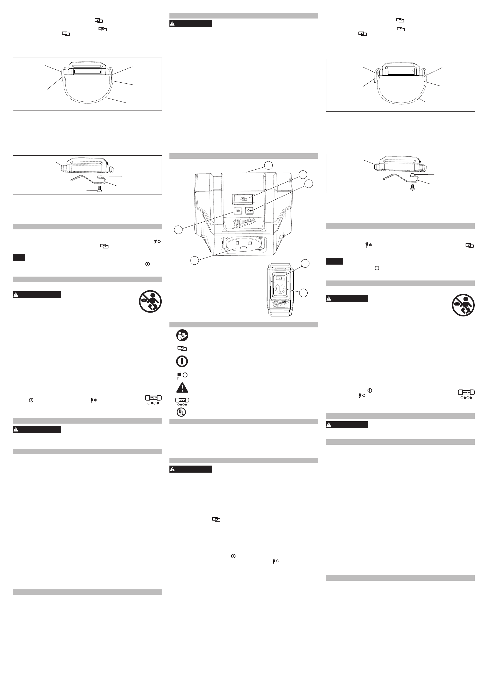
DESCRIPCION FUNCIONAL
1. Toma macho (no se muestra en la imagen)
2. Botón de acoplamiento
3. Indicador de alimentación
4. Botón de acoplamiento
5. Botón de encendido
6. Enchufe (toma hembra)
7. Indicador de acoplamiento
1
2
3
4
5
6
7
Cat. No. 0950-20
Cat. No. 0951-20
SIMBOLOGÍA
Leer el manual del operador
Acoplamiento
Alimentación
Indicador de alimentación
Riesgo de quem-adura química. Mantenga la batería de la
celda de monedas lejos de los niños.
Fallo del fusible interno
C
US
UL Listing Mark para Canadá y Estados Unidos
ESPECIFICADIONES
Cat. No. del adaptador con control remoto ..............................0950-20
Volts.
..............................................................................................120 CA
Amperios ...............................................................................................12
Cat. No. del control remoto.
......................................................0951-20
Tipo de batería
.............................................................................CR2032
Módulo/ID de FCC
......................................................... BGM11S/QOQ11
Rango de comunicación
...................................... De hasta 30,48m (100')
ENSAMBLAJE
ADVERTENCIA
Para reducir el riesgo de una lesión, desconecte
siempre la herramienta antes de jar o retirar
accesorios, o antes de efectuar ajustes. Utilice sólo los accesorios
especícamente recomendados. El uso de otros accesorios puede
ser peligroso.
Acoplamiento
Si el control remoto no está conectado al adaptador, es posible congurar
el acoplamiento al:
1. Conectar el adaptador a una toma de corriente. NOTA: Para conrmar
que el adaptador tiene energía, el indicador lumínico de alimentación
se encenderá durante 1 segundo.
2. Presione el botón del adaptador y el del control remoto hasta que
ambos indicadores LED empiecen a parpadear. Una luz verde ja en
el adaptador y en el control remoto conrmará que la unidad está aco-
plada. NOTA: Es necesario que el control remoto se mantenga cerca
para garantizar que reciba la señal del adaptador. Este procedimiento
se interrumpirá después de 30 segundos si la herramienta no se aco-
pla, por lo que entrará en modo de ahorro de energía debido a su inac-
tividad.
Para conrmar que el control
remoto está acoplado correctamente al
adaptador, presione el botón en el control remoto
y se encenderá el
botón. Es posible acoplar varios controles remotos a un solo adaptador.
Desacoplamiento
1. Mantenga presionado el botón en el control remoto hasta que el
indicador LED se encienda en rojo parpadeante.
2. Mantenga presionado el botón en el adaptador hasta que el in-
dicador LED
de acoplamiento se encienda en rojo parpadeante.
Este procedimiento se interrumpirá después de 30 segundos si el control
remoto y el adaptador no están acoplados. Entrará en modo de ahorro de
energía debido a la inactividad de parte del usuario.
Correa para control remoto
Logotipo
Arillo de
velcro
Gancho de
velcro
Gancho
de velcro
Arillo de velcro
1. Meta el lado de la correa que tiene el logotipo en el lado interno de la
carcasa del control remoto.
2. Doble la correa y apriete con rmeza.
3. Meta el extremo nal de la correa en el lado externo de la carcasa del
control remoto.
4. Doble la correa y apriete con rmeza.
Para ajustar la longitud de la correa, suelte el velcro y ajústelo.
Gancho para cinturón para control remoto
Control remoto
Gancho para
cinturón
Tornillo
Gancho
para
cinturón
pestañas
1. Para quitar el clip de la correa, retire el tornillo de la parte posterior
del mando a distancia.
2. Tire del clip de la correa lejos del mando a distancia.
3. Para instalar el clip de la correa, alinee las pestañas del clip con las
muescas en la parte posterior del mando a distancia.
4. Inserte el tornillo y apriete rmemente.
USO GENERAL Y CUIDADO
Utilice las herramientas adecuadas que se ajusten a las características de
este dispositivo. Utilizar otras herramientas podrá ser peligroso.
1. Conecte el adaptador a una toma de corriente de pared. Asegúrese de
que el indicador
de alimentación parpadee y que el indicador
de acoplamiento esté encendido.
2. Conecte la herramienta alámbrica a la toma del adaptador.
AVISO
No utilizar con una herramienta que requiera corriente de en-
trada superior a 12 A. Podría resultar en daños en el adaptador.
3. Presione el botón de encendido en el control remoto para
ENCENDER/APAGAR la herramienta. NOTA: Asegúrese de que la
herramienta a utilizar esté encendida y funcione correctamente.
MANTENIMIENTO
Batería Remota Interna
ADVERTENCIA
Riesgo de quem-adura química. Este
dispositivo contiene una batería de
botón/tipo moneda de litio. Una batería nueva o usada
puede causar quemaduras internas graves y causar la
muerte tan solo en 2 horas si se ingiere o entra al cuerpo.
Siempre asegure la cubierta de la batería. Si no se cierra con rmeza,
deje de usar el dispositivo, retire las baterías y manténgala alejada
de los niños. Si cree que las baterías pudieron ser ingeridas o entraron
al cuerpo, busque atención médica de inmediato.
El control remoto utiliza una batería interna para permitir el uso pleno de
las funcionalidades.
Para cambiar la batería:
1. Quite la correa o el tornillo del gancho para cinturón.
2. Quite el tornillo y abra la puerta de la batería.
3. Retire la batería anterior, manténgala lejos del alcance de los niños y
deshágase de ella de la manera correcta.
4. Coloque la nueva batería (3V CR2032), con el lado positivo hacia arriba.
5. Cierre la puerta de la batería y apriete bien el tornillo.
6. Vuelva a jar la correa o el tornillo al gancho para cinturón.
Fallo del Fusible Interno
Si se pulsa el botón de encendido del mando a distancia y la
luz indicadora comienza a parpadear en el enchufe, se
produce un fallo interno del fusible que hace que la herramienta
sea inutilizable. Por favor, póngase en contacto con 01 (800) 030-7777 o
(55) 4160-3540 o visita milwaukeetool.com.mx para el servicio.
ACCESORIOS
ADVERTENCIA
Utilice sólo los accesorios especícamente reco-
mendados. Otros accesorios puede ser peligroso.
Para una lista completa de accessorios, visite nuestro sitio en Inter-
net: www.milwaukeetool.com o póngase en contacto con un distribuidor.
COMUNICACIÓN INALÁMBRICA
De conformidad con la parte 15.21 de las Reglas de la FCC, se le advi-
erte que los cambios o modicaciones no aprobados expresamente por
la parte responsable del cumplimiento podrían anular su autoridad para
operar el producto.
NOTA: Este equipo ha sido probado y se ha encontrado que cumple
con los límites de un dispositivo digital de Clase B, en cumplimiento con
la parte 15 de las reglas de la FCC. Estos límites están diseñados para
proporcionar protección razonable contra la interferencia nociva en una
instalación residencial. Este equipo genera, usa y puede irradiar energía
de radiofrecuencia y, si no se instala y se utiliza de acuerdo con las instruc-
ciones, puede ocasionar interferencia nociva con las comunicaciones por
radio. Sin embargo, no existe garantía de que no ocurrirá interferencia en
una instalación en particular. Si este equipo ocasiona interferencia nociva
con la recepción de radio o televisión que pueda determinarse encendiendo
y apagando el equipo, se anima al usuario a intentar corregir la interferencia
mediante una o más de las siguientes medidas:
• Reorientar o reubicar la antena receptora.
• Aumentar la distancia entre el equipo y el receptor.
• Conectar el equipo a un tomacorriente que esté en un circuito diferente
a donde está conectado el receptor.
•Consulte al distribuidor o a un técnico experimentado de radio/TV para
solicitar ayuda
Este dispositivo cumple con la parte 15 de las normas de la FCC y los
estándares RSS exentos de licencia de ISED-Canada. La operación está
sujeta a las siguientes dos condiciones: (1) este dispositivo no debe oca-
sionar interferencia nociva y (2) este dispositivo debe aceptar cualquier
interferencia que se reciba, incluyendo la interferencia que pueda ocasionar
operación indeseada.
SOPORTE DE SERVICIO - MEXICO
CENTRO DE ATENCION A CLIENTES
Techtronic Industries Mexico, S.A. de C.V.
Av. Presidente Masarik 29 Piso 7
11560 Polanco V Seccion
Miguel Hidalgo, Distrito Federal, México
01 (800) 030-7777 o (55) 4160-3540
Lunes a Viernes (9am a 6pm)
O contáctanos en www.milwaukeetool.com.mx
