
Loading ...
Loading ...
Loading ...
9Section 2 — ASSembly & Set-Up
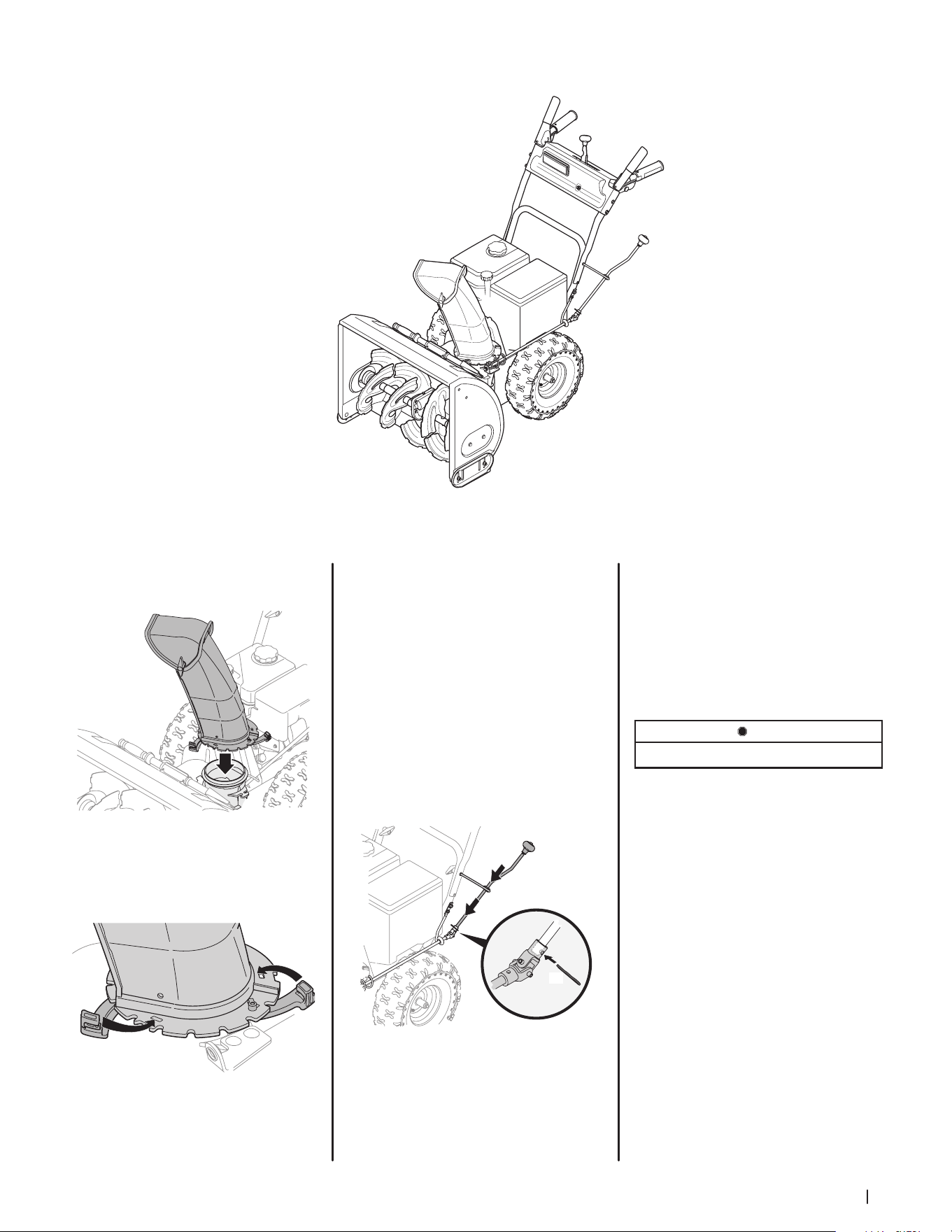
U-Joint Side Crank Chute Control
Figure 2-16
1. Position chute assembly over base.
See Figure 2-17.
Figure 2-17
2. Close flange keepers to secure chute
assembly to chute base. Flange keepers
will click into place when properly
secure. See Figure 2-18.
Figure 2-18
NOTE: Ensure the lower chute is secured
to the flange on the chute base. The
lower edge of the chute keeper should
be positioned below the flange on the
chute base after being clicked into place.
If flange keepers will not easily click into
place, use palm of your hand to apply
swift, firm pressure to the back of each.
Chute Directional Control Assembly
1. Remove cotter pin from end of
unattached chute directional control
assembly.
2. Insert unattached chute directional
control assembly into eye bolt on left
side of handle assembly. See Figure 2-19.
(a)
Figure 2-19
3. Line up holes in the end of unattached
chute directional control assembly
with holes in U-joint attached to lower
chute directional control assembly.
Insert cotter pin (a). See Figure 2-19. If
necessary, bracket securing lower chute
directional control assembly to chute
base can be adjusted. Refer to Chute
Bracket Adjustment in Service section
on page 25.
STOP
Continue to Set-Up (page 14).
Loading ...
Loading ...
Loading ...