Loading ...
Loading ...
Loading ...
13Section 2 — ASSembly & Set-Up
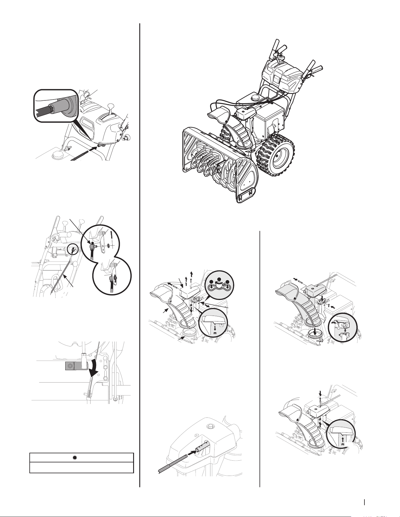
5. Insert flex shaft (b) removed during
Handle Assembly from lower handle
into rear of chute directional control
head. See Figure 2-37. Secure flex shaft
to chute control head with hairpin clip
(a) removed in Step 4.
6. Insert hex end of flex shaft into chute
control rod coupling under dash panel.
See Figure 2-38.
Figure 2-38
7. Ensure speed selector is in fastest
forward speed.
8. Remove cotter pin (a) and washer (b)
from ferrule on end of shift rod.
See Figure 2-39 inset.
(a)
(b)
Shift Rod
Ferrule
Figure 2-39
9. Make sure the shift lever on the back of
the transmission is rotated downward to
the full extent of its rotation. See Figure
2-40.
Figure 2-40
10. Insert ferrule into top hole of shift
lever and secure with cotter pin (a) and
washer (b) removed in Step 8. See Figure
2-39. Ferrule may need to be adjusted
up or down.
STOP
Continue to Set-Up (page 14).
Electric Chute Control
Figure 2-41
1. Remove cotter pin (a), wing nut (b) and
hex screw (c) from chute control head.
Remove clevis pin (d) and bow-tie cotter
pin (e) from chute support bracket.
See Figure 2-42.
(c)
(e)
1
1
2
Chute
Chute
Support
Bracket
Chute Base
(a)
(d)
(b)
Chute
Control Head
Figure 2-42
NOTE: For smoothest operation, cables should
all be to the left of the chute directional
control rod.
2. Insert round end of chute control rod
into chute control head. Push rod as
far into chute control head as possible,
keeping holes in rod pointing upward.
See Figure 2-43.
Figure 2-43
3. Place chute onto chute base and ensure
chute control rod is positioned under
handle panel. Secure chute control head
to chute support bracket with
clevis pin (d) and bow-tie cotter pin (e)
removed in Step 1. See Figure 2-44.
(d)
(e)
Figure 2-44
4. Finish securing chute control head by
installing hex screw (c) and wing nut (b)
removed in Step 1. See Figure 2-45.
(c)
(b)
Figure 2-45
Loading ...
Loading ...
Loading ...