Loading ...
Loading ...
Loading ...
6 Section 2 — ASSembly & Set-Up
Tools Required
• Adjustable Wrench or Socket Set
• Needle Nose Pliers
Handle Assembly
Refer to Figure 2-1 and proceed to your
applicable chute style.
All units except those equipped with E-Z
Chute™
1. Cut cable ties securing chute control rod
or upper handle to the lower handle (if
applicable), set aside the chute control
rod (if applicable) and remove the wrap
around the handles (if applicable).
NOTE: Do not cut the cable tie securing the
cables to the engine for units equipped.
NOTE: On units with Overhead Chute
Control (with Flex Shaft), Four-Way Chute
Control, and Electric Chute Control
cut cable ties securing flex shaft to the
lower handle and set the flex shaft aside.
Remove rubber bands securing cables to
carriage screws and cut cable tie securing
shift rod to lower handle. Refer to Figure
2-1 to help identify your unit.
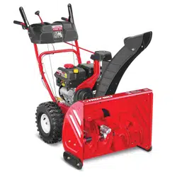
2. Loosen the top two nuts (a) securing the
upper and lower handle and remove the
two carriage screws (b) from the lower
handle and set aside as shown in Figure
2-2 or Figure 2-3 for units with side
supports.
(a)
(a)
(b)
(b)
Figure 2-2
(a)
(a)
(b)
(b)
Figure 2-3
3. Place shift lever in Forward-6 position or
fastest forward speed (if equipped).
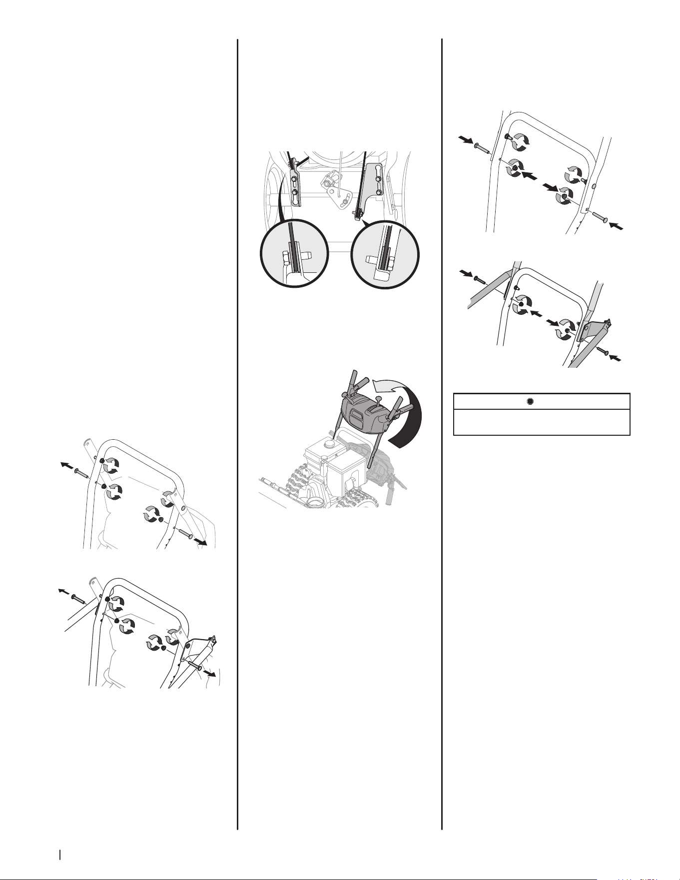
4. Observe lower rear area of equipment
to be sure both cables (if equipped) are
aligned and seated properly in roller
guides. See Figure 2-4.
NOTE: On select units, chute-pitch control
cables will be routed under the engine on the
left side and will not use roller guides.
Figure 2-4
5. Pivot handle upward and align the lower
handle. See Figure 2-5. Remove and
discard any rubber bands, if present.
They are for packaging purposes only.
Figure 2-5
NOTE: On select units with steel rod
speed selectors, you may need to lower
shift rod to the side slightly to maneuver
handle panel over it when pivoting
handle upward.
6. Attach the two carriage screws (b)
and nuts (a) removed in Step 2. Finish
securing the handle by tightening the
top two nuts (c) loosened in Step 2. See
Figure 2-6 or Figure 2-7 for units with
side supports.
(c)
(c)
(b)
(b)
(a)
(a)
Figure 2-6
(c)
(c)
(a)
(a)
(b)
(b)
Figure 2-7
STOP
Refer to Figure 1 to identify your applicable chute style
and continue to Chute Assembly Options (page 7).
Loading ...
Loading ...
Loading ...