
Loading ...
Loading ...
Loading ...
7Section 2 — ASSembly & Set-Up
IMPORTANT: It will be necessary to lift
the upper handle (b) while sliding up
this cable tie to prevent damage to the
cable.
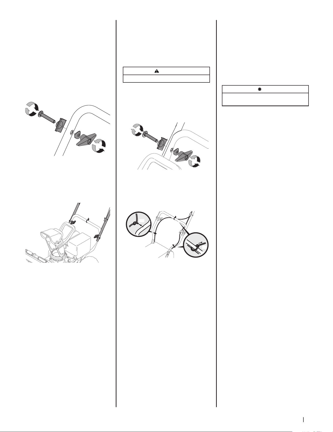
4. Lift the upper handle (b) up and position
it over the lower handle (c), aligning
the holes where the wing knobs were
removed. See Figure 2-9.
CAUTION
Be careful not to bend or kink the cables.
Insert a carriage screw (a) from the outside
through a handle tab (b), the upper (c) and
lower handles (d), a saddle washer (e) and into
the wing knob (f). Repeat on the other side.
Tighten the wing knobs (f) on each side of the
handle. Refer to Figure 2-10.
(c)
(e)
(b)
(a)
(d)
(f)
Figure 2-10
NOTE: The auger cable (a) routes down the
left lower handle and the drive cable (b) is
routed across the top of the lower handle
and down the right side of the lower handle.
See Figure 2-11.
(c)
(d)
(c)
(b)
(a)
(c)
(d)
Figure 2-11
5. Two cable ties (c) have been used to
loosely tie the control cables to the lower
handle, including the cable tie (c) you
relocated in step 3. A push clip (d) is also
included on the lower drive cable (b).
Position cable ties (c) now, as in Figure
2-11, and tighten to secure cables (a &
b) to the lower handle. Trim off excess
material of cable ties (c). If not already
installed, push the clip (d) on the drive
cable (b) into the hole in the handle
provided as shown in the left inset.
STOP
Refer to Figure 2-1 to identify your applicable chute
style and continue to Chute Assembly Options (page 7).
Chute Assembly Options
Refer to Figure 2-1 and proceed to your
applicable Chute Control Style on pages 8-14.
E-Z Chute
1. Remove cable tie (if present) securing
upper handle to lower handle for
shipping purposes. Remove all
protective plastic wrapping from
handles.
NOTE: Be careful NOT to remove the
two loosely fitted cable ties that will be
utilized later to secure cables.
2. Remove the wing knob (a), saddle
washer (b), handle tab (c) and carriage
screw (d) on each side of the lower
handle. See Figure 2-8.
(c)
(b)
(a)
(d)
Figure 2-8
3. Slide one of the loosely fitted cable
ties (a) from the right side of the lower
handle (c) up to the cross member of the
lower handle (c). Leave the second cable
tie in place on the right side of the lower
handle (c). See Figure 2-9.
(c)
(b)
(a)
Figure 2-9
Loading ...
Loading ...
Loading ...