Loading ...
Loading ...
Loading ...
25Section 4 — Product care
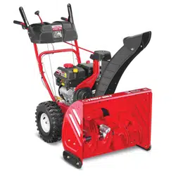
Auger Shaft
At least once a season, remove shear pins (a)
and cotter pins (b) from auger shaft(s). Spray
lubricant inside shaft and around spacers and
flange bearings found at either end of shaft(s).
See Figure 4-6.
(a)
(a)
(b)
(b)
NOTE: Three Stage
Augers Shown
(a)
(b)
Figure 4-6
IMPORTANT:
On 3-stage units, there
is an additional shear pin in the rear
accelerator.
Adjustments
Shift Rod (If Equipped)
Refer to Shift Rod on page 17 for instructions
on adjusting shift rod.
Shift Cable (If Equipped)
Refer to Shift Cable on page 16 for instructions
on adjusting shift cable.
Auger Control (IF Equipped)
Refer to Auger Control on page 16 for
instructions on adjusting auger control cable.
Drive Control (If Equipped)
Refer to Drive Control on page 17 for
instructions on adjusting drive control cable.
Skid Shoes
Refer to Assembly & Set-up section (page 15)
for instructions on adjusting skid shoes.
Chute Bracket (If Equipped)
If spiral at bottom of the chute directional
control is not fully engaging with chute
assembly, chute bracket needs to be adjusted.
To do so:
1. Loosen two nuts (a) which secure chute
bracket and reposition it slightly. See
Figure 4-7.
Standard
U-Joint
(a) (a)
Figure 4-7
2. Retighten nuts.
Chute Control Rod (Two Way & Four Way
Chute Control) (If Equipped)
To adjust chute control rod for increased
engagement into the handle panel control,
proceed as follows:
1. Remove hairpin clip (a) from hole closest
to chute assembly on chute rotation
assembly.
2. Pull out chute control rod until hole in
it lines up with second hole in chute
rotation assembly. See Figure 4-8.
(a)
Figure 4-8
3. Reinsert hairpin clip (a) through this hole
and chute control rod.
Chute Assembly/E-Z Chute™
Refer to Assembly & Set-up section (page
15) for instructions on adjusting chute
assembly/E-Z Chute™.
Chute Assembly (Overhead Chute Control)
(If Equipped)
If chute fails to remain stationary during
operation, pre-load of chute can be adjusted
by tightening hex nut found on front of chute
control assembly.
1. To increase preload, tighten
hex nut (a) clockwise in ¼ turn intervals.
The chute control rod will need to be
held stationary when tightening the nut.
See Figure 4-9.
(a)
Figure 4-9
2. If chute directional control is difficult to
crank, decrease preload by loosening
hex nut counter-clockwise in ¼ turn
intervals.
Service
Auger Belt Replacement (500, 600 and
800 Series)
To remove and replace auger belt, proceed as
follows:
1. Allow engine to run until it is out of
fuel. Do not attempt to pour fuel from
engine.
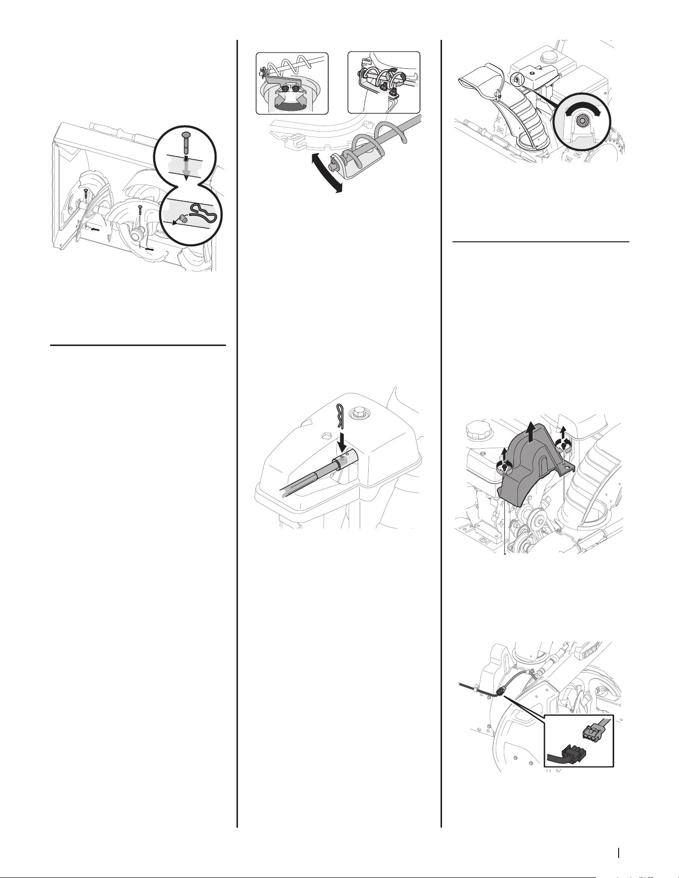
2. Remove plastic belt cover on front of
engine by removing two self-tapping
screws (a). See Figure 4-10.
(a)
(a)
Figure 4-10
NOTE: On models equipped with
the LED light bar on top of the auger
housing, make sure to unplug the wire
harness before removing the belt cover
as shown in Figure 4-11.
Figure 4-11
Loading ...
Loading ...
Loading ...