Loading ...
Loading ...
Loading ...
20 Section 3 — controlS & operation
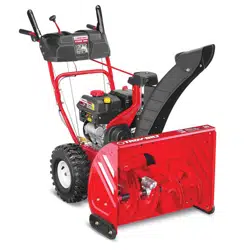
Drive Control Lever/Auger Clutch
Lock* (If Equipped)
The drive control lever is located on the right
handle. Squeeze the control lever against the
handle to engage the wheel drive. Release to
stop. See Figure 3-5.
Figure 3-5
*On select models, the drive control lever also
locks the auger control lever so that you can
operate the chute directional control without
interrupting the snow throwing process. If the
auger control lever is engaged simultaneously
with the drive control lever, the operator can
release the auger control lever (on the left
handle) and the augers will remain engaged.
Release both control levers to stop augers and
wheel drive.
NOTE: Always release drive control lever
before changing speeds on all units except the
800-series hydro. Failure to do so will result
in increased wear on your machine’s drive
system.
Drive Control Bail (If Equipped)
Located on the underside of the upper handle,
the drive control bail is used to engage/
disengage wheels. Squeeze the drive control
bail against the upper handle to engage the
wheels; release to disengage.
Auger Control Bail (If Equipped)
The auger control bail is adjacent to the upper
handle. Squeeze the auger control bail against
the upper handle to engage the augers;
release to disengage the augers.
IMPORTANT: Refer to the Auger Control
information in the Assembly & Set-Up section
prior to operating your snow thrower. Read
and follow all instructions carefully and
perform all adjustments to verify your snow
thrower is operating safely and properly.
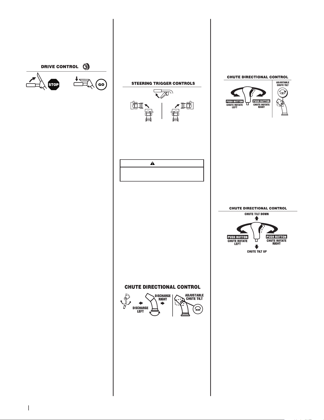
Steering Trigger Controls
(If Equipped)
The left and right wheel steering trigger
controls are located on the underside of the
handles. Refer to Figure 3-6.
IMPORTANT: Units with Hydro Transmission
- When moving the unit without starting the
engine, squeeze both right and left triggers to
disengage the drive.
Figure 3-6
• Squeeze the right trigger control to turn
right.
• Squeeze the left trigger control to turn
left.
CAUTION
Operate the snow thrower in open areas until you are
familiar with these controls.
Standard/U-Joint Chute
Directional Control (If Equipped)
The standard/U-Joint chute directional control
is located on the left side of the unit. To change
direction in which snow is thrown, rotate chute
directional control. See Figure 3-7.
Overhead Chute Directional
Control (If Equipped)
The overhead chute directional control
is located at the rear of the snow thrower
towards the left side of the unit under the
handle panel. To change the direction in
which snow is thrown, rotate chute directional
control. See Figure 3-7.
Figure 3-7
2-Way Chute Directional Control
Joystick (If Equipped)
The 2-Way chute directional control joystick is
located on the left side of the dash panel.
• To change direction in which snow is
thrown, squeeze button on joystick and
pivot joystick to right or to the left. See
Figure 3-8.
Figure 3-8
4-Way Chute Directional Control
Joystick (If Equipped)
The 4-Way chute directional control joystick is
located on the left side of the dash panel.
• To change the direction in which snow
is thrown, squeeze the button on the
joystick and pivot the joystick to the
right or to the left. See Figure 3-9.
• To change the angle/distance which
snow is thrown, pivot the joystick
forward or backward.
Figure 3-9
Loading ...
Loading ...
Loading ...