Loading ...
Loading ...
Loading ...
26 Section 4— Product care
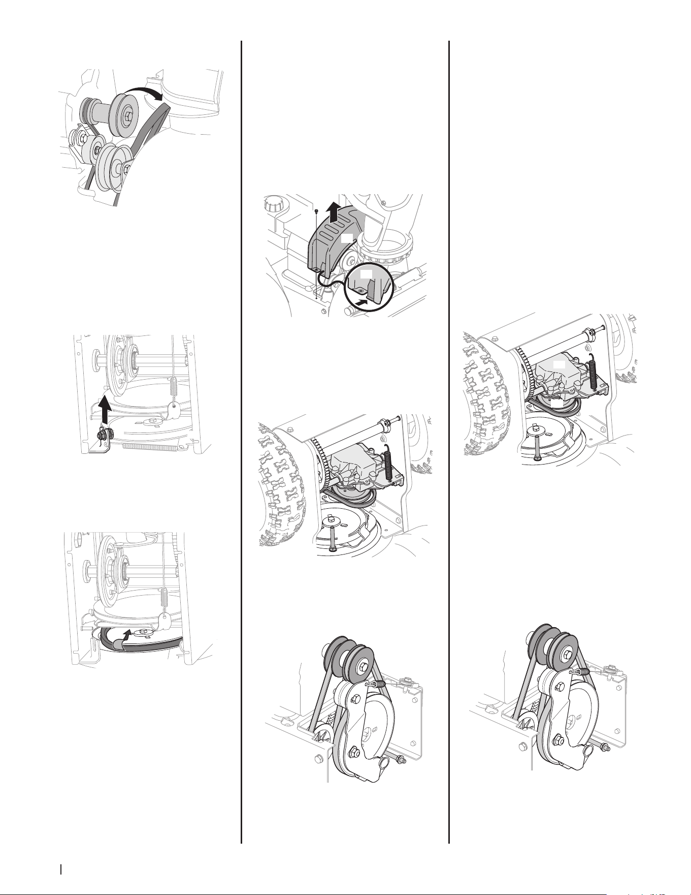
3. Roll auger belt off engine pulley.
See Figure 4-12.
Figure 4-12
4. Carefully pivot the unit up and forward
so that it rests on the auger housing.
5. Remove frame cover from underside of
unit by removing self-tapping screws
which secure it. See Figure 4-4.
6. Loosen and remove shoulder bolt (a) which
acts as a belt keeper and unhook the spring
(b) from the frame. See Figure 4-13.
NOTE: Multi-speed unit shown.
(a)
(b)
Figure 4-13
7. Remove belt from around auger pulley,
and slip it between support bracket and
auger pulley. See Figure 4-14.
Figure 4-14
NOTE: Engaging auger control will ease
removal and reinstallation of belt.
8. Replace auger belt by following
instructions in reverse order.
NOTE: Make sure to reinstall shoulder
bolt (a) and reconnect spring to frame
after installing a replacement auger belt.
Refer to Figure 4-13.
9. After replacing auger belt, perform
Auger Control test in Assembly & Set-Up
section (page 16).
Auger Belt Replacement (300 Series)
1. Allow the engine to run until it is out of
fuel. Do not attempt to pour fuel from
the engine.
2. Remove the safety key to prevent
accidental starting.
3. Remove the self-tapping screw (a)
shown in Figure 4-15, and press the
plastic tabs (b) to release the belt cover
(c). Pull the belt cover (c) up and out
from around the engine and chute
assembly. Set it aside and save.
(a)
(c)
(b)
Figure 4-15
4. Tip the snow thrower up and forward
so that it rests on the auger housing.
Remove the belt keeper (a). See Figure
4-16. Return the snow thrower to
its upright position to complete the
following steps.
(a)
Figure 4-16
5. Slip the front auger belt (a) off of the
engine pulley (b), pushing it forward
and rolling in off of the engine pulley
(b). See Figure 4-17.
(a)
(b)
Figure 4-17
6. Squeeze the auger control bail to
release the auger brake, which is the
tab that holds the belt onto the auger
pulley. Remove the belt.
7. Replace auger belt by following
instructions in reverse order.
8. After replacing auger belt, perform
Auger Control test in Assembly & Set-Up
section (page 16).
Drive Belt Replacement (500, 600 and
800 Series)
NOTE: See your authorized service dealer to
have drive belt replaced or contact Customer
Support.
Drive Belt Replacement (300 Series)
1. Remove the auger belt as instructed on
page 26.
2. Remove the spring (a) that connects the
transmission to a bolt on the engine
frame. See Figure 4-18.
(a)
(c)
(b)
(d)
Figure 4-18
NOTE: It may be easier to first remove
the flange lock nut, then use needle-
nosed pliers to firmly grip spring and
remove from bolt.
3. Pivot the transmission (b) forward to
release pressure on the drive belt (c).
Remove drive belt (c) from transmission
pulley (d).
4. Remove the drive belt (a) from around
the engine pulley (b), and away from the
unit. See Figure 4-19.
(a)
(b)
Figure 4-19
Loading ...
Loading ...
Loading ...