Loading ...
Loading ...
Loading ...
8.2 Trigger Level
The adjustment of the trigger level/threshold level is related to the type of the trigger
source.
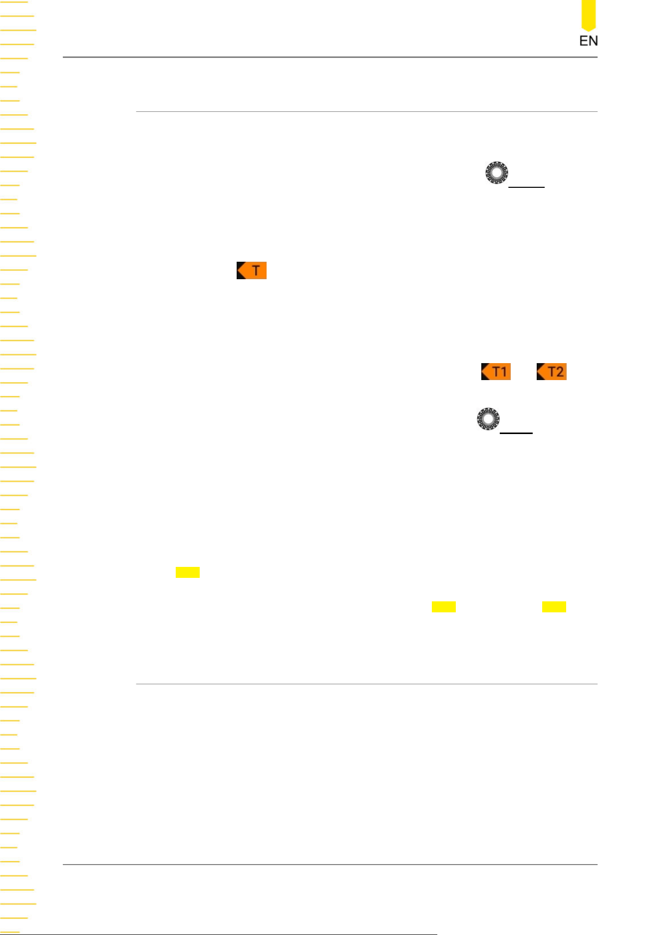
• When the trigger source is CH1-CH4, rotate the front-panel
LEVEL knob or
use the corresponding multipurpose knob (when the trigger menu is opened) to
adjust the trigger level. You can also click or tap the Level input field to set the
value with the pop-up numeric keypad. During the adjustment, a trigger level
line (the color of the trigger level line is the same as that of the channel) and a
trigger icon " " are displayed on the screen, and they move up and down
with the variation of the trigger level. When you stopping modifying the trigger
level, the trigger level line disappears in about 2 s. The current trigger level is
displayed in the trigger information label at the top of the screen.
In Runt Trigger, Slope Trigger, and Window trigger, you need to set the upper
and lower limits of the trigger level. Two trigger level icons and are
displayed at the right section of the screen.
• When the trigger source is D0-D15, rotate the front-panel
LEVEL knob or
use the corresponding multipurpose knob (when the trigger menu is opened) to
adjust the threshold level. You can also click or tap the input field to set the
value with the pop-up numeric keypad. In addition, you can set the threshold
level for digital channels in the LA menu as shown in
Figure 12.1
. For details,
refer to
To Set the Threshold
. The current threshold level is displayed in the
trigger information label at the top of the screen.
To better trigger the waveforms, for a trigger with a single level, you can directly click
or tap
50% in the menu or press the trigger level knob to make the level move to the
middle of the waveform. However, for a trigger with two levels (e.g. Slope trigger,
Runt trigger, Window trigger), you need to click or tap
90% for Level A and 10% for
Level B to make the level move within the range of the waveform amplitude.
8.3 Trigger Mode
The following is the schematic diagram of the acquisition memory. To better
understand the trigger event, you can think of the trigger event as dividing
acquisition memory into a pre-trigger and post-trigger buffer.
Triggering the Oscilloscope
DHO900 User Guide
62
Copyright ©RIGOL TECHNOLOGIES CO., LTD. All rights reserved.
Loading ...
Loading ...
Loading ...