Loading ...
Loading ...
Loading ...
5.4 To Specify Channel Coupling
You can remove unwanted signals by setting the coupling mode. For example, the
signal under test is a square waveform with DC offset.
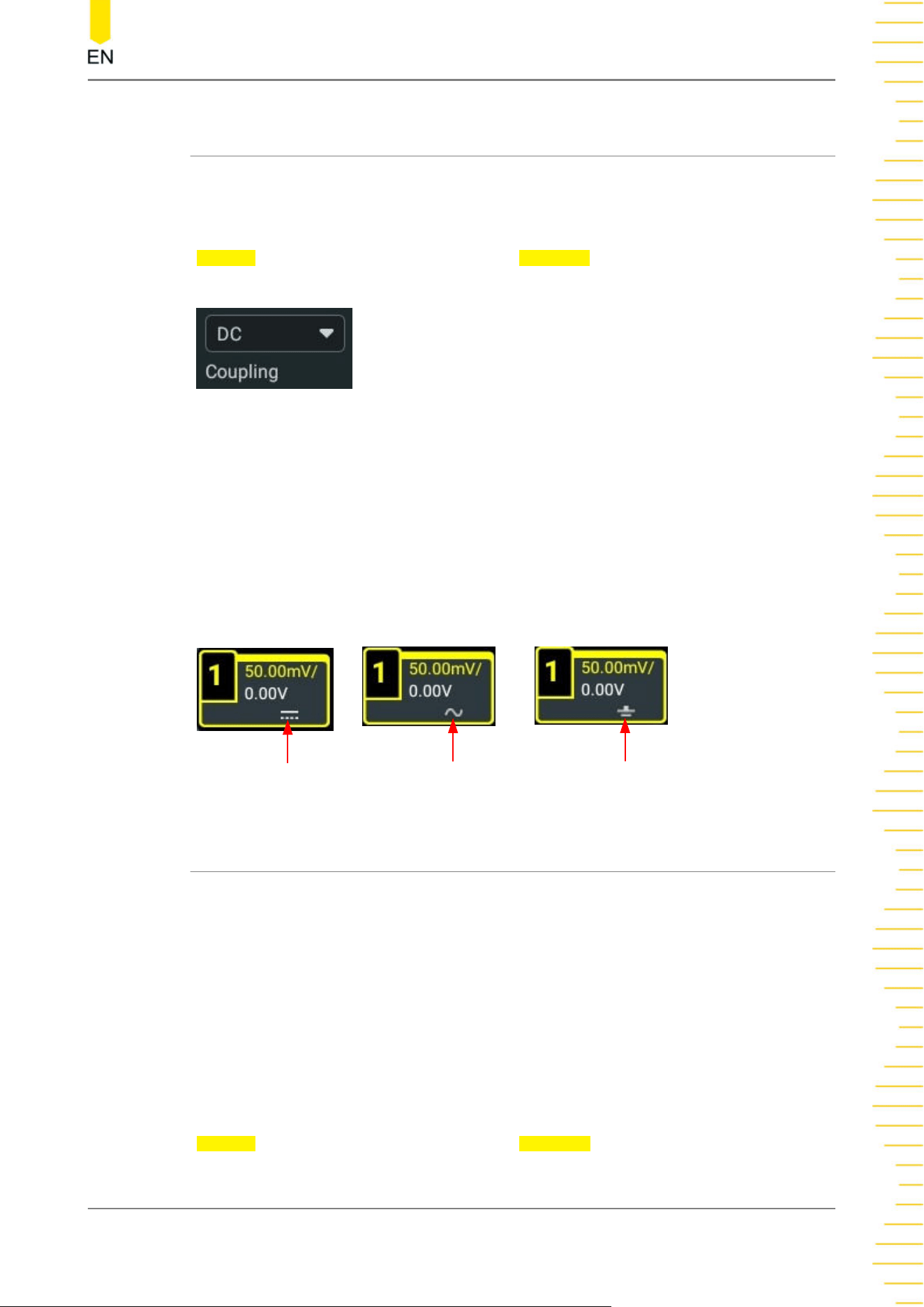
Click or tap the channel status label at the bottom of the screen, and then the
Vertical menu is displayed. Click or tap the Coupling drop-down button to select the
coupling mode.
• When the coupling mode is "DC", both the DC and AC components of the signal
under test can pass the channel.
• When the coupling mode is "AC", the DC components of the signal under test
are blocked
• When the coupling mode is "GND", the DC and AC components of the signal
under test are blocked.
After a coupling mode is selected, it is indicated in the channel status label at the
bottom of the screen, as shown in the figure below.
GND
AC
DC
5.5 To Specify Bandwidth Limit
This oscilloscope supports the bandwidth limit function. Setting the bandwidth limit
can reduce the noises in the displayed waveforms. For example, the signal under test
is a pulse with high frequency oscillation.
• When the bandwidth limit is turned off, the high frequency components of the
signal under test can pass the channel.
• When the bandwidth limit is turned on, the high frequency components found in
the signal under test that are greater than the limit are attenuated. This series
supports 20 MHz bandwidth limit.
Click or tap the channel status label at the bottom of the screen, and then the
Vertical menu is displayed. Click or tap the BW Limit drop-down button to select the
specified bandwidth. When the bandwidth limit is enabled, the specific bandwidth
Vertical System
Copyright ©RIGOL TECHNOLOGIES CO., LTD. All rights reserved. DHO900 User Guide
41
Loading ...
Loading ...
Loading ...