
33PC GLOW PLUG THREAD REPAIR SET
MODEL NO: VS311.V2
Thank you for purchasing a Sealey product. Manufactured to a high standard, this product will, if used according to these instructions,
and properly maintained, give you years of trouble free performance.
IMPORTANT: PLEASE READ THESE INSTRUCTIONS CAREFULLY. NOTE THE SAFE OPERATIONAL REQUIREMENTS, WARNINGS & CAUTIONS. USE
THE PRODUCT CORRECTLY AND WITH CARE FOR THE PURPOSE FOR WHICH IT IS INTENDED. FAILURE TO DO SO MAY CAUSE DAMAGE AND/OR
PERSONAL INJURY AND WILL INVALIDATE THE WARRANTY.
Refer to
instruction
manual
Wear eye
protection
Original Language Version
© Jack Sealey Limited
1. SAFETY
IMPORTANT: These instructions are provided as a guide only. Always refer to vehicle manufacturer’s service instructions for guidance.
WARNING! Ensure Health and Safety, local authority and general workshop practice regulations are adhered to when using tools.
WARNING! Failure to comply with these instructions may result in damage to the thread repair set or vehicle and/or personal injury.
WARNING! The warnings referred to in this guide cannot cover all possible conditions and situations that may occur. It must be
understood that common sense and caution are factors which cannot be built into this product, but must be applied by the operator.
8 DO NOT use tools if damaged.
8 DO NOT use this tool for purposes other than for which it is designed.
8 DO NOT use the thread repair set when you are tired or under the influence of alcohol, drugs or intoxicating medicines.
8 DO NOT attempt to start engine or move vehicle, whilst tools are fitted and work is in progress.
9 Maintain tools in good and clean condition for best and safest performance.
9 Wear approved eye protection. A full range of personal safety equipment is available from your Sealey stockist.
9 Wear suitable clothing and tie back long hair to avoid snagging. DO NOT wear jewellery.
9 Keep children and unauthorised persons away from the work area.
9 Account for all tools and parts being used and do not leave them in or near the engine.
9 Ensure any disconnected fuel pipes are plugged to avoid spillage.
9 Account for all tools and parts being used, return all parts to the case and store this in a safe, dry, childproof location. DO NOT leave them
in or near the engine.
2. INTRODUCTION
Fast and effective remedy for damage to cylinder head glow plug threads.
Set includes tools for the precise insertion of threaded inserts into the
head and features a unique tap guide system to ensure their correct
alignment. Includes four sizes of threaded adaptors suitable for common
sizes of glow plug. Supplied in storage case.
3. SPECIFICATION
Inserts: M8 x 1mm, M10 x 1mm, M10 x 1.25mm, M12 x 1.25mm
Nett Weight: 0.72kg
Taps: M8 x 1mm, M10 x 1mm, M10 x 1.25mm, M12 x 1mm,
M12 x 1.25mm, M14 x 1.25mm
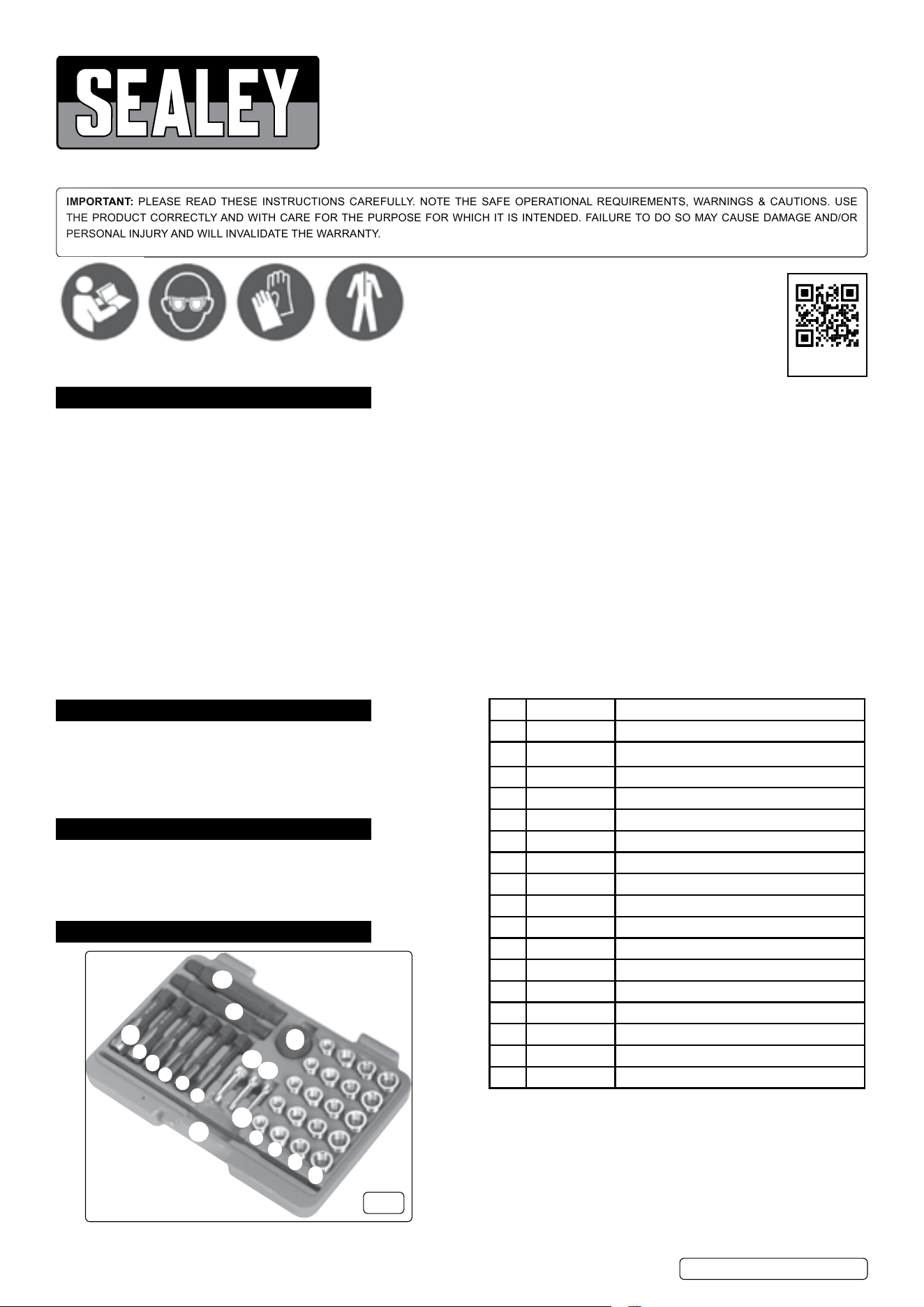
4. CONTENTS
fig.1
14
15
16
17
12
1
2
13
9
10
11
3
4
5
6
7
8
Item Part No: Description:
1 VS311.01 Thread Insert M8 x 1.0
2 VS311.02 Thread Insert M10 x 1.0
3 VS311.03 Thread Insert M10 x 1.25
4 VS311.04 Thread Insert M12 x 1.25
5 VS311.05 Tap M8 x 1.0
6 VS311.06 Tap M10 x 1.0
7 VS311.07 Tap M10 x 1.25
8 VS311.08 Tap M12 x 1.0
9 VS311.09 Tap M12 x 1.25
10 VS311.10 Tap M14 x 1.25
11 VS311.11 Insert Driver M8x1.0 & M10x1.0
12 VS311.12 Insert Driver M10x1.25 & M12x1.25
13 VS311.V2.13 Tap Guide Pin ø8 x 33.5mm
14 VS311.V2.14 Tap Guide Pin ø10 x 33.5mm
15 VS311.V2.15 Tap Guide Pin ø12 x 33.5mm
16 VS311.16 Insert Guide Rod
17 VS311.17 Knurled Head
Wear
protective
clothing
Wear protective
gloves
VS311.V2 Issue 3 04/09/24
Consumable Parts:
VS311.01 - M8 x 1mm (Pack of 5), VS311.02 - M10 x 1mm
(Pack of 5)
VS311.03 - M10 x 1.25mm (Pack of 5)
VS311.04 - M12 x 1.25mm (Pack of 5)
REGISTER YOUR
PURCHASE HERE
5. OPERATION
NOTE: To minimise the possibility of damage to the engine,
it is advisable to remove the cylinder head from the engine
prior to commencing work of this nature.
The tap guide system included with this set will significantly
reduce the ingress of swarf/debris into
the combustion chamber and cylinder.
Always wear eye and hand protection
when cleaning any swarf/debris from the
engine. A full range of personal safety
equipment is available from your Sealey
stockist.
5.1. REPAIRING A DAMAGED THREAD USING A TAP
WARNING! Ensure you have read, understood and apply Section 1 safety instructions.
5.1.1. Determine the size of the thread to be repaired. This can be done by carefully using the insert drivers to compare with the thread of an
undamaged glow plug aperture.
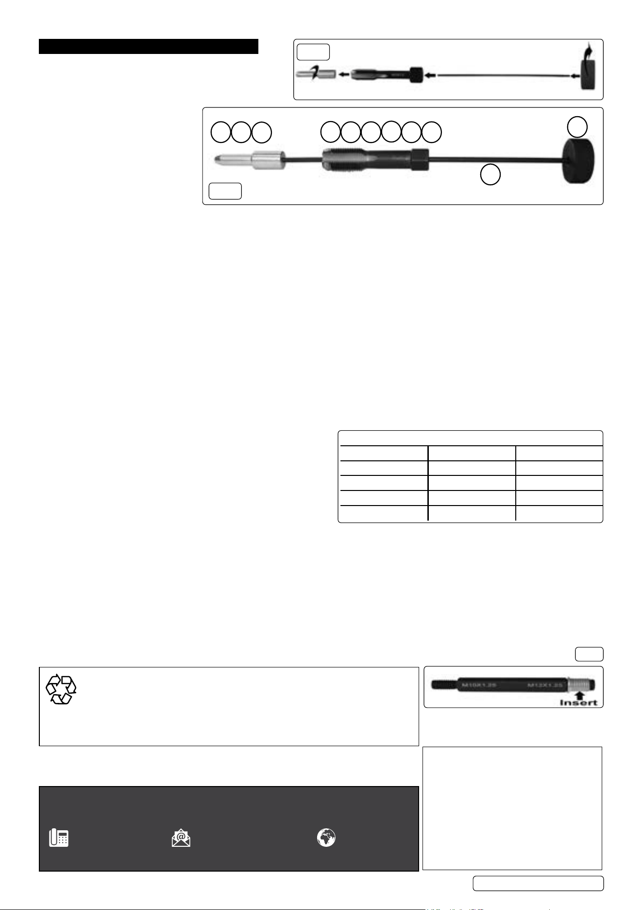
5.1.2. Usingthecorrectsizeoftapandinsertguide,assemblethesetasshowning.2andg.3.
5.1.3. If a ring spanner is to be used, position on the tap before inserting the insert guide pin into the glow plug aperture. Apply a layer of
general purpose grease to the insert guide to help prevent swarf/debris from entering the engine and place into the glow plug aperture.
5.1.4. Hold the knurled head (17) and position the guide rod (16) so that the insert guide pin is squarely positioned in the glow plug aperture.
5.1.5. Using a spanner with adequate downward pressure, carefully run the tap down the damaged thread 1/2 of a turn forward
then1/4ofaturnbacktorepairthedamagedthread.Alwaysuseasuitablecuttinguid.Periodicallyremovethetapandinsert
5.1.6. guide to clean away the swarf/debris. Apply a layer of general purpose grease to the insert guide before re-inserting into the glow
plug aperture. Continue until the full length of the thread has been repaired.
NOTE: It is very important to clean away as much swarf/debris as possible during the thread cutting process to avoid any
ingress into the engine.
5.1.7. Oncethethreadhasbeenrepaired,ensurethatallswarf/debrishasbeencompletelyremovedandcarefullyttheglowplug.
5.1.8. Ensure all tools are removed from the engine bay and stored away. Store in a safe, dry, childproof location.
5.2. REPAIRING A DAMAGED THREAD USING AN INSERT
WARNING! Ensure you have read, understood and apply Section 1 safety instructions.
5.2.1. Determine the size of the thread to be repaired. This can be done by carefully using the insert drives to compare with the
thread of an undamaged glow plug aperture.
5.2.2. Usingthetableabove,assembletheset,asshowning.2and
g.3withthecorrecttapandinsertguidecongurationforthe
size of insert required.
5.2.3. If a ring spanner is to be used, position on the tap before inserting
the insert guide into the glow plug aperture.
5.2.4. Apply a layer of general purpose grease to the insert guide to
help prevent swarf/debris from entering the engine and place
into the glow plug aperture.
5.2.5. Hold the knurled handle and position the guide rod so that the insert guide is squarely positioned in the glow plug aperture.
5.2.6. Using a spanner with adequate downward pressure, carefully run the tap down through glow plug aperture 1/2 of a turn
forwardthen1/4ofaturnbacktocutathreadfortheinsert.Alwaysuseasuitablecuttinguid.Periodicallyremovethetapand
insert guide to clean away the swarf and debris. Apply a layer of general purpose grease to the insert guide to assist with the removal
ofswarf/debrisbeforere-insertingintotheglowplugaperture.Continueuntilthelengthofthreadcutissucienttoaccommodatethe
insert. Ensure that all swarf/debris is completely removed from the glow plug aperture.
5.2.7. Screwtheinsertontotherelevantinsertdrive(g.4).
5.2.8. Apply a suitable thread locking solution to the exterior thread of the insert. Screw the insert into the prepared glow plug
apertureuntiltheangeatthetopoftheinsertlocatesatthetopoftheaperturethreadandtightenusingasuitablespanner.
5.2.9. Remove the insert driver, taking care not to dislodge the insert.
5.2.10. Allowthethreadlockingsolutiontocompletelycurebeforettingtheglowplug.
5.2.11. Ensure all tools are removed from the engine bay and stored away. Store in a safe, dry, childproof location.
fig.2
fig.3
13
14
15
16
17
10
5 6
7
8
9
Insert/Tap/Guide Congurations (Refer to g.1 & g.2)
Insert Size: Tap Size: Guide Size:
M8x1.0 (1) M10x1.0 (6) M8 (13)
M10x1.0 (2) M12x1.0 (8) M10 (14)
M10x1.25 (3) M12x1.25 (9) M10 (14)
M12x1.25 (4) M14x1.25 (10) M12 (15)
fig.4
Original Language Version
© Jack Sealey Limited
ENVIRONMENT PROTECTION
Recycle unwanted materials instead of disposing of them as waste. All tools, accessories
and packaging should be sorted, taken to a recycling centre and disposed of in a manner
which is compatible with the environment. When the product becomes completely
unserviceable and requires disposal, drain any fluids (if applicable) into approved
containers and dispose of the product and fluids according to local regulations.
Note: It is our policy to continually improve
products and as such we reserve the right
to alter data, specifications and component
parts without prior notice. Please note that
other versions of this product are available.
If you require documentation for alternative
versions, please email or call our technical
team on technical@sealey.co.uk or 01284
757505.
Sealey Group, Kempson Way, Suffolk Business Park, Bury St
Edmunds, Suffolk. IP32 7AR
01284 757500 sales@sealey.co.uk www.sealey.
co.uk
Important: No Liability is accepted for incorrect use of this product.
Warranty: Guarantee is 12 months from purchase date, proof of which is required for any claim.
VS311.V2 Issue 3 04/09/24
