
8 & 10MM GLOW PLUG HEATER ELEMENT
REMOVAL SET
MODEL NO: VS315
Thank you for purchasing a Sealey product. Manufactured to a high standard, this product will, if used according to these
instructions, and properly maintained, give you years of trouble free performance.
IMPORTANT: PLEASE READ THESE INSTRUCTIONS CAREFULLY. NOTE THE SAFE OPERATIONAL REQUIREMENTS, WARNINGS & CAUTIONS. USE
THE PRODUCT CORRECTLY AND WITH CARE FOR THE PURPOSE FOR WHICH IT IS INTENDED. FAILURE TO DO SO MAY CAUSE DAMAGE AND/OR
PERSONAL INJURY AND WILL INVALIDATE THE WARRANTY. KEEP THESE INSTRUCTIONS SAFE FOR FUTURE USE.
1. SAFETY
WARNING! Ensure Health and Safety, local authority and general workshop practice regulations are adhered to when using tools.
8 DO NOT use tools if damaged.
8 DO NOT attempt to start engine or move vehicle whilst tools are fitted and work is in progress.
9 Maintain tools in good and clean condition for best and safest performance.
9 Wear approved eye protection. A full range of personal safety equipment is available from your Sealey stockist.
9 Wear suitable clothing to avoid snagging. DO NOT wear jewellery and tie back long hair.
9 Ensure any disconnected fuel pipes are plugged to avoid spillage.
9 Account for all tools and parts being used, DO NOT leave them in or near the engine. Return all parts to the case and store this in a
safe, dry, childproof location.
IMPORTANT: These instructions are provided as a guide only. Always refer to the vehicle manufacturer’s service instructions, or a
proprietary manual, to establish the current procedure and data.
WARNING! The warnings referred to in this guide cannot cover all possible conditions and situations that may occur. It must be
understood that common sense and caution are factors which cannot be built into this product, but must be applied by the operator.
2. INTRODUCTION
For removing the heater element that can break off during glow plug removal. Saves time not having to remove the cylinder head. Works by
drilling/tapping a thread into the broken element so the supplied glow plug adaptors can be used to extract. Supplied with seven drilling/tapping
guides and ve glow plug extraction adaptors with either a M8 or M10 thread.
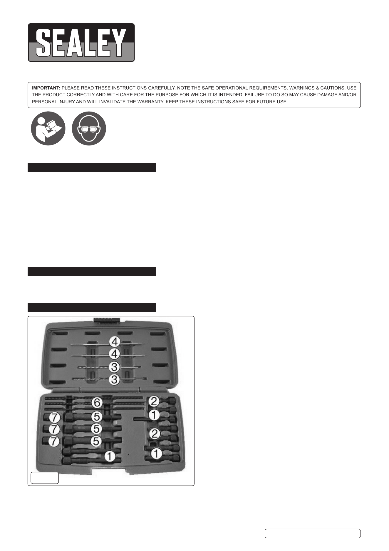
3. CONTENTS
KEY:
1 . . . . . . . Drilling Guides: M8 x 1, M10 x 1, M10 x 1.25mm
2 . . . . . . . . . . . . . . Tapping Guides: M8 x 1, M10 x 1.25mm
3 . . . . . . . . . . . . . . . . . . . . . . . . . . . . . . Drills: Ø 2.5, 3.3mm
4 . . . . . . . . . . . . . . . . . . . . . . . Taps: M3 x 0.5, M4 x 0.7mm
5 . . . Extraction Adaptors: M8 x 1, M10 x 1, M10 x 1.25mm
6 . . . . . . . . . . . . . . Threaded Rods: M3 x 0.5, M4 x 0.7mm
7 . . . . . . . . . . . . . . . . . . . . . . . . . . . . . . . . . . .Extractor Nuts
g.1
VS315 Issue 2 (4) 21/05/20
Original Language Version
© Jack Sealey Limited
Refer to
instructions
Wear eye
protection
4. INSTRUCTIONS
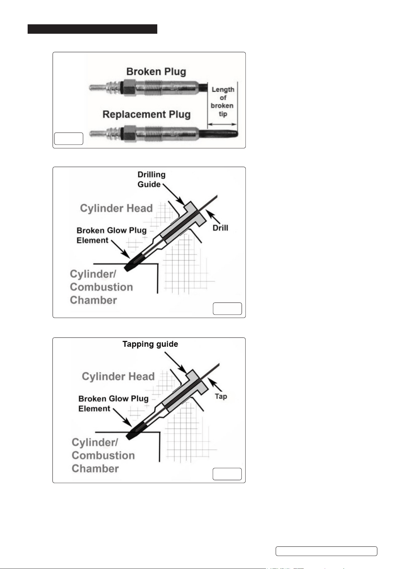
4.1. With reference to the replacement glow plug, nd the matching drilling guide and screw into the glow plug port.
4.2. Determine the length of the broken portion as in g.2.
4.3. Place the appropriate drill (2.5mm for M8, 3.3mm for M10) in a drill and, using the drill guide (g 1.1), drill into the broken glow plug
element to a depth of approximately 10mm if the broken stub is long enough (g 3).
4.4. Select the appropriate tap and cut a thread into the broken glow plug element ensuring the tap is turned back frequently to clear
swarf away from the cutter. (g.4). Ensure a good quality cutting uid such as Sealey SCSCF400 is used when cutting the thread.
g.2
g.3
VS315 Issue 2 (4) 21/05/20
Original Language Version
© Jack Sealey Limited
g.4
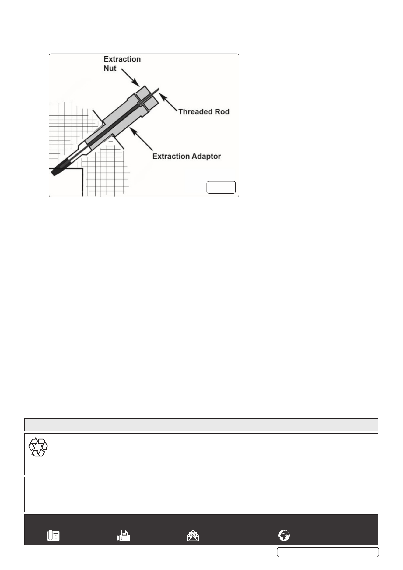
4.5. Once a thread has been formed into the broken glow plug element, remove the tap and tap guide.
4.6. Screw in the appropriate extraction adaptor. Select the appropriate threaded rod and screw into the broken glow plug element.
4.7. Run the correct extractor nut down the threaded rod until it makes contact with the extraction adaptor. Turn the extractor nut gently
with a spanner until the broken portion comes free. (g.5).
4.8. Unscrew the extraction adaptor carefully and remove it, along with the threaded rod and glow plug element. As the glow plug
element reaches the top of the port, brush or blow away any swarf to reduce the risk of debris entering the aperture.
4.9. Examine the glow plug element and the aperture to ensure that no debris is in the glow plug port before tting the replacement glow
plug.
g.5
Sealey Group, Kempson Way, Suffolk Business Park, Bury St Edmunds, Suffolk. IP32 7AR
01284 757500 01284 703534 sales@sealey.co.uk www.sealey.co.uk
ENVIRONMENT PROTECTION
Recycle unwanted materials instead of disposing of them as waste. All tools, accessories and packaging should be sorted, taken to
a recycling centre and disposed of in a manner which is compatible with the environment. When the product becomes completely
unserviceable and requires disposal, drain any fluids (if applicable) into approved containers and dispose of the product and fluids
according to local regulations.
Note: It is our policy to continually improve products and as such we reserve the right to alter data, specifications and component parts without prior
notice.
Important: No Liability is accepted for incorrect use of this product.
Warranty: Guarantee is 12 months from purchase date, proof of which is required for any claim.
VS315 Issue 2 (4) 21/05/20
Original Language Version
© Jack Sealey Limited
Parts support is available for this product. Please email sales@sealey.co.uk or telephone 01284 757500