
8 & 10MM DAMAGED GLOW PLUG REMOVAL SET
MODEL NO:SX0408.V2
Thank you for purchasing a Sealey product. Manufactured to a high standard, this product will, if used according to these instructions,
and properly maintained, give you years of trouble free performance.
IMPORTANT: PLEASE READ THESE INSTRUCTIONS CAREFULLY. NOTE THE SAFE OPERATIONAL REQUIREMENTS, WARNINGS & CAUTIONS. USE
THE PRODUCT CORRECTLY AND WITH CARE FOR THE PURPOSE FOR WHICH IT IS INTENDED. FAILURE TO DO SO MAY CAUSE DAMAGE AND/OR
PERSONAL INJURY AND WILL INVALIDATE THE WARRANTY. KEEP THESE INSTRUCTIONS SAFE FOR FUTURE USE.
Refer to
instruction
manual
Original Language Version
© Jack Sealey Limited
Wear protective
gloves
1. SAFETY
WARNING! Ensure Health and Safety, local authority and general workshop practice regulations are adhered to when using tools.
8 DO NOT use tools if damaged.
9 Maintain tools in good and clean condition for best and safest performance.
9 Wear approved eye protection. A full range of personal safety equipment is available from your Sealey dealer.
9 Wear suitable clothing to avoid snagging. DO NOT wear jewellery and tie back long hair.
8 DO NOT attempt to start engine or move vehicle whilst tools are fitted and work is in progress.
9 Ensure any disconnected fuel pipes are plugged to avoid spillage.
9 Account for all tools and parts being used, DO NOT leave them in or near the engine. Return all parts to the case and store this in a
safe, dry, childproof location.
WARNING! These instructions are provided as a guide only. Always refer to the vehicle manufacturer’s service instructions, or a
proprietary manual, to establish the current procedure and data.
WARNING! The warnings referred to in this guide cannot cover all possible conditions and situations that may occur. It must be
understood that common sense and caution are factors which cannot be built into this product, but must be applied by the operator.
2. INTRODUCTION
Designed to remove damaged/broken glow plugs from cylinder heads. Suitable for glow plugs with an M8 x 1mm and M10 x 1mm
thread. Set includes all required adaptors for drilling, centring and pulling for the safe removal of glow plug. Supplied in storage case.
3. SPECIFICATION
Model Number:.............................................................. ..SX0408.V2
Contents: Taps; 1/4NF28, M8 x 1mm, M10 x 1mm, Glow Plugs; M8 x 1mm, M10 x 1mm
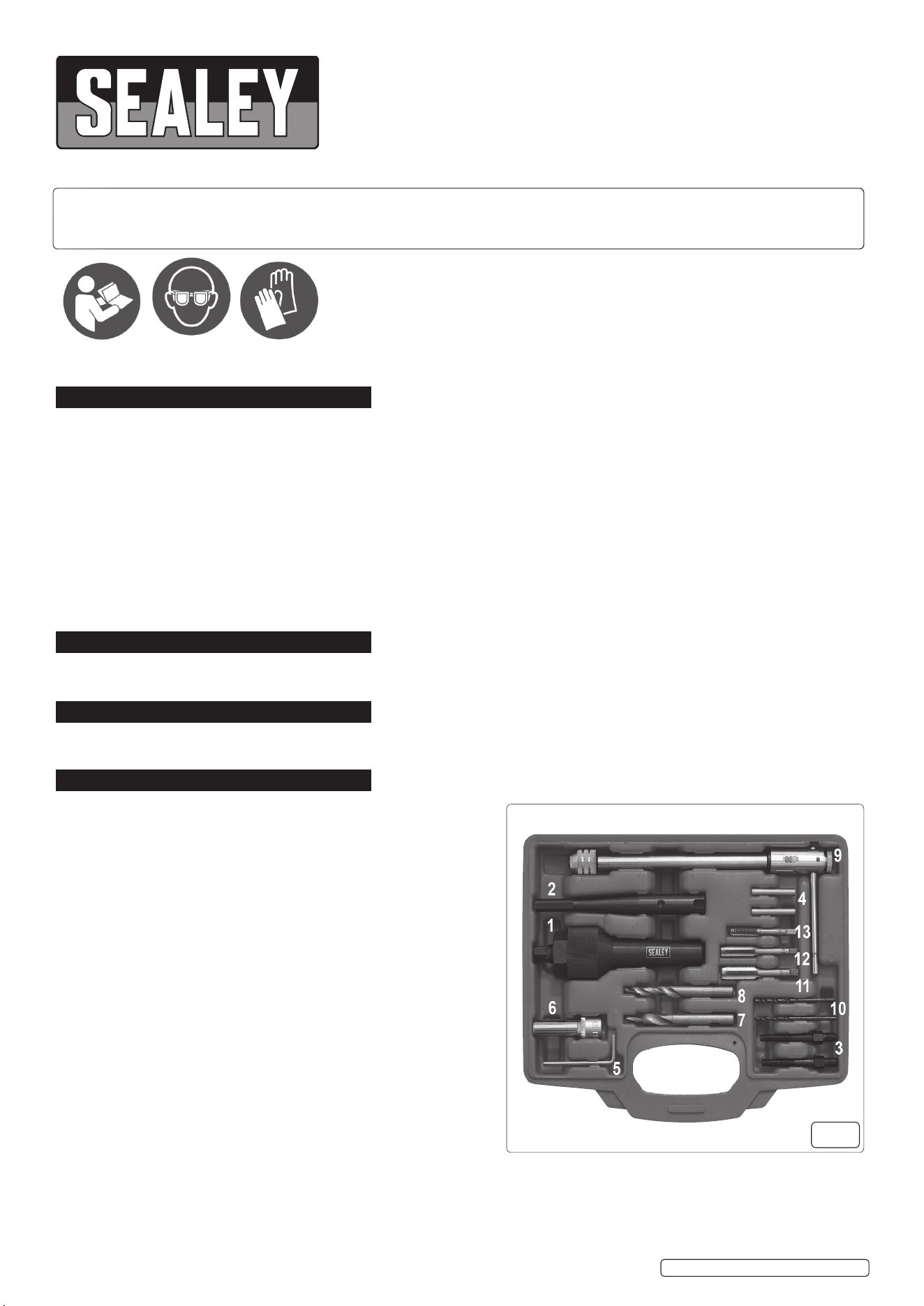
4. CONTENTS
Wear eye
protection
SX0408.V2 Issue: 2 (H,F) 27/07/23
Key to Fig 1:
Number Part No. Description
1................ SX0408.V2-01............................................ Puller Housing
2................ SX0408.V2-02................................... Drill Holding Adaptor
3................ SX0408.V2-03............ Puller Adaptor Mandrels (2 pcs/set)
4................ SX0408.V2-04........Pilot Drill Centring Sleeves (2pcs/set)
5................ SX0408.V2-05........................................... Hex Key (3mm)
6................ SX0408.V2-06........................................ Star Socket (E10)
7................ SX0408.V2-07................................ Drill Bit (7mm /5.5mm)
8................ SX0408.V2-08................................ Drill Bit (9mm/5.5mm)
9................ SX0408.V2-09............................................. Ratchet T- Bar
10............... SX0408.V2-10................................... Pilot Drills (2pcs/set)
11................ SX0408.V2-11........................................... Tap (M10 x 1.0)
12............... SX0408.V2-12............................................. Tap (M8 x 1.0)
13............... SX0408.V2-13.......................................... Tap (¼”-28UNF)
g.1
5. OPERATION
Numberswithinthebracketsrefertoitemsing.1
5.1. NOTE: To minimise the possibility of damage to the engine, it is advisable to remove the cylinder head from the engine to work on it.
Alternatively, remove the relevant injector and connect an air line via an appropriate adaptor to the aperture to ensure dirt and swarf do
not enter the combustion chamber as the procedure is carried out. Wear eye protection.
5.2. PushtStarSocket(6)ontothetopoftheglowplug;itmayneedtobetappedonlightly.Then,usinga⅜”ratchet,remove/breakoff
the top part of the glow plug.
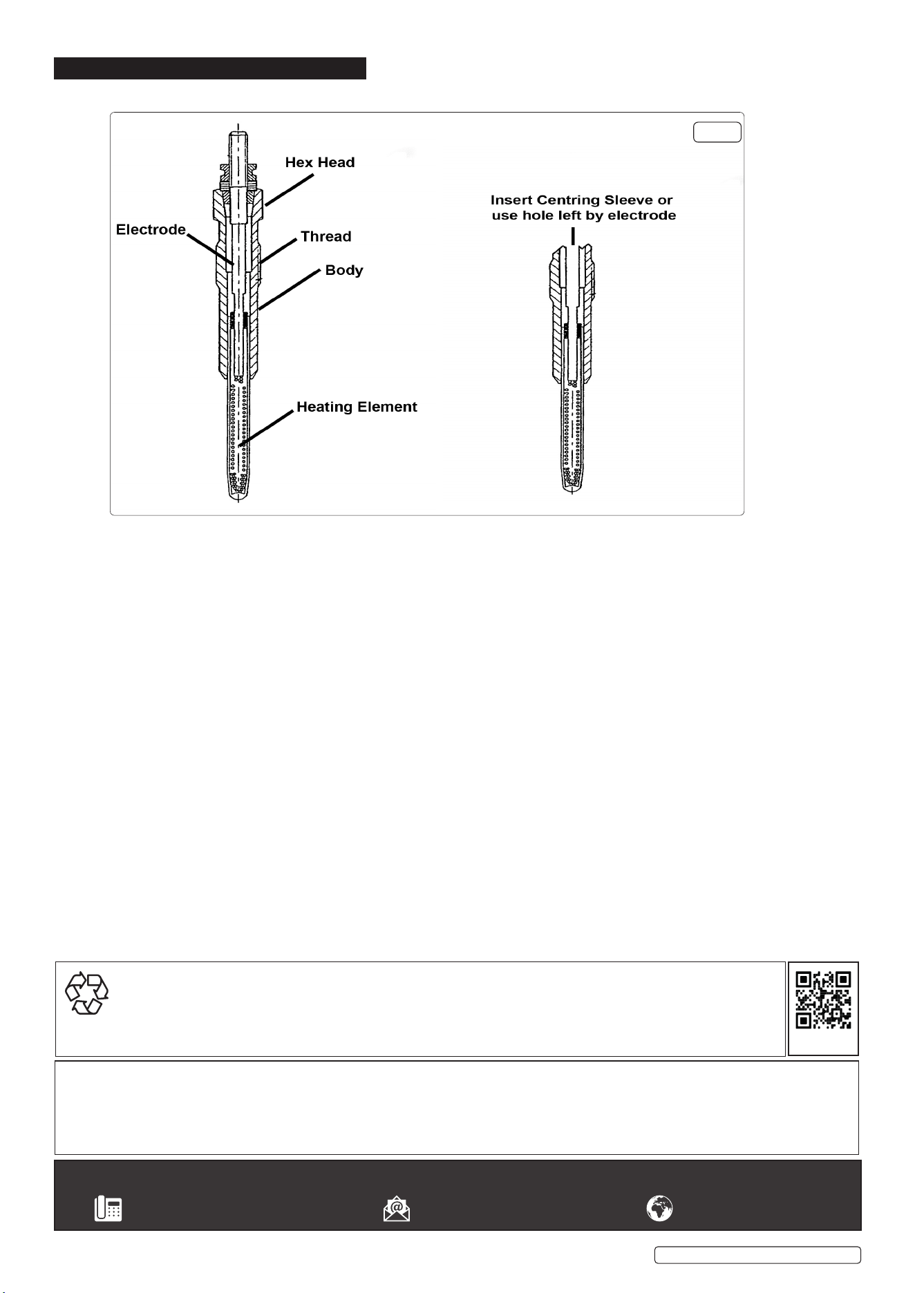
(Seeg.2)InsertCentringSleeve(4)intotherecessinthetopoftheglowplug.FitPilotDrill(10)toanelectricdrillandinsertpilot
drill into centering sleeve, drill a pilot hole in the centre of the glow plug remains. Ensure that pilot drilling is at least 15mm deep. Clean
away the swarf using an air line. Note: If the electrode can be withdrawn in one piece, the aperture created may be used as a pilot.
If this is the case, proceed to 5.4.
5.3. Fit either 7mm (7) or 9mm (8) Drill Bit into the Drill Holding Adaptor (2) and lock in place with the grub screw, using the hex key (5).
Makesurethatthegrubscrewbearsontheat,machinedintotheshankofthedrillbit.Carefullydrilloutthecentreoftheglowplug
and threaded portion of glow plug body. Take care not to damage the female threads in the cylinder head.
Clean out the swarf using an air line.
5.4. Fit the ¼” tap provided into the ratchet T-bar. Cut a thread with this in the remains of the glow plug body, cutting at least 15mm of
thread.
5.5. Screw a Puller Adaptor Mandrel (3) into the thread that has just been cut into the glow plug. Remove the nut from the force screw in
the Puller Housing (1) and thread the force screw onto the mandrel. Slide the outer sleeve of the puller housing over the force screw.
5.6. Re-tthenuttotheforcescrewwiththecollarfacingtheoutersleeve.Holdtheheadoftheforcescrewwitha12mmwrenchorsocket
and wind the nut down using a 30mm wrench.This will draw the remaining lower part of the glow plug free from the cylinder head.
5.7. Fit either M8 (12) or M10 (11) Tap into Ratchet T-Bar (9). Run the tap down to clean/restore the threads in the cylinder head. An
application of grease to the tap will both lubricate and help contain the swarf.
5.8. Clean thoroughly the thread and surrounding area and make sure that the combustion chamber (if head is in-situ) is free from debris
beforettingareplacementglowplug.
5.9. Ensure all tools are removed from the engine bay and returned to the tool tray, and store this in a safe, dry, childproof location.
g.2
© Jack Sealey Limited
Original Language Version
Sealey Group, Kempson Way, Suffolk Business Park, Bury St Edmunds, Suffolk. IP32 7AR
01284 757500 sales@sealey.co.uk www.sealey.co.uk
SX0408.V2 Issue: 2 (H,F) 27/07/23
Note: It is our policy to continually improve products and as such we reserve the right to alter data, specifications and component parts without prior
notice. Please note that other versions of this product are available. If you require documentation for alternative versions, please email or call
our technical team on technical@sealey.co.uk or 01284 757505.
Important: No Liability is accepted for incorrect use of this product.
Warranty: Guarantee is 12 months from purchase date, proof of which is required for any claim.
ENVIRONMENT PROTECTION
Recycle unwanted materials instead of disposing of them as waste. All tools, accessories and packaging should be sorted,
taken to a recycling centre and disposed of in a manner which is compatible with the environment. When the product
becomes completely unserviceable and requires disposal, drain any fluids (if applicable) into approved containers and
dispose of the product and fluids according to local regulations.
REGISTER YOUR
PURCHASE HERE
Glow plug with electrode
withdrawn
Glow plug
construction