72MM FRONT WHEEL BEARING GEN2
REMOVAL/INSTALLATION KIT
MODEL NO: VS7029.V3
Thank you for purchasing a Sealey product. Manufactured to a high standard, this product will, if used according to these instructions,
and properly maintained, give you years of trouble free performance.
IMPORTANT: PLEASE READ THESE INSTRUCTIONS CAREFULLY. NOTE THE SAFE OPERATIONAL REQUIREMENTS, WARNINGS & CAUTIONS. USE
THE PRODUCT CORRECTLY AND WITH CARE FOR THE PURPOSE FOR WHICH IT IS INTENDED. FAILURE TO DO SO MAY CAUSE DAMAGE AND/OR
PERSONAL INJURY AND WILL INVALIDATE THE WARRANTY. KEEP THESE INSTRUCTIONS SAFE FOR FUTURE USE.
1. SAFETY
WARNING! Ensure Health & Safety, local authority, and general workshop practice regulations are adhered to when using this tool.
WARNING! Familiarise yourself with the specic applications and limitations of the kit, as well as any potential hazards.
9 Ensure that the kit is correct for the task.
9 Wear the appropriate personal protective equipment for the task. A full range is available from your Sealey stockist.
8 DO NOT use a workshop press to t GEN2 wheel bearings.
8 DO NOT t a wheel bearing with a damaged retaining ring.
8 DO NOT use the kit for any purpose other than that for which it is designed.
8 DO NOT use air tools with this kit to remove/install bearings.
9 Always keep force screw well lubricated.
9 Ensure that the vehicle is properly supported with axle stands before working under the vehicle.
9 Ensure there is adequate lighting prior to using the kit. A range of inspection lamps are available from your Sealey stockist.
9 Keep children and unauthorised persons away from the working area.
8 DO NOT use the kit if any parts are damaged or missing, as this may cause failure and/or personal injury.
8 DO NOT use the kit when you are tired, or under the inuence of alcohol, drugs or intoxicating medication.
9 After use, store in a safe, dry childproof area.
▲ IMPORTANT: Always refer to the vehicle manufacturer’s service instructions, or a proprietary manual, to establish the current
procedure and data.
WARNING: The warnings, cautions and instructions in this manual cannot cover all possible conditions and situations that may occur.
It must be understood that common sense and caution are factors which cannot be built into this product, but must be applied by the
operator.
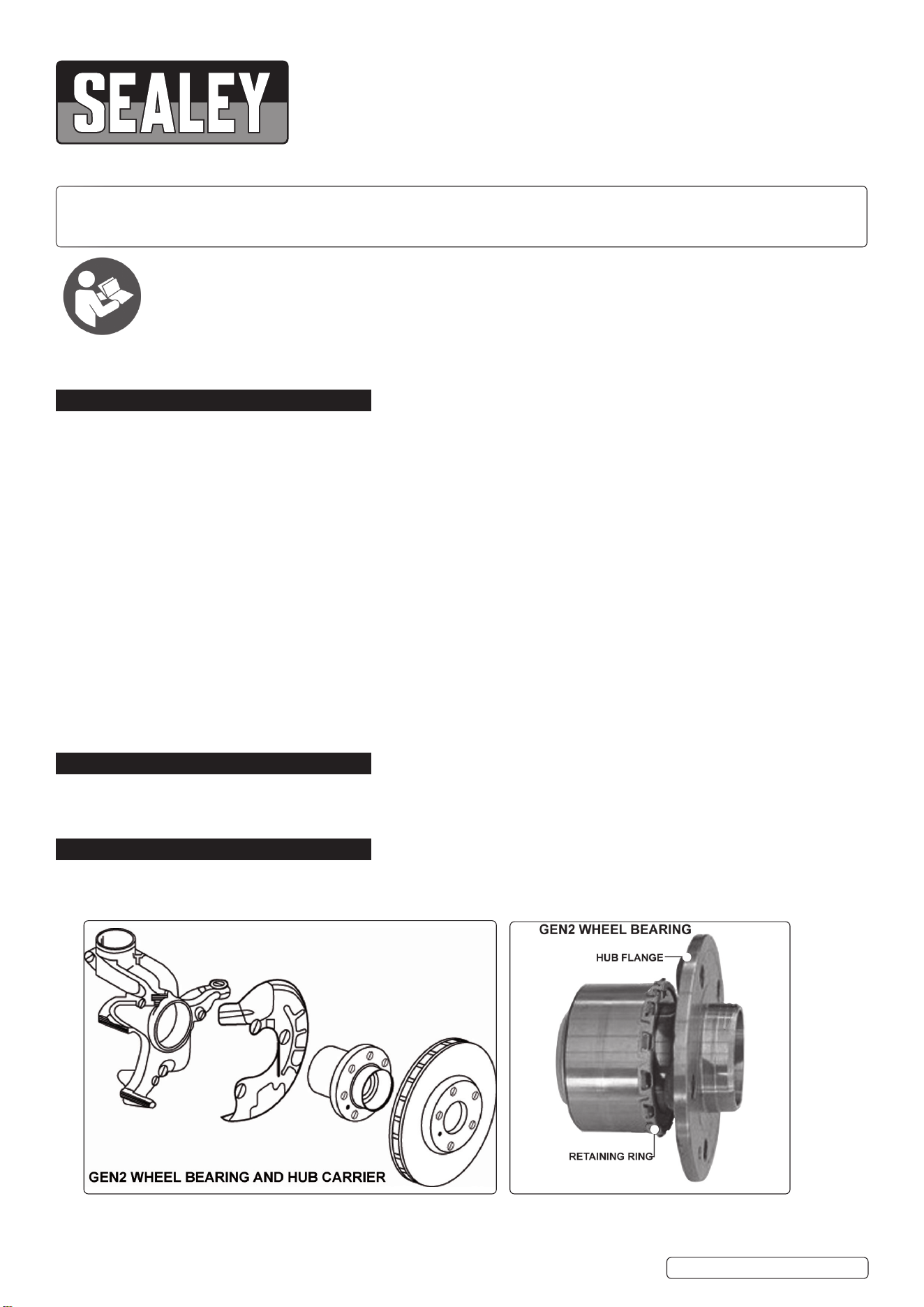
2. INTRODUCTION
Designed for the second generation of wheel bearing found on modern vehicles. These bearings are lightweight with an integral mounting
ange. They are also pre-loaded with a retaining ring that secures the bearing into the housing. Suitable to be used in situ when replacing the
front wheel bearings. Supplied in storage case.
3. SPECIFICATION
Model no: ............................................................. VS7029.V3
Bearing size: ................................................................ 72mm
Original Language Version
© Jack Sealey Limited
Refer to
instruction
manual
VS7029.V3 Issue:1 07/08/23
Original Language Version
© Jack Sealey Limited
Model No VS7029.V3
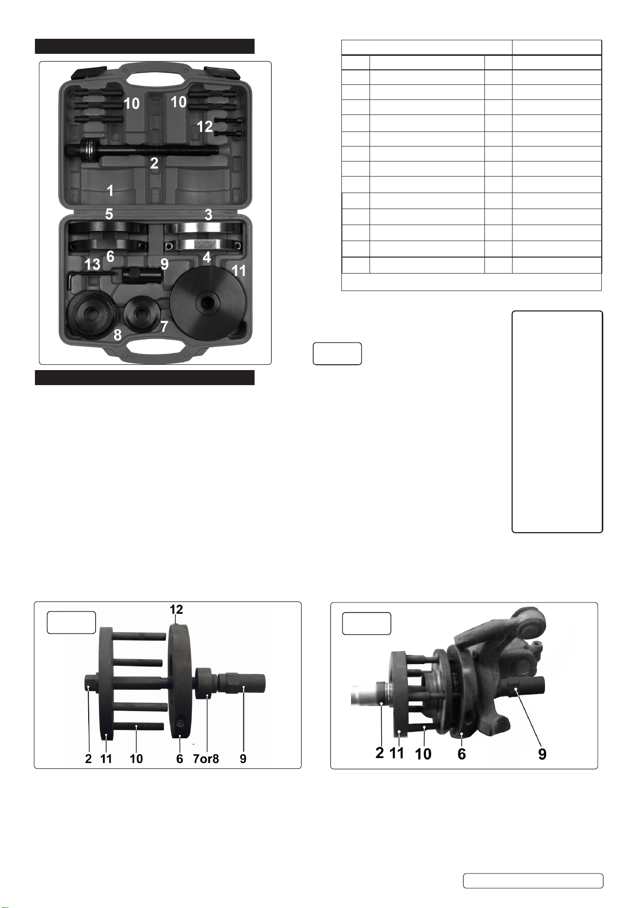
Item Description Qty Part Numbers
1 Case 1 VS7029-V3-01
2 Force screw VS7029-V3-02
3 Hub clamp stud end silver 1 VS7029-V3-03
4 Hub clamp silver 1 VS7029-V3-04
5 Hub clamp stud end black 1 VS7029-V3-05
6 Hub clamp black 1 VS7029-V3-06
7 Bearing plate small 1 VS7029-V3-07
8 Bearing plate large 1 VS7029-V3-08
9 Sleeved nut 1 VS7029-V3-09
10 Hub guide pin 1 VS7029-V3-10
11 Thrust plate 1 VS7029-V3-11
12 Socket cap bolt 1 VS7029-V3-12
13 Hex key 1 VS7029-V3-13
Applications
Audi
A1 (2010 - on)
A2 (00-05)
Seat
Cordoba (03-09)
Ibiza (02-12)
Skoda
Fabia (00-12)
Roomster (06-12)
VW
Fox (05-10)
Polo (02-12)
fig.1
4. CONTENTS
5. OPERATION
5.1. BEARING REMOVAL (g.2 & g.3)
5.1.1. Prepare the vehicle for the wheel bearing to be removed.
Note: When GEN2 wheel bearings are removed, the retaining ring will sustain damage.
DO NOT re-t a bearing once it has been removed.
5.1.2. Fit the black hub clamp (5,6) behind the hub ange with the recessed side facing the hub carrier.
Secure the hub clamp (5,6) with the hub clamp screws (12).
5.1.3. Fit the hub guide pins (10) into the thrust plate (11) so that the hub guide pins (10) align with the holes
in the hub ange. Place the hub guide pins (10) though the holes in the hub ange so that they sit against
the hub clamp (5,6) (g.3).
5.1.4. Lubricate the force screw (2).
5.1.5. Fit the force screw (2) through the thrust plate (11) and through the bearing and hub carrier.
5.1.6. Place the black bearing plate (7,8) over the force screw (2) so that it sits on the outer race of the
bearing.
5.1.7. Screw the sleeved nut (9) over the force screw (2) so that it sits against the bearing plate (7,8).
5.1.8. Use a socket on the force screw (2) and a spanner on the sleeved nut (9) (g.3). Draw the bearing from the hub carrier.
fig.2
fig.3
VS7029.V3 Issue:1 07/08/23
Sealey Group, Kempson Way, Suffolk Business Park, Bury St Edmunds, Suffolk. IP32 7AR
01284 757500 sales@sealey.co.uk www.sealey.co.uk
ENVIRONMENT PROTECTION
Recycle unwanted materials instead of disposing of them as waste. All tools, accessories and packaging should be sorted,
taken to a recycling centre and disposed of in a manner which is compatible with the environment. When the product
becomes completely unserviceable and requires disposal, drain any fluids (if applicable) into approved containers and
dispose of the product and fluids according to local regulations.
Note: It is our policy to continually improve products and as such we reserve the right to alter data, specifications and component parts without prior
notice. Please note that other versions of this product are available. If you require documentation for alternative versions, please email or call
our technical team on technical@sealey.co.uk or 01284 757505.
Important: No Liability is accepted for incorrect use of this product.
Warranty: Guarantee is 12 months from purchase date, proof of which is required for any claim.
Original Language Version
© Jack Sealey Limited
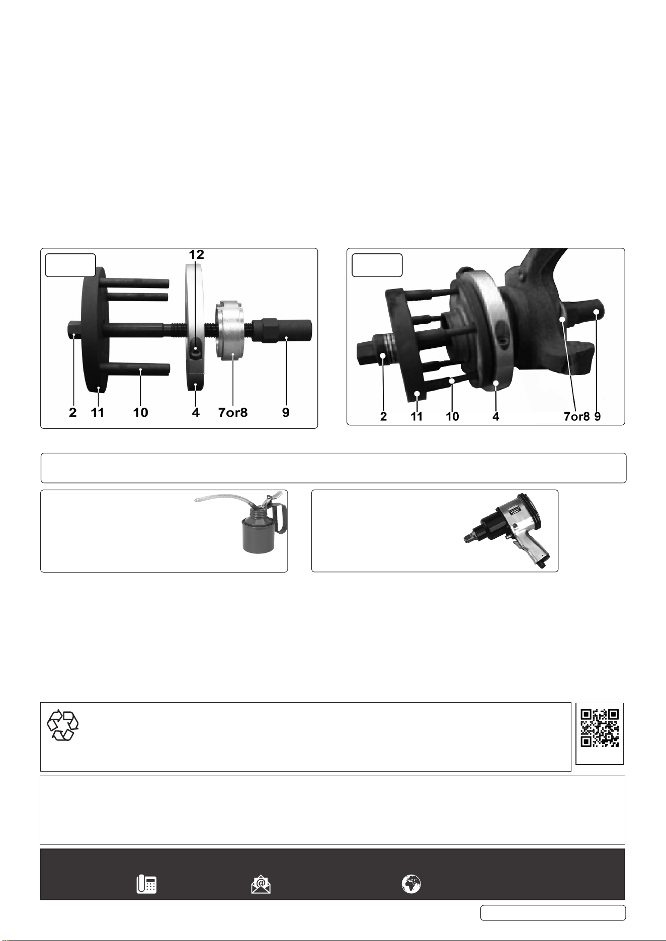
5.2. BEARING INSTALLATION (g.4 & g.5)
WARNING! DO NOT t a bearing with a damaged retaining ring.
Note: The bearing must only be subjected to force on the outer bearing race behind the retaining ring during installation. Using a
workshop press on the hub ange to insert the bearing will cause premature failure or destroy the bearing during installation.
5.2.1. The silver hub clamp (3,4) sits in the space between the rear of the hub ange and the retaining ring (g.5). Secure hub clamp (3,4)
with the hub clamp screws (12).
5.2.2. Fit the hub guide pins (10) into the thrust plate (11) so that the hub guide pins (10) align with the holes in the hub ange. Place the hub
guide pins (10) though the holes in the hub ange so that they sit against the hub clamp (3,4).
5.2.3. Lubricate the force screw (2).
5.2.4. Oer the bearing and assembled kit to the hub carrier. Ensure that the bearing is sitting square to the hub carrier before commencing
installation.
5.2.5. Fit the force screw (2) through the thrust plate (11) and through the bearing and hub carrier.
5.2.6. Place the bearing plate (7,8) over the force screw (2) so that it sits on the outer edge at the rear of the hub carrier.
5.2.7. Screw the sleeved nut (9) over the force screw (2) so that it sits against the bearing plate (7,8).
5.2.8. Use a socket on the force screw (2) and a spanner on the sleeved nut (9). Draw the bearing into the hub carrier.
5.2.9. When the bearing is correctly installed, the retaining ring will clip into the retaining groove.
DO NOT USE AIR TOOLS
The force screw maximum torque is 150Nm. Exceeding this will shorten the life of the force screw. The force screw is considered
to be a consumable item and is NOT covered under warranty.
ALWAYS KEEP THE FORCE SCREW
WELL LUBRICATED. A COPPER BASED
LUBRICANT IS RECOMMENDED.
X
VS7029.V3 Issue:1 07/08/23
fig.4 fig.5
REGISTER YOUR
PURCHASE HERE