Loading ...
Loading ...
Loading ...
41
2. LED Lights and Audible Alarm Safeties
The "POWER OK" LED indicates proper control voltage and will remain on unless a
control voltage problem occurs. For further details, see "II.A. Sequence of Operation Flow
Chart."
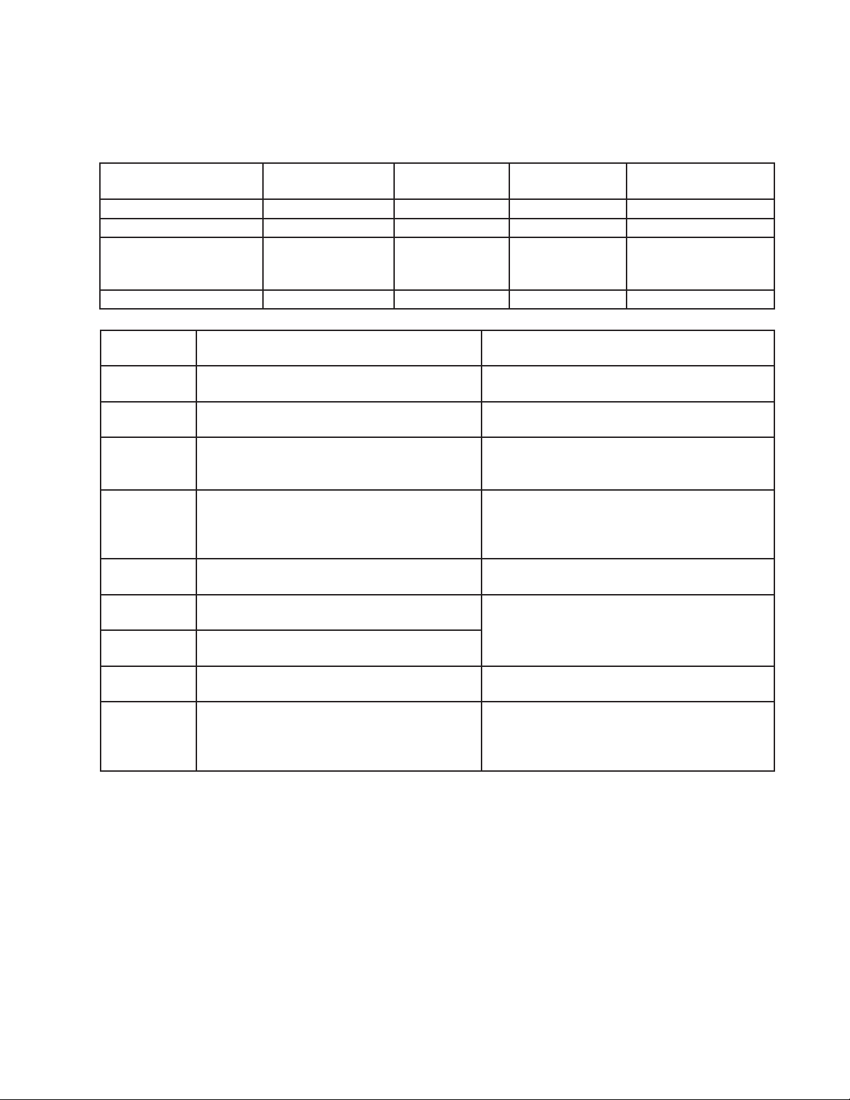
Sequence Step LED
Energized
Components Min. Max.
Fill Cycle WTRIN WV - -
Ice Purge Cycle GM GM, FM/FMR 5 min. 5 min.
Freeze Cycle (with rell) GM, WTRIN* (rell),
COMP
GM, Comp,
FM/FMR, LLV,
SLV, WV* (rell)
- *On until UFS closes.
Alarm sounds after
90 sec.
Drain Cycle FLUSH (Drain) DV 2 sec. 10 min.
The built-in alarm safeties shut down the unit.
No. of Beeps
(every 5 sec.)
Type of Alarm Reset Options
1 Low Water Safety
UFS open > 90 sec. after WV energized.
Automatic reset once water supply is restored
and UFS closes.
2 Control Switch
In "DRAIN" position longer than 15 min..
Automatic reset once the control switch is
moved to the "ICE" position.
3 High-Pressure Switch
First and sec. activation in 1 hour.
Automatic reset once pressure drops below the
high pressure threshold and the high pressure
switch closes.
4 High-Pressure Switch
Third activation in 1 hour.
Call for service. To avoid possible catastrophic
failure, it is recommended to leave the
icemaker off until this alarm is resolved.
Manual reset. Turn power off and on again.
5 Freeze Timer
WV off > 30 min. since last WV activation.
Manual reset. Turn power off and on again.
6 Low Voltage
(92VAC±5% or less)
"POWER OK" LED turns off if voltage
protection operates.
The control voltage safeties automatically reset
when voltage is corrected.
7 High Voltage
(147VAC±5% or more)
8 Gear Motor
CCR contacts fail to close.
Manual reset. Turn power off and on again.
9 BC1 (infrared sensor) fails (CB S1 dip switch
7 on)
BC2 (mechanical backup) actuator paddle
engaged.
Manual reset. Turn power off and on again.
Legend: BC1–bin control (infrared sensor); BC2–bin control 2 (mechanical backup);
CB–control board; CCR–compressor control relay; Comp–compressor;
DV–drain valve; FM–fan motor; FMR–fan motor-remote; GM–gear motor;
LLV -liquid line valve (MLH model); SLV –suction line valve (MLH model);
UFS–upper oat switch; WV–inlet water valve
Loading ...
Loading ...
Loading ...