Models
H and J Series
Modular Flaker with
F-A and F-C Control Boards
Service Manual
Number: 73204
Issued: 7-23-2014
Revised: 6-8-2018
hoshizakiamerica.com
2
WARNING
Only qualied service technicians should install and service the appliance. To
obtain the name and phone number of your local Hoshizaki Certied Service
Representative, visit www.hoshizaki.com. No service should be undertaken until
the technician has thoroughly read this Service Manual. Failure to service and
maintain the appliance in accordance with this manual will adversely affect safety,
performance, component life, and warranty coverage and may result in costly water
damage. Proper installation is the responsibility of the installer. Product failure or
property damage due to improper installation is not covered under warranty.
Hoshizaki provides this manual primarily to assist qualied service technicians in the
service of the appliance.
Should the reader have any questions or concerns which have not been satisfactorily
addressed, please call, send an e-mail message, or write to the Hoshizaki Technical
Support Department for assistance.
Phone: 1-800-233-1940; (770) 487-2331
Fax: 1-800-843-1056; (770) 487-3360
E-mail: techsuppor[email protected]
618 Highway 74 South
Peachtree City, GA 30269
Attn: Hoshizaki Technical Support Department
Web Site: www.hoshizaki.com
NOTE: To expedite assistance, all correspondence/communication MUST include the
following information:
• Model Number
• Serial Number
• Complete and detailed explanation of the problem.

3
CONTENTS
Important Safety Information ................................................................................................. 6
I. Construction and Water/Refrigeration Circuit Diagram ....................................................... 8
A. Construction .................................................................................................................. 8
1. Air-Cooled Models .................................................................................................... 8
2. Water-Cooled Models ............................................................................................. 9
3. Remote Air-Cooled Models .................................................................................... 10
4. Low-Side, Parallel Rack System Models ................................................................11
B. Icemaking Unit ............................................................................................................ 12
C. Water/Refrigeration Circuit Diagram ............................................................................ 13
1. Air-Cooled Models .................................................................................................. 13
2. Water-Cooled Models ............................................................................................ 14
3. Remote Air-Cooled Models .................................................................................... 15
4. Low-Side, Parallel Rack System Models ............................................................... 16
II. Sequence of Operation and Service Diagnosis ............................................................... 17
A. Sequence of Operation Flow Chart ............................................................................. 17
1. Icemaking and Drain Cycle .................................................................................... 17
2. Shutdown .............................................................................................................. 18
B. Service Diagnosis ....................................................................................................... 19
C. Control Board Check ................................................................................................... 25
D. Bin Control Check ....................................................................................................... 30
E. Float Switch Check and Cleaning ............................................................................... 34
F. Diagnostic Tables ......................................................................................................... 36
III. Controls and Adjustments ............................................................................................... 39
A. Control Board .............................................................................................................. 39
1. Control Board Layout ............................................................................................. 40
2. LED Lights and Audible Alarm Safeties ................................................................. 41
3. Ice Purge Cycle Bypass ......................................................................................... 42
B. Controls and Adjustments ........................................................................................... 42
1. Default Dip Switch Settings .................................................................................... 42
2. BC1 (Infrared Sensor) Shutdown Delay (S1 dip switch 1, 2, 3) ............................. 43
3. Drain Frequency Control (S1 dip switch 4) ............................................................ 43
4. Continuous Dispensing Timer (S1 dip switch 5 & 6) .............................................. 43
5. Bin Control Selector (S1 dip switch 7) ................................................................... 44
6. BC(2) (Mech. Stand-Alone or Backup (only)) Shutdown Delay (S1 dip switch 8) .. 44
7. Factory Use (S1 Dip Switch 9 & 10) ....................................................................... 44
C. Power Switch and Control Switch ................................................................................ 45
IV. Refrigeration Circuit and Component Service Information.............................................. 46
A. Refrigeration Circuit Service Information .................................................................... 46
B. Component Service Information .................................................................................. 49
IMPORTANT
This manual should be read carefully before the appliance is serviced. Read
the warnings and guidelines contained in this manual carefully as they provide
essential information for the continued safe use, service, and maintenance of the
appliance. Retain this manual for any further reference that may be necessary.

4
V. Maintenance .................................................................................................................... 56
VI. Disposal .......................................................................................................................... 58
VII. Technical Information ..................................................................................................... 59
A. Specication & Performance Data Sheets .................................................................. 59
1a. F-1001MAH .......................................................................................................... 59
1b. F-1001MAH-C ...................................................................................................... 60
2a. F-1001MWH ......................................................................................................... 61
2b. F-1001MWH-C ..................................................................................................... 62
3a. F-1001MRH .......................................................................................................... 63
3b. F-1001MRH-C ...................................................................................................... 64
4a. F-1501MAH .......................................................................................................... 65
4b. F-1501MAH-C ..................................................................................................... 66
5a. F-1501MWH ......................................................................................................... 67
5b. F-1501MWH-C ..................................................................................................... 68
6a. F-1501MRH.......................................................................................................... 69
6b. F-1501MRH-C ...................................................................................................... 70
7. F-2001MWH ........................................................................................................... 71
8a. F-2001MRH ......................................................................................................... 72
8b. F-2001MRH-C ...................................................................................................... 73
8c. F-2001MRH3 .........................................................................................................74
9. F-2001MLH ............................................................................................................ 75
10. FD-650MAH-C ..................................................................................................... 76
11. FD-650MWH-C ..................................................................................................... 77
12. FD-650MRH-C ..................................................................................................... 78
13. FD-1001MAH-C ................................................................................................... 79
14. FD-1001MRH-C ................................................................................................... 80
15a. F-450MAJ .......................................................................................................... 81
15b. F-450MAJ-C ....................................................................................................... 82
16a. F-801MAJ........................................................................................................... 83
16b. F-801MAJ-C ....................................................................................................... 84
17a. F-801MWJ.......................................................................................................... 85
17b. F-801MWJ-C ...................................................................................................... 86
18a. F-1001MAJ ......................................................................................................... 87
18b. F-1001MAJ-C ..................................................................................................... 88
19a. F-1001MWJ ........................................................................................................ 89
19b. F-1001MWJ-C .................................................................................................... 90
20a. F-1001MRJ ........................................................................................................ 91
20b. F-1001MRJ-C ..................................................................................................... 92
21a. F-1001MLJ ......................................................................................................... 93
21b. F-1002MLJ ......................................................................................................... 94
22a. F-1002MAJ ........................................................................................................ 95
22b. F-1002MAJ-C ..................................................................................................... 96
23a. F-1002MWJ ....................................................................................................... 97
23b. F-1002MWJ-C .................................................................................................... 98
24a. F-1002MRJ ........................................................................................................ 99
24b. F-1002MRJ-C .................................................................................................. 100

5
25a. F-1501MAJ........................................................................................................101
25b. F-1501MAJ-C ................................................................................................... 102
26a. F-1501MWJ...................................................................................................... 103
26b. F-1501MWJ-C .................................................................................................. 104
27a. F-1501MRJ ...................................................................................................... 105
27b. F-1501MRJ-C ................................................................................................... 106
28a. F-2001MLJ ....................................................................................................... 107
28b. F-2001MWJ...................................................................................................... 108
28c. F-2001MRJ ...................................................................................................... 109
28d. F-2001MRJ-C ...................................................................................................110
28e. F-2001MRJ3 ..................................................................................................... 111
29. FD-1001MAJ-C ...................................................................................................112
30. FD-1001MRJ-C ...................................................................................................113
31. FD-1002MAJ-C ...................................................................................................114
32. FD-1002MRJ-C ...................................................................................................115
B. Wiring Diagrams ......................................................................................................... 116
1. F-1001MAH(-C), F-1001MWH(-C), F-1001MRH(-C), FD-1001M_H-C ...................116
2. F-1501M_H(-C) .....................................................................................................117
3. F-2001MWH(-C), F-2001MRH(-C)(3),F-2001MWJ, F-2001MRJ(-C)(3) .................118
4. F-2001MLH, F-1001MLJ, F-1002MLJ, F-2001MLJ ................................................119
5. FD-650M_H-C ..................................................................................................... 120
6. F-450MAJ(-C) ...................................................................................................... 121
7. F-801M_J(-C) ....................................................................................................... 122
8. F-1001MAJ(-C), F-1001MWJ(-C), F-1001MRJ(-C) ............................................... 123
9. F-1002MAJ(-C), F-1002MWJ(-C), F-1002MRJ(-C), FD-1002M_J-C .................... 124
10. F-1501M_J(-C) ................................................................................................... 125
11. FD-1001M_J-C ................................................................................................... 126
6
Important Safety Information
Throughout this manual, notices appear to bring your attention to situations which could
result in death, serious injury, damage to the appliance, or damage to property.
WARNING Indicates a hazardous situation which could result in death or
serious injury.
NOTICE Indicates a situation which could result in damage to the
appliance or property.
IMPORTANT Indicates important information about the installation, use, and
care of the appliance.
WARNING
The appliance should be destined only to the use for which it has been expressly
conceived. Any other use should be considered improper and therefore dangerous.
The manufacturer cannot be held responsible for injury or damage resulting
from improper, incorrect, and unreasonable use. Failure to install, operate, and
maintain the appliance in accordance with this manual will adversely affect safety,
performance, component life, and warranty coverage and may result in costly water
damage.
To reduce the risk of death, electric shock, serious injury, or re, follow basic
precautions including the following:
• Only qualied service technicians should install and service the appliance.
• The appliance must be installed in accordance with applicable national, state, and
local codes and regulations.
• Electrical connection must be hard-wired and must meet national, state, and local
electrical code requirements. Failure to meet these code requirements could result
in death, electric shock, serious injury, re, or damage.
• The icemaker requires an independent power supply of proper capacity. See the
nameplate for electrical specications. Failure to use an independent power supply
of proper capacity can result in a tripped breaker, blown fuse, damage to existing
wiring, or component failure. This could lead to heat generation or re.
• THE ICEMAKER MUST BE GROUNDED. Failure to properly ground the icemaker
could result in death or serious injury.
• To reduce the risk of electric shock, do not touch the power switch or control switch
with damp hands.
• Move the power switch to the "OFF" position and turn off the power supply before
servicing. Lockout/Tagout to prevent the power supply from being turned back on
inadvertently.
• Do not place ngers or any other objects into the ice discharge opening.
• Do not make any alterations to the appliance. Alterations could result in electric
shock, injury, re, or damage.
7
WARNING, continued
• The appliance is not intended for use by persons (including children) with reduced
physical, sensory, or mental capabilities, or lack of experience and knowledge,
unless they have been given supervision or instruction concerning use of the
appliance by a person responsible for their safety.
• Children should be properly supervised around the appliance.
• Do not climb, stand, or hang on the appliance or allow children or animals to do so.
Serious injury could occur or the appliance could be damaged.
• Do not use combustible spray or place volatile or ammable substances near the
appliance. They might catch re.
• Keep the area around the appliance clean. Dirt, dust, or insects in the appliance
could cause harm to individuals or damage to the appliance.
Additional Warning for Remote Models
• THE REMOTE CONDENSER UNIT MUST BE GROUNDED. The power supply and
ground connection to the remote condenser unit are supplied from the icemaker.
Failure to properly ground the remote condenser unit could result in death or
serious injury.
• Wire routing (conduit) and disconnect (if required) must meet national, state, and
local electrical code requirements. Failure to meet these code requirements could
result in death, electric shock, serious injury, re, or damage.
NOTICE
• Follow the instructions in this manual carefully to reduce the risk of costly water
damage.
• In areas where water damage is a concern, install in a contained area with a oor
drain.
• Install the appliance in a location that stays above freezing. Normal operating
ambient temperature must be within 45°F to 100°F (7°C to 38°C).
• Do not leave the icemaker on during extended periods of non-use, extended
absences, or in sub-freezing temperatures. To properly prepare the icemaker for
these occasions, follow the instructions provided in the instruction manual.
• Do not place objects on top of the appliance.
• The dispenser unit/ice storage bin is for ice use only. Do not store anything else in
the dispenser unit/ice storage bin.
8
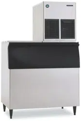
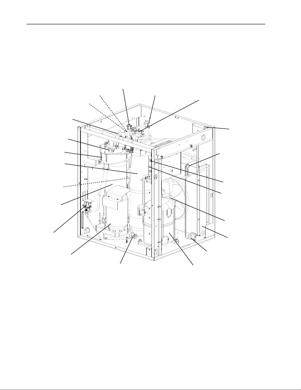
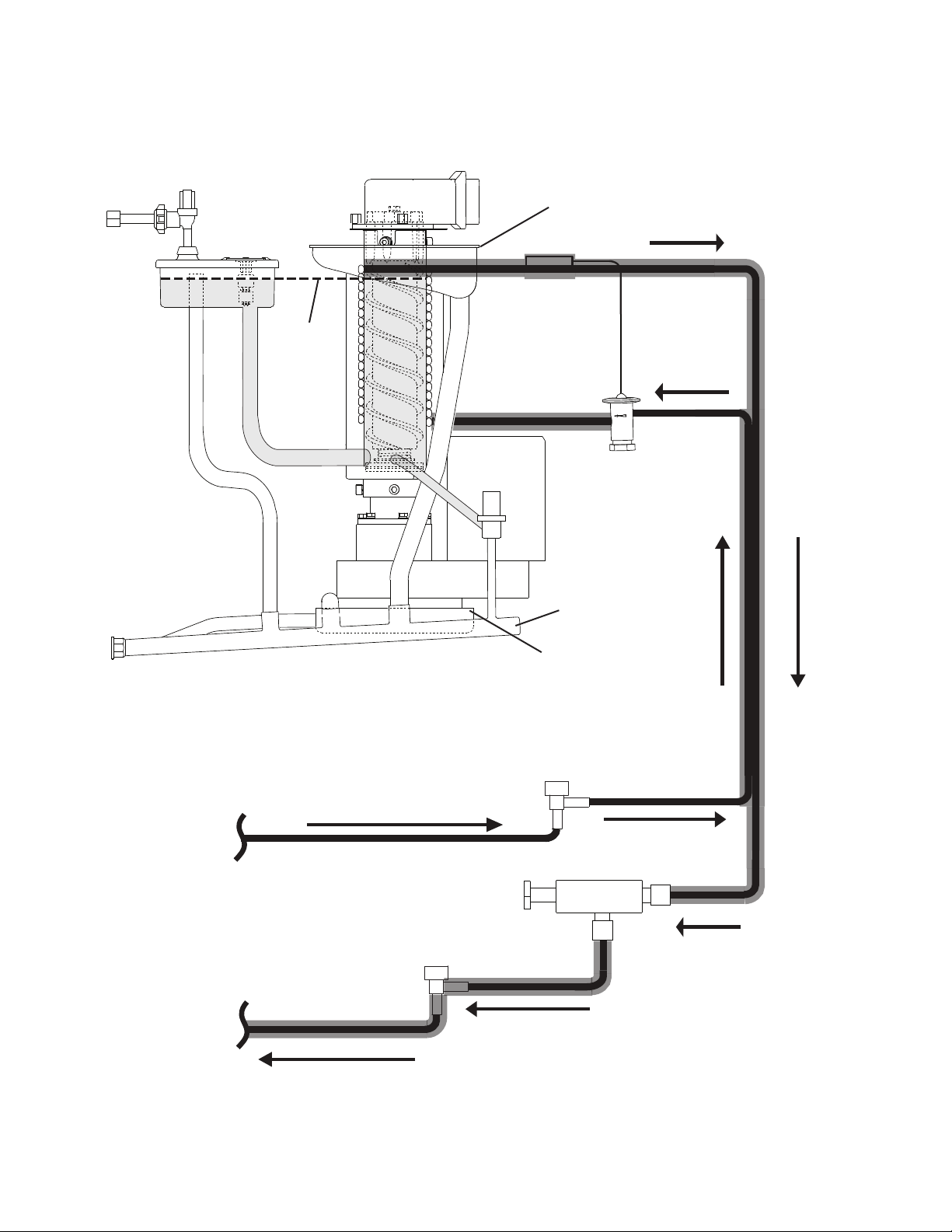
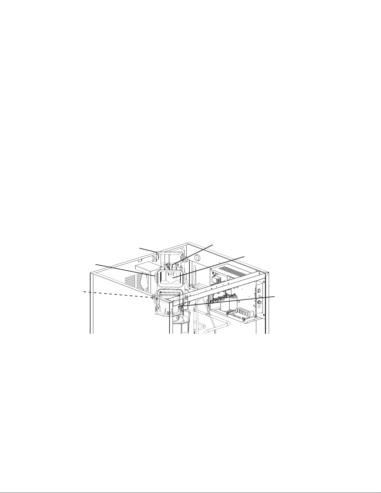
I. Construction and Water/Refrigeration Circuit Diagram
A. Construction
1. Air-Cooled Models
Model Shown: F-1501MAH
Inlet Water Valve
Reservoir
Bin Control 2
(Mechanical)
(If Applicable)
Spout
Evaporator
Gear Motor
Compressor
Drain Valve
Fan Motor
Ice Chute
Junction Box
Float Switch
High-Pressure Switch
Condenser
Bin Control 1
(Infrared Sensor)
Thermostatic
Expansion Valve
Control Switch
Power Switch
Drier
Water Supply Inlet
Drip Pan
Evaporator
Heater (-C)
9
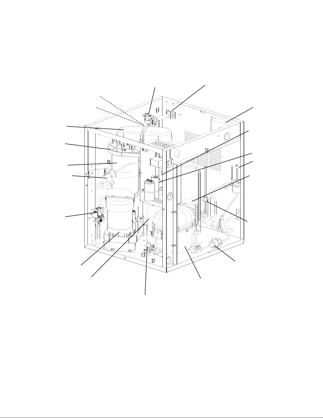
2. Water-Cooled Models
Model Shown: FD-650MWH-C
Inlet Water Valve
Reservoir
Power Switch
Bin Control 1
(Infrared Sensor)
Spout
Evaporator
Gear Motor
Compressor
Drain Valve
Float Switch
Junction Box
Water-Cooled
Condenser
Thermostatic
Expansion Valve
Ice Chute
Water Regulating
Valve
High-Pressure Switch
Drier
Control Switch
Water Supply Inlet
Drip Pan
10
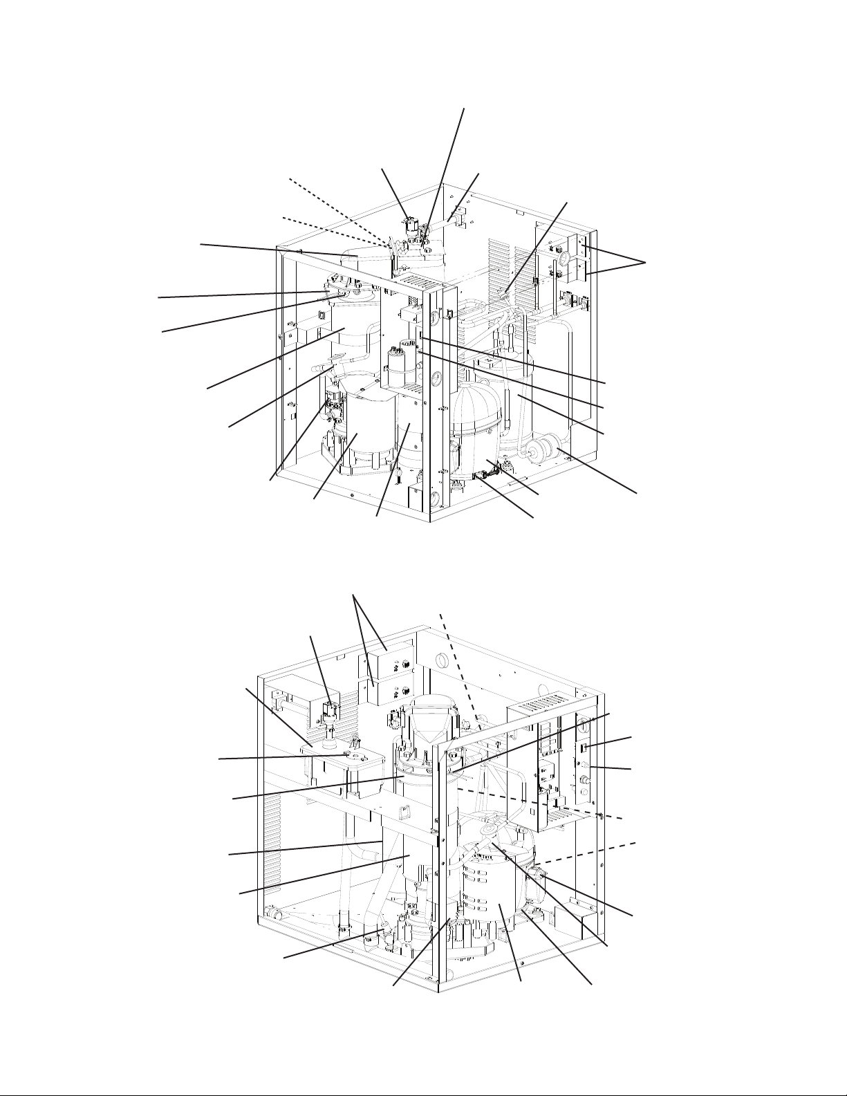
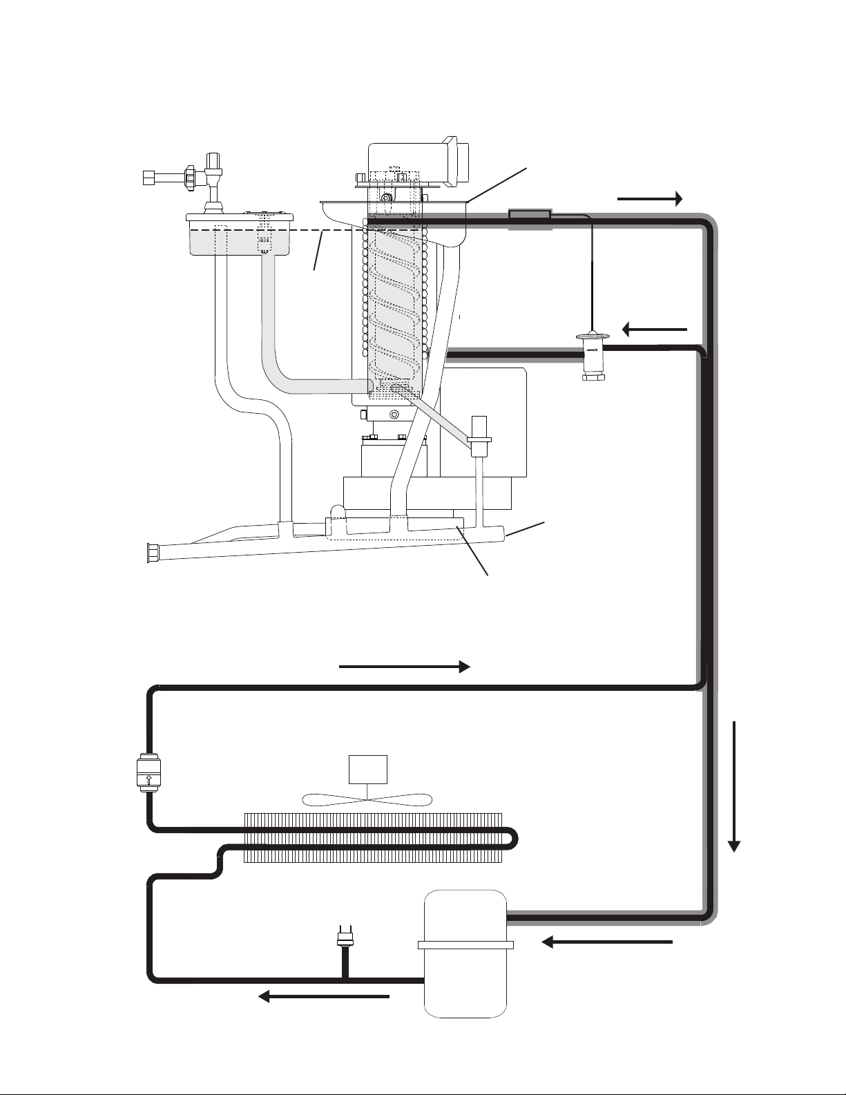
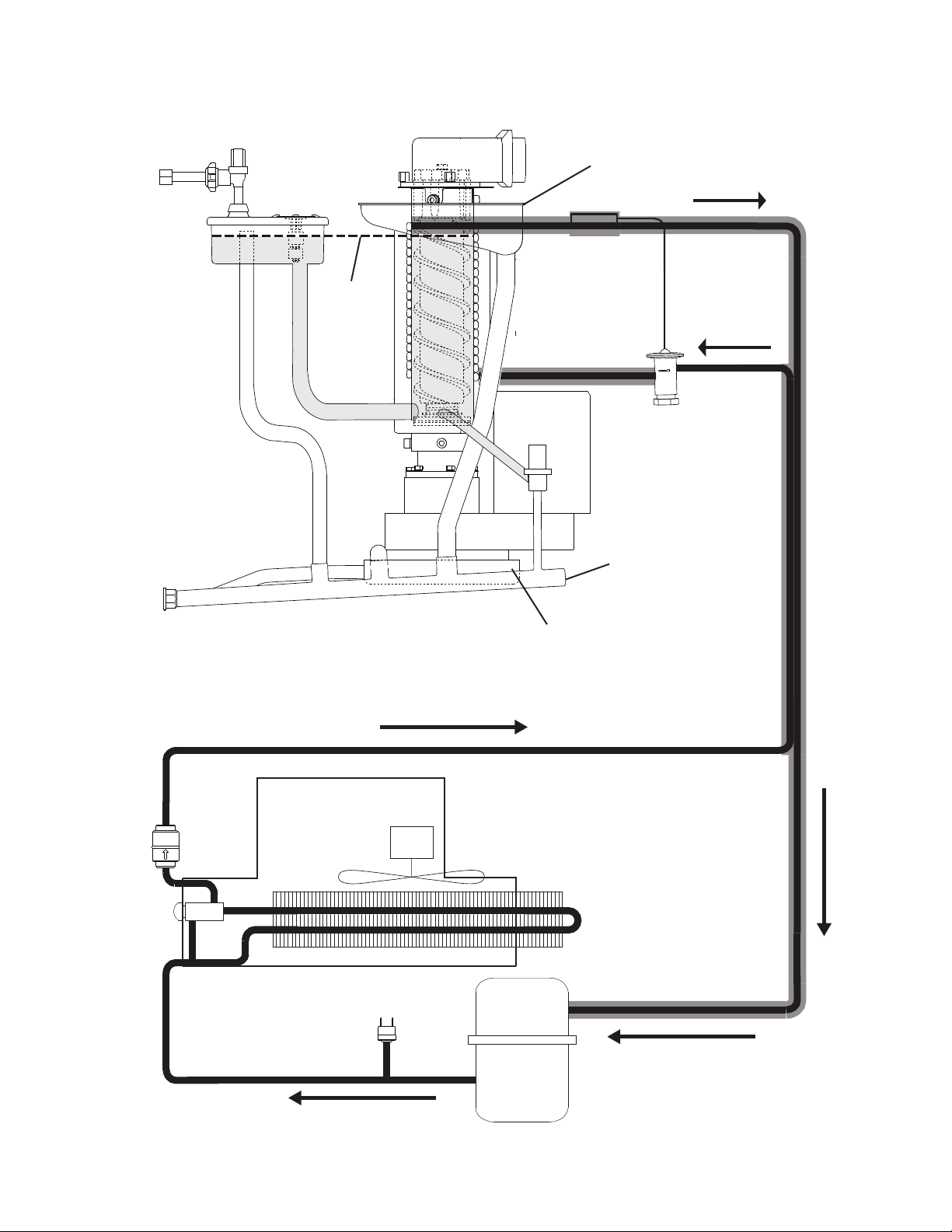
3. Remote Air-Cooled Models
Model Shown: F-1001MRH-C
Inlet Water Valve
Reservoir
Spout
Evaporator
Gear Motor
Compressor
Drain Valve
Evaporator
Heater (-C)
Float Switch
Junction Box
Thermostatic
Expansion Valve
Ice Chute
High-Pressure Switch
Drier
Water Supply Inlet
Crankcase
Heater
Reciever
Power Switch
Control Switch
Drip Pan
Model Shown: F-1001MRJ-C
Inlet Water Valve
Reservoir
Bin Control
(Infrared Sensor)
Spout
Evaporator
Gear Motor
Compressor
Drain Valve
Evaporator
Heater (-C)
Float Switch
Junction Box
Thermostatic
Expansion Valve
Ice Chute
High-Pressure Switch
Drier
Water Supply Inlet
Crankcase
Heater
Reciever
Power Switch
Control Switch
Drip Pan
Bin Control 2
(Mechanical)
(If Applicable)
11
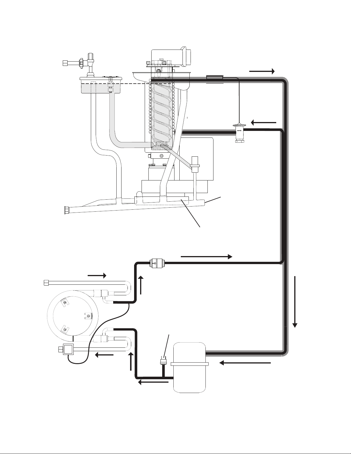
4. Low-Side, Parallel Rack System Models
Liquid Line Valve
Inlet Water Valve
Reservoir
Spout
Evaporator
Gear Motor
Drain Valve
Evaporator
Heater (-C)
Float Switch
Thermostatic
Expansion Valve
Ice Chute
Water Supply Inlet
Evaporator Pressure
Regulator Valve (EPR)
Power Switch
Control Switch
Suction Line Valve
Model Shown: F-2001MLH
Bin Control 1
(infrared sensor)
Bin Control 2
(Mechanical)
(If Applicable)
12
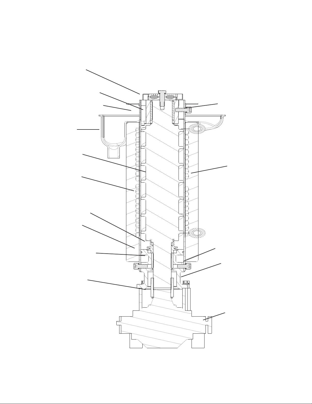
B. Icemaking Unit
Model Shown: F-1501MAH
Seal Bolt
Gear Motor
Spline Coupling
Lower Housing
O-Ring
Mechanical-Seal
Cylinder
Auger
Extruding Head-Upper Bearing
Cutter
Insulation
Socket Head Cap Screw
with Split Lock Washer
Hex Bolt and Washer
Evaporator Heater (-C Models)
Drip Pan
13
C. Water/Refrigeration Circuit Diagram
1. Air-Cooled Models
Drier
Condenser
Condenser
Fan Motor
High Pressure
Switch
Compressor
Overow
Reservoir
Drain
Valve
Thermostatic
Expansion Valve
Spout
Water Level
Evaporator
Float
Switch
Inlet Water Valve
Water Supply
Line
Gear Motor Drain Pan
Drain Outlet
Insulation
Evaporator Condensate
Drain Pan (Drip Pan)
Gear Motor
Drain Hose
14
2. Water-Cooled Models
Water Supply
Line
Water Supply Line
Drain Outlet
Condenser
Water Regulating Valve
Drier
Thermostatic
Expansion Valve
Insulation
Evaporator Condensate
Drain Pan (Drip Pan)
Spout
Float
Switch
Inlet Water Valve
Reservoir
Water Level
Evaporator
Overow
Drain
Valve
Gear Motor
Drain Outlet
Gear Motor Drain Pan
High-Pressure
Switch
Compressor
Drain Hose
15
3. Remote Air-Cooled Models
Drier
Remote Condenser
Condenser Fan Motor
High-Pressure
Switch
Compressor
Overow
Reservoir
Drain
Valve
Thermostatic
Expansion Valve
Spout
Water Level
Evaporator
Float
Switch
Inlet Water Valve
Water Supply
Line
Gear Motor Drain Pan
Drain Outlet
Insulation
Evaporator Condensate
Drain Pan (Drip Pan)
Gear Motor
Drain Hose
16
4. Low-Side, Parallel Rack System Models
Overow
Reservoir
Drain
Valve
Thermostatic
Expansion Valve
Spout
Water Level
Evaporator
Float
Switch
Inlet Water Valve
Water Supply
Line
Gear Motor Drain Pan
Drain Outlet
Insulation
Evaporator Condensate
Drain Pan (Drip Pan)
Gear Motor
Liquid Line Valve
Suction Line Valve
Evaporator Pressure Regulator (EPR Valve)
From Rack System
To Rack System
Drain Hose
NOTICE! F-1001MLH Use only with R-404A
F-1002MLJ Use only with R-404A, R-407A, or R-407F
EPR Settings:
F-1001MLH: R-404A EPR Setting: 31 PSIG
F-1002MLJ: R-404A EPR Setting: 31 PSIG
R-407A EPR Setting: 22 PSIG
R-407F EPR Setting: 23 PSIG
17
II. Sequence of Operation and Service Diagnosis
A. Sequence of Operation Flow Chart
1. Icemaking and Drain Cycle
1-in-1 drain cycle. DV opens for 2 sec. every hour
(CB S1 Dip Switch 4).
Icemaker status does not change.
Control Board Sequence of Operation Flow Chart - Icemaking and Drain Cycle
LFS closed
UFS closed
FZT starts
FT terminated
WV de-energized
3. 1-in-12 Drain Cycle
& Restart (optional)
UFS open
LFS open (WV on)
FT starts (90 sec.)
FZT terminated
WV energized
Comp continues
GM continues
FM continues
FMR continues
LLV continues
SLV continues
1. Startup
2. Ice Purge Cycle
WV energized
Comp energized
LLV energized
SLV energized
GM continues
FM continues
FMR continues
2. 1-in-1 Drain Cycle
Comp de-energized
LLV de-energized
SLV de-energized
GM continues
FM continues
FMR continues
1. Fill Cycle
3. Freeze Cycle
LFS closed
UFS closed
FZT starts (30
min.)
FT terminated
WV de-energized
Comp continues
GM continues
FM continues
FMR continues
LLV continues
SLV continues
Low Water Safety
Purge Timer
UFS open
WV energized
Comp de-energized
LLV de-energized
SLV de-energized
GM continues
FM continues
FMR continues
DV energized
GM de-energized
FM de-energized
FMR de-energized
10-min. DT terminated
DV de-energized
1-in-12 DT reset
5 min.
4. Icemaker Restart
2. Ice Purge Cycle
3. 10-Min. Drain
If Fill > 90 sec. FT
1-beep alarm sounds
WV continues
When UFS closes
alarm resets and
2. Ice Purge Cycle starts.
FT Maximum
90 sec.
4. 1-in-12 Drain Cycle - Although the factory default 1-in-1 drain cycle
is recommended, a 1-in-12 drain cycle is available. For 1-in-12 drain
cycle sequence, see "3. 1-in-12 Hour Drain Cycle & Restart (optional)."
Rell
FT Maximum
90 sec.
90 sec. FT exceeded,
90 sec. PT starts and
1-beep alarm sounds
90. sec. PT terminates
unit shuts down and
1-beep alarm continues.
When UFS closes, alarm
resets and 2. Ice Purge
Cycle starts.
WV continues
GM de-energized
FM de-energized
FMR de-energized
1. DT Initiates DC
To bypass, press the
"SERVICE" button after
GM starts.
5 min.
to "1. Fill Cycle" above
90 sec.
(CB S1 dip switch 4 "ON")
FT off (90 sec.)
5 or 30 sec.
(S1 Dip Switch 7)
EH energized
GM energized
FM energized
FMR energized
1. DT Initiates DC
Continued uninterrupted
operation
DV energizes for 2 sec.
2. Continued Operation
DV de-energizes, no
interruption in ice production
30-min. FZT
Startup
FZT exceeded (LFS does not
open): CB shuts down icemaker
and sounds a 5-beep alarm.
Legend:
BC-bin control (mechanical stand-alone)
BC1-bin control 1 (infrared sensor)
BC2-bin control 2 (mechanical backup)
CB-control board
Comp-compressor
DC-drain cycle
DT-drain timer
DV-drain valve
EH-evaporator heater
FM-fan motor
FMR-fan motor-remote
FT-ll timer (low water safety)
FZT-freeze timer
GM-gear motor
LFS-lower oat switch
LLV-liquid line valve (MLH)
PT-purge timer
SLV-suction line valve (MLH)
UFS-upper oat switch
WV-inlet water valve
Low Water Safety
Shutdown
(CB S1 dip switch 4 "OFF")
Normal Operation
Power Switch "ON"
Control Switch in "ICE"
POWER OK LED on
BC1 Green LED on
BC1 Yellow LED off
BC(2) Closed
18
2. Shutdown
3. Icemaker Off
1. BC1 Shutdown (infrared sensor)
1. Bin Full
BC1 activated
Comp de-energized
LLV de-energized
SLV de-energized
GM continues
FM continues
FMR continues
GM de-energized
FM de-energized
FMR de-energized
2. Ice Purge Cycle
BC1 Yellow LED (ashing or steady)
BC1 delay determined by CB S1 dip
switch 1, 2, 3
4. Icemaker Restart
5 min.
Note for models with BC1 and BC2:
If BC1 fails to shutdown the icemaker, BC2
opens and a 9-beep alarm sounds. See
"II.D. Bin Control Check."
BC1 Green LED on
BC1 Yellow LED off
BC1 Green LED on
BC1 Yellow LED off
BC1 de-activated
Control Board Sequence of Operation Flow Chart - Shutdown
1. Bin Full
6 to 10 sec.
All Components
de-energized
BC(2) closed
(BC paddle and proximity
switch disengaged)
BC2
to "2. Ice Purge Cycle" in Icemaking
and Drain Cycle Chart
BC(2) open
BC paddle and
proximity switch
engaged
2. Icemaker Off 3. Icemaker Restart
Ice level lowered
2. BC(2) Shutdown (mechanical)
Legend:
BC-bin control (mechanical stand-alone)
BC1-bin control 1 (infrared sensor)
BC2-bin control 2 (mechanical backup)
CB-control board
Comp-compressor
FM-fan motor
FMR-fan motor-remote
GM-gear motor
LLV-liquid line valve (MLH)
SLV-suction line valve (MLH)
Note for models with BC1 and BC2:
When BC2 is activated, a 9-beep alarm
sounds. See "II.D. Bin Control Check."
BC
Immediate
to "2. Ice Purge Cycle"
in Icemaking and Drain
Cycle Chart
19
B. Service Diagnosis
WARNING
• The appliance should be diagnosed and repaired only by qualied service
personnel to reduce the risk of death, electric shock, serious injury, or re.
• Risk of electric shock. Use extreme caution and exercise safe electrical practices.
• Moving parts (e.g., fan blade or auger) can crush and cut. Keep hands clear.
• CHOKING HAZARD: Ensure all components, fasteners, and thumbscrews are
securely in place after the appliance is serviced. Make sure that none have fallen
into the dispenser unit/ice storage bin.
• Make sure all food zones in the icemaker and dispenser unit/ice storage bin are
clean after service.
1. Ice Production Check
To check production, prepare a bucket or pan to catch the ice and a set of scales to
weigh the ice. After the appliance has operated for 10 to 20 min., catch the ice production
for 10 min.. Weigh the ice to establish the batch weight. Multiply the batch weight by
144 for the total production in 24 hours. When conrming production or diagnosing
low production, reference production information found in "VII.A. Specication and
Performance Data."

20
2. Diagnostic Procedure
This diagnostic procedure is a sequence check that allows you to diagnose the electrical
system and components. Before proceeding, check for correct installation, proper voltage
per appliance nameplate, and adequate water pressure (10 PSIG to 113 PSIG).
Note: • When checking high voltage (115VAC), always choose a neutral (W) wire to
establish a good neutral connection.
• When checking low voltage (24VAC), always choose a neutral (LBU) wire to
establish a good neutral connection.
• When checking control board DC voltage (5VDC), always place the red positive
test lead from the multimeter to CB K5 pin closest to CB K4 connector.
See "II.C. Control Board Check."
• When checking BC1 (infrared sensor) (20VDC), check that the infrared sensor
green LED is on. This green LED conrms 20VDC power from CB K6to the
infrared sensor and remains on constantly. If green LED is not on, check for
20VDC from CB K6 #1 (DBU) to CB K6 #3 (BR). See "II.D. Bin Control Check."
• To speed up the diagnostic process, the 5-min. ice purge cycle may be bypassed
by pressing the "SERVICE" button on the control board after the gear motor
starts. WARNING! Risk of electric shock. Care should be taken not to touch
live terminals.
• If the icemaker is in alarm, see "III.A.2. LED Lights and Audible Alarm Safeties."
• FM/FMR and EH (-C model except FD-650) energize when "GM" LED turns on.
• MLH Model: CB X1 relay energizes LLV and SLV.
• CB monitors the following switches with 5VDC during the icemaking process:
Control Switch (CS), High-Pressure Switch (HPS), Float Switch (FS),
Compressor Control Relay/Gear Motor Protect Relay (CCR/GMPR), and Bin
Control (2) (mechanical stand-alone or backup). When 5VDC is present across
any of these switches, the switch is open.
1) Remove the front panel, then move the power switch to the "OFF" position. Move the
control switch to the "DRAIN" position, then move the power switch back to the "ON"
position. Replace the front panel in its correct position.
2) Allow the water system to drain for 5 min.
3) Remove the front panel. Move the power switch to the "OFF" position, then turn off the
power supply.
4) Remove the control box cover and access CB.
5) Check the CB S1 dip switch settings, see "III.B.1. Default Dip Switch Settings" to assure
that they are in the correct positions. For proper operation of BC1 (infrared sensor),
conrm that S1 dip switch 7 is in the "ON" position.

21
6) Startup–CB "POWER OK" LED is on. Turn on the power supply, then move the power
switch to the "ON" position. Make sure the control switch is in the "ICE" position.
CB "POWER OK" LED and IS (BC1 if applicable) green LED turn on.
Diagnosis CB "POWER OK" LED: Check that CB "POWER OK" LED is on. Ifnot,
check for 115VAC at control transformer brown (BK on 115VAC models (except
FD-650M_H-C) and BR on 208/230VAC models and 115VAC FD-650M_H-C) wire to
neutral (W). If 115VAC is not present, check the power switch and breaker. If 115VAC
is present, check control transformer continuity. Replace as needed. Next, check for
24VAC at control transformer red (R) wire to neutral (LBU). If 24VAC is not present,
check control transformer continuity. Replace as needed. If24VAC is present, check
24VAC 1A fuse. If fuse is good, check for 24VAC at CB K8 #1 (W/R) to CB K8 #2 (LBU).
If 24VAC is present and "POWER OK" LED is off, replace CB.
Diagnosis BC(2) (mechanical stand-alone or backup): Check that the actuator
paddle is properly positioned. Check continuity across BC(2). If open, replace BC(2).
Next, check VDC at CB K8#3(GY) to CB K8 #4 (GY). When BC(2)is closed 0VDC is
read. Move the actuator paddle to open BC(2). When open, 5VDCis present between
CB K8 #3 (GY) and CB K8#4(GY). If 5VDC is not present when BC(2) is open, replace
CB. Return actuator to its normal position.
Diagnosis BC1 (infrared sensor): If "POWER OK" LED is on and BC1 green LED
is off, check 20VDC at CB K6 #1 (DBU) to CB K6 #3 (BR). If 20VDC is not present,
conrm dip switch 7 is in the "ON" position. If dip switch 7 is in the "ON" position and
20VDC is not present, replace CB. If BC1 yellow LED is on or ashing, move ice away
from lens. If no ice is present, clean the lens with a warm, clean damp cloth. If cleaning
the lens does not work, replace BC1.
7) Fill Cycle – "WTRIN" LED is on. Reservoir is empty and LFS and UFS are open.
90-sec. FT starts. WV energizes and ll cycle starts. LFS closes. Nothing occurs at this
time. Reservoir continues to ll until UFS closes. When UFS closes, WV de-energizes,
90-sec. FT is terminated, and CB "WTRIN" LED turns off. 30-min. FZTand 30-sec.
GM delay timer start. IfUFS remains open longer than 90 sec. after LFS opens,
FTexceeded and CB sounds a 1-beep alarm. WVremains energized until UFS closes.
Alarm resets automatically when UFS closes. Diagnosis: If reservoir is empty and
"WTRIN" LED is off, conrm LFS status. See "II.E.1. Float Switch Check." IfLFS is open
and "WTRIN" LED is off, replace CB. If "WTRIN" LED is on, check that the reservoir lls.
If not, check water supply line shut-off valve, water lters, and WVscreen. If "WTRIN"
LED is on and WV is off, check CB K2 #8(O) to a neutral (LBU) for 24VAC. If24VAC is
not present, check CB K2 #9(W/R) to a neutral (LBU) for 24VAC. If 24VAC is present
on CB K2 #9(W/R)and not on CB K2 #8 (O), replace CB. If 24VAC is present on
CB K2 #8(O), check continuity through WV solenoid. If open, replace WV. If WV is
energized and rell exceeds FT with no water in the reservoir, check for DV leaking.
Ifreservoir is full and overowing check for open UFS. See "II.E.1. Float Switch Check."
If UFS is closed, check that WV de-energizes. If not, check CB K2 #8 (O) to a neutral
(LBU) for 24VAC. If 24VAC is present, replace CB. IfWV de-energizes and water
continues to ll the reservoir, replace WV.

22
8) Ice Purge Cycle – "GM" LED is on. 30-sec. GM delay timer terminates. GM,
CCR/GMPR, FM/FMR, and EH (-C model except FD-650) energize. Once CCR/GMPR
energizes, 5VDC circuit closes through CCR/GMPR terminal #3 (W/O) and terminal
#5 (W/O) and CB K9 #5 (W/O) and K9 #6 (W/O). After 5VDC circuit closes, 5-min.
ice purge timer starts. Tobypass the 5-min. Ice Purge Cycle, press the "SERVICE"
button on CB after the "GM" LED turns on. WARNING! Risk of electric shock. Care
should be taken not to touch live terminals. Diagnosis: If "GM" LED is off, check
that UFS closes and WV de-energizes. IfUFS is closed, 30 sec. has passed, and "GM"
LED remains off, replace CB. If"GM" LED is on and GM is off, check CB K1 #2 (BK
or BR) to a neutral (W) for 115VAC. If115VAC is not present, check 115VAC power
supply. If115VAC is present, check CB K1 #3(BK, P, or R) to a neutral (W). If 115VAC
is present on CB K1 #2 (BK or BR) and not on CB K1 #3 (BK, P, or R), replace CB.
If115VAC is present on CB K1#3 (BK, P, or R), check GM fuse, GM internal protector,
GM windings and capacitor, and GM coupling between auger and GM. When GM
energizes,
CCR/GMPR energizes starting 5-min. ice purge timer. If FM/FMR does not start, check
FM/FMR capacitor, FM/FMR windings, and FM/FMR bearings.
9) Freeze Cycle – "COMP" and "GM" LEDs are on. The 5-min. ice purge timer
terminates. GM, EH, CCR, and FM/FMR continue. Comp or LLV/SLV (MLH model)
energize. Ice production starts 4to 6 min. after Comp or LLV/SLV (MLH model) energize
depending on ambient and water conditions. As ice is produced, the water level in
the reservoir drops. UFS opens. Nothing happens at this time. When LFS opens, WV
energizes and rell cycle begins, FZT terminates, and FTstarts.
FZT: 30-Min. Freeze Safety Timer – FZT starts when UFS closes and terminates
when LFS opens. If LFS does not open within 30 min. of UFS closing, CB shuts down
the icemaker and sounds a 5-beep alarm. See "III.A.2.LED Lights and Audible Alarm
Safeties." To reset, turn the power supply off and on again. See "II.F. Diagnostic Tables"
for troubleshooting details.
Icemaker Diagnosis (CCR/GMPR): 5-min. ice purge timer terminates, CB "COMP"
LED is on and COMP or LLV/SLV (MLH model) energizes. If not, check for 5VDC
between CB K5 connector pin closest to CB K4 connector and CB K9connector
#5(W/O). If 5VDC is not present, replace CB. If 5VDC is present, check for 5VDC
between CB K5 connector pin closest to CB K4 connector and CB K9connector
#6(W/O). If 5VDC is present and CB "Comp" LED is off (CR, COMP, or LLV/SLV (MLH
model) not energized), replace CB. If 5VDC is not present, check for 115VAC between
CCR/GMPR terminal #7(O) to CCR/GMPR terminal #8(W) for 115VAC. If115VAC
is not present (GM not energized), see step 8 above. If 115VAC is present and CCR/
GMPR contacts are open (5VDCpresent between terminals #3(W/O) and #5(W/O)),
check CCR/GMPR solenoid voltage and solenoid continuity. Replace CCR/GMPR if
necessary.
Icemaker Diagnosis (COMP or LLV/SLV (MLH model)): If"COMP" LED is on and
COMP or LLV/SLV (MLH model) is not energized, check CB X1 relay BK or BR wire to
a neutral (W) and CB X1 relay V, BR, or R wire to a neutral (W) for 115VAC. If115VAC
is present on CB X1BK or BR wire and not on CBX1 V, BR, or R wire, replace CB.
If115VAC is present on CBX1V, BR, or R wire and COMP or LLV/SLV (MLH model) is
not energized, check for 115VAC at CB X1 Comp relay, Comp or LLV/SLV (MLH model).
Check Comp internal overload (motor protector), start relay, and capacitors.
Check LLV/SLV (MLH model) solenoid continuity.

23
10) Rell Cycle – "GM", "COMP", and "WTRIN" LEDs are on.
LFS opens. WVenergizes and 90-sec. FT starts. Comp or LLV/SLV (MLH model), GM,
CCR/GMPR, and FM/FMR continue. LFS closes. Nothing occurs at this time. Reservoir
continues to ll until UFS closes. When UFS closes, WV de-energizes, 90-sec. FT
terminates, and 30-min. FZT starts. If UFS remains open longer than 90 sec. after LFS
opens, FT exceeded and CB sounds a 1-beep alarm. WVremains energized until UFS
closes. Alarm resets automatically when UFS closes.
Diagnosis – Conrm that the water level has dropped and the UFS and LFS are open.
See "II.E.1. Float Switch Check." Check that "WTRIN" LED is on. IfLFS is open and
"WTRIN" LED is off, replace CB. If "WTRIN" LED is on, check that the reservoir lls.
Ifnot, check water supply line shut-off valve, water lters, and WVscreen. If"WTRIN"
LED is on and WV is off, check CB K2 #8(O) to a neutral (LBU) for 24VAC. If 24VAC
is not present, check CB K2 #9(W/R) to a neutral (LBU) for 24VAC. If 24VAC is
present on CB K2 #9 (W/R)and not on CB K2#8 (O), replace CB. If 24VAC is
present on CB K2#8(O),check continuity through WV solenoid. If open, replace WV.
IfWV is energized and rell exceeds FT with no water in the reservoir, check for DV
leaking. Ifreservoir is full and overowing check for open UFS. See "II.E. Float Switch
Check and Cleaning." If UFS is closed, check that WVdeenergizes. If not, check
CB K2 #8(O) to a neutral (LBU) for 24VAC. If 24VAC is present, replace CB. If WV
de-energizes and water continues to ll the reservoir, replace WV.
Note: Each time UFS closes, 30-min. freeze timer starts. The 30-min. freeze timer
resets when UFS closes again. If UFS does not close again within 30 min., CB
shuts down the unit and sounds a 5-beep alarm every 5 sec.
See "III.A.2 LED Lights and Audible Alarm Safeties."
FT: 90-Sec. Low Water Safety Timer – When LFS opens, 90-sec. low water safety
timer starts. If UFS does not close within 90 sec. after LFS opens (FTexceeded),
CBsounds a 1-beep alarm and a 90-sec. shutdown cycle starts
See "III.A.2.LED Lights and Audible Alarm Safeties." Comp or LLV/SLV (MLH model)
de-energizes. GM, CCR/GMPR, and EH continue. 90-sec. purge timer terminates, GM,
EH, and CCR/GMPR de-energize. WV and 1-beep alarm continue until UFS closes.
11) Drain Cycle
a) 1-in-1 Drain Cycle: DV energizes once every hour when the 1-in-1 drain cycle is
activated (S1 dip switch 4 in the "OFF" position (factory default position)). GM,
FM/FMR, Comp, LLV/SLV (MLH model), continue. DV energizes for 2 sec. every
hour. This setting is recommended for optimum icemaker performance. The 1-in-1
drain cycle allows any sediment to drain from the evaporator without interrupting the
icemaking process.
b) 1-in-12 Drain Cycle (optional): DV energizes once every 12 hours when the 1-in-12
drain cycle is activated (S1 dip switch 4 in the on position (optional)). 12-hour drain
cycle timer terminates, Comp or LLV/SLV (MLH model) de-energize. GM, and
FM/FMR continue. The 5-min. ice purge timer starts. When the 5-min. ice purge
timer terminates, GM and FM/FMR de-energize. 10-min. DT starts, DV energizes.
After 10-min. DT terminates, DV de-energizes icemaking process restarts and 12-
hour drain cycle timer starts.

24
c) Manual Drain: Manual drain is used when servicing evaporator components and
cleaning and sanitizing the unit. When the unit is making ice and the control switch
is moved to the "DRAIN" position, there is a 3-sec. delay, then Comp or LLV/SLV
(MLH models) de-energize and the 5-min. ice purge timer begins. When the 5-min.
ice purge timer terminates, GM, and FM/FMR de-energize. DV energizes to drain
the evaporator and reservoir. To avoid the 5-min. shutdown delay, turn off the power
supply, then move the control switch to the "DRAIN" position. Turn on the power
supply. DV energizes to drain the evaporator and reservoir. DV de-energizes when
the control switch is moved to the "ICE" position.
10) Shutdown
a) BC1 (infrared sensor): When power is supplied to the icemaker, the green LED on
BC1 turns on. The green LED remains on constantly. As ice lls the storage bin to
the level of activating BC1, BC1 yellow LED turns on (ashing or steady). The yellow
LED ashes when ice is at the outer limit of its range and turns steady as ice nears.
After the yellow LED turns on (ashing or steady), BC1 shutdown delay timer (S1 dip
switch 1, 2, 3) starts. For a typical dispenser unit application, a 100-sec. shutdown
delay is recommended. When used with a standard Hoshizaki storage bin, any
shutdown delay setting is acceptable. See "III.B.2. BC1 (Infrared Sensor) Shutdown
Delay (S1 dip switch 1, 2, 3)." Once BC1 shutdown delay timer terminates, Comp or
LLV/SLV (MLH models) de-energize and the 5-min. ice purge timer starts. When
the 5-min. ice purge timer terminates, GM, CCR/GMPR, and FM/FMR de-energize.
Diagnosis: See "II.D.1. Bin Control 1 (infrared sensor) Check."
Note: When BC1 and BC2 are applied–If BC1 fails to shut down the icemaker, BC2
opens, CB shuts down the icemaker and sounds a 9-beep alarm.
b) BC(2) (mechanical stand-alone or backup):
BC (stand-alone): BC opens (actuator paddle engaged). CB shuts down the
icemaker within 10 sec.
BC2 (backup): BC2 opens (actuator paddle engaged). CB shuts down the icemaker
immediately and sounds a 9-beep alarm.
Diagnosis: See "II.D.2. Bin Control(2) (mechanical stand-alone or backup) Check."
Legend: BC1–bin control 1 (infrared sensor); BC(2)–bin control (2) (mechanical stand-alone
or backup); CB–control board; CCR–compressor control relay (formerly GMPR
gear motor protect relay); Comp–compressor; DV–drain valve; EH–evaporator
heater (-C model except FD-650); FM–fan motor; FMR–fan motor-remote;
GM–gear motor; GMR–gear motor relay; LFS–lower oat switch; LLV –liquid line
valve (MLH model); S LV–suction line valve (MLH model); UFS–upper oat switch;
WV–inlet water valve
25
C. Control Board Check
Before replacing a control board that does not show a visible defect and that you suspect
is bad, always conduct the following check procedure. This procedure will help you verify
your diagnosis.
1) Check CB S1 dip switch settings to assure that they are in the factory default position.
For factory default settings, see "III.B.1. Default Dip Switch Settings."
Note: S1 dip switch 7determines bin control application:
BC (mechanical stand-alone) or BC2 (mechanical backup only): S1 dip switch 7 in
the "OFF" position.
BC1 (infrared sensor stand-alone) or with BC2 (mechanical backup): S1 dip switch
7in the "ON" position.
2) Move the power switch to the "ON" position and move the control switch to the "ICE"
position. The "POWER OK" LED turns on. Diagnosis "POWER OK" LED: Check that
the CB "POWER OK" LED is on. If not, check for proper supply voltage (115VAC) input
to the control transformer (power switch, breaker, and fuse). Next, check for proper
low-voltage (24VAC) output from the control transformer and that the 1A fuse is good.
Check for 24VAC at CB K8 #1 (W/R) to CB K8 #2 (LBU). If 24VAC is present and the
"POWER OK" LED is off, replace CB.
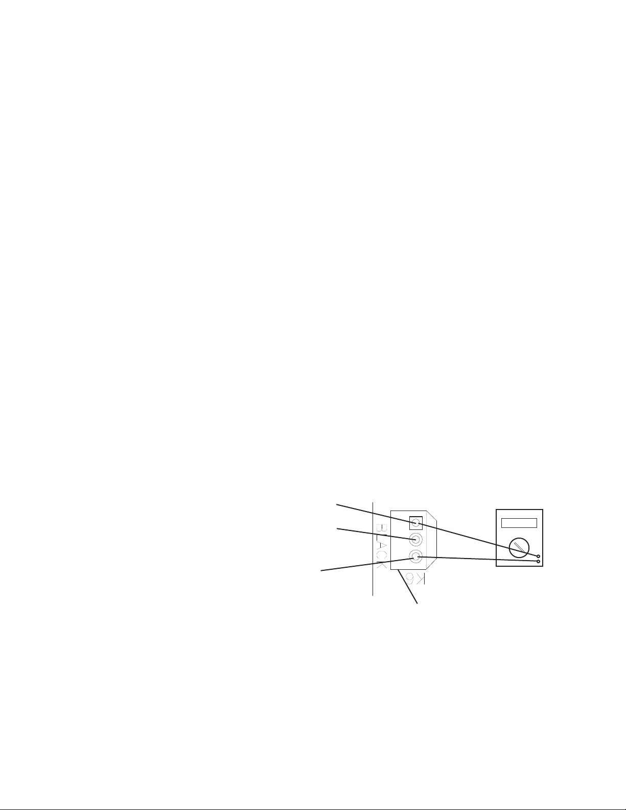
3) BC1 (infrared sensor) Power Supply (K6 connector): CB supplies 20VDC to BC1
and BC1 green LED is on. Diagnosis: Check that BC1 green LED is on. If not, check
for 20VDC between CB K6 #1 (DBU) and CB K6 #3(BR). See Fig. 1. If 20VDC is not
present, replace CB. If 20VDC is present, conrm that the yellow LED is not ashing
or steady. If BC1 yellow LED is on or ashing, move ice away from lens. If no ice is
present, clean the lens with a warm, clean damp cloth. If cleaning the lens does not
work, replace BC1 (infrared sensor).
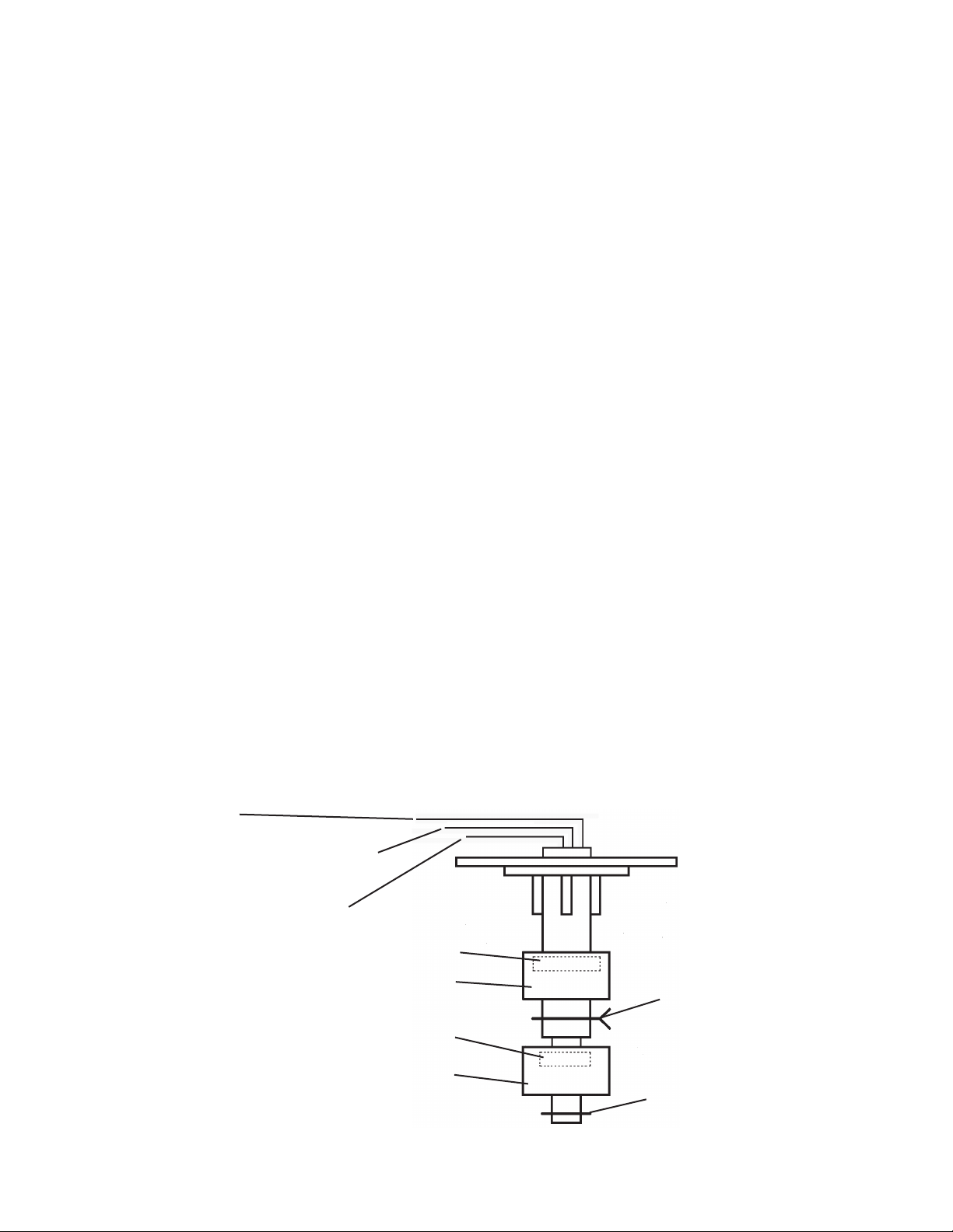
Fig. 1
Red Positive
Test Lead
Black Negative
Test Lead
20VDC
Multimeter
3
2
1
K6 #3
Brown (BR)
K6 #2
White (W)
K6 #1
Dark Blue (DBU)
• K6 Connector
BC1 (Infrared Sensor)
BC1 (infrared sensor) (20VDC)
Open (yellow LED ashing or steady)
20VDC K6 #1 (DBU) to K6 #3 (BR)
0VDC K6 #1 (DBU) to K6 #2 (W)
20VDC K6 #2 (W) to K6 #3 (BR)
BC1 (infrared sensor) (20VDC) Closed
20VDC K6 #1 (DBU) to K6 #3 (BR)
20VDC K6 #1 (DBU) to K6 #2 (W)
0VDC K6 #2 (W) to K6 #3 (BR)
26
4) 5VDC Output Checks:
CB K9 Connector: Control Switch (CB K9 #1 and #2) (open contacts for icemaking,
closed contacts for drain), High-Pressure Switch (CB K9 #3 and #4), Compressor
Control Relay/Gear Motor Protect Relay (K9 #5 and #6).
CB K8 Connector: Bin Control (2) (K8 #3 and #4) and Float Switch (K8 #5 (common),
#6 (lower), and #7 (upper)).
When checking 5VDC control voltage, always place the red positive test lead from
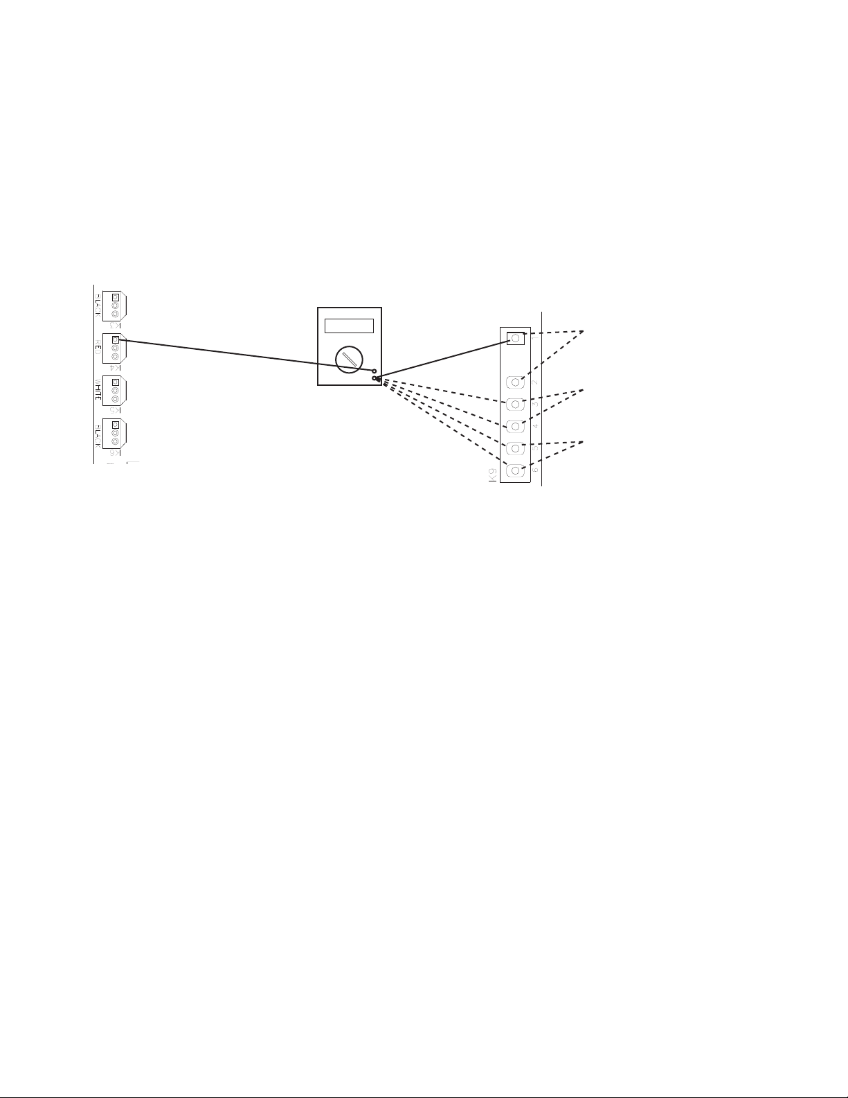
the multimeter to the CB white K5 pin closest to the CB red K4 connector. See Fig. 2.
Then place the black negative test lead from the multimeter to the corresponding pin to
complete the 5VDC check.
Red positive test lead
to K5 pin closest to K4
connector
Fig. 2
Control Board K9 Connector
Red Positive
Test Lead
Black Negative
Test Lead
Multimeter
5VDC
Control Switch
white/black (W/BK)
High-Pressure Switch
yellow (Y) wires
Compressor Control Relay/
Gear Motor Protect Relay
(terminals #3 and #5)
white/orange (W/O)
a) Control Switch – CB K9 #1 (W/BK) and CB K9 #2 (W/BK):
5VDC is present between CB white K5 connector, pin closest to CB red
K4 connector and CB K9 #1 (W/BK) at all times. If 5VDC is not present, replace
CB. When the control switch is in the "ICE" position, the control switch contacts
are open. 0VDC is present between CB white K5 connector, pin closest to CB red
K4 connector and CB K9 #2 (W/BK). When in the "ICE" position, 5VDC is present
between CB K9 #1 (W/BK) to CB K9 #2 (W/BK). When the control switch is in the
"DRAIN" position, the control switch contacts are closed. 5VDC is present between
CB white K5 connector, pin closest to CB red K4 connector, to CB K9 #1 (W/BK)
or#2(W/BK). If 5VDC is not present, replace CB. 0VDC is present from CB K9
#1(W/BK) to CB K9 #2 (W/BK).
b) High-Pressure Switch – CB K9 #3 (Y) and CB K9 #4 (Y):
5VDC is present between CB K5 connector, pin closest to CB red K4 connector and
CB K9 #3 (Y) at all times. When the high-pressure switch is closed, 5VDC is present
between CB K5 pin closest to CB K4 connector to CB K9 #3 (Y) and CB K9 #4 (Y).
If 5VDC is not present, replace CB. When the high-pressure switch is closed, 0VDC
is present at CB K9 #3 (Y) to CB K9 #4 (Y). When the high-pressure switch is open,
5VDC is present at CB K9 #3 (Y) to CB K9 #4 (Y). If the high-pressure switch is open
and CB is not in alarm, replace CB. If5VDC is present at CB K9 #3 (Y) and not at
CB K9 #4 (Y), the high-pressure switch is open and CB sounds a 3-beep alarm.
Check continuity across the high-pressure switch (CB K9 #3 (Y) and CB K9 #4 (Y)).

27
c) Compressor Control Relay/Gear Motor Protect Relay (CCR/GMPR) –
CB K9 #5(W/O) and CB K9 #6 (W/O): 5VDC is present from CB white K5 connector,
pin closest to CB red K4 connector to CB K9 #5 (W/O) at all times. If 5VDC is not
present, replace CB. When CCR/GMPR terminals #3 (W/O) and #4 (W/O) are open
(CCR/GMPR de-energized), 5VDC is present between CB K9 #5 (W/O) and CB K9
#6 (W/O). When CCR/GMPR terminals #3(W/O) and #4 (W/O) are closed (CCR/
GMPR energized), 5VDC is present between CB K9 #5 (W/O) and CB K9 #6 (W/O).
When CCR/GMPR terminals #3 (W/O) & #5 (W/O) are open CB may be in an
8-beep alarm. See "III.A.2. LED Lights and Audible Alarm Safeties."
d) Bin Control (2) (mechanical stand-alone or backup) –
CB K8 #3 (GY) and CB K8 #4(GY): 5VDC is present from CB white K5 connector,
pin closest to CB red K4 connector to CB K8 #3 (GY) at all times. If 5VDC is not
present, replace CB. When BC(2) is closed (calling for ice), 5VDC is present from
CB white K5 connector, pin closest to CB red K4 connector, to CB K8 #3 (GY) and
CB K8 #4(GY). If 5VDC is not present to either CB K8 #3 (GY) or CB K8 #4(GY),
replace CB. If 5VDC is present at CB K8 #3 (GY) and not to CB K8 #4 (GY), BC(2) is
open. See "II.D.2. Bin Control (2) (mechanical stand-alone or backup) Check."
e) Float Switch (LFS and UFS) – CB K8 #5 (BK) (common), CB K8 #6(R) (upper),
and CB K8 #7 (BU) (lower): 5VDC is present from CB white K5 connector pin closest
to CB red K4 connector to CB K8 #5(BK) (common) at all times. If not, replace CB.
5VDC is present from CB white K5 connector pin closest to CB red K4connector
to CB K8 #6 (R) (upper) and CB K8 #7 (BU) (lower) when FS is open. If 5VDC
is present between CB K8 #5 (BK) and CB K8 #6 (R) (upper) or CB K8 #7 (BU)
(lower), FS is open. Forfurther FS diagnostics, see "II.E. Float Switch Check and
Cleaning."
5) Fill "WTRIN" LED is on: 24VAC is present at CB K2 #9 (W/R) at all times. If not,
conrm 24VAC from CB K2 #9(W/R) to a neutral (LBU). When LFS open at startup
or opens during normal operation, "WTRIN" LED turns on, ll timer (FT) starts, freeze
timer (FZT) terminates (only during normal operation), and WV energizes. If LFS is
open and "WTRIN" LED is off, conrm LFS status. See "II.E. Float Switch Check and
Cleaning." If LFS is open and "WTRIN" LED is off, replace CB. If "WTRIN" LED is on
and WV is not energized, check for 24VAC at CB K2 #8(O) to a neutral (LBU). If24VAC
is not present at CB K2 #8(O), replace CB. "WTRIN" LED turns off once UFS closes.
Ifnot, conrm UFS status. See "II.E. Float Switch Check and Cleaning." IfUFS is
closed and "WTRIN" LED is on, replace CB. If "WTRIN" LED is off and WV is open,
check for 24VAC at CB K2 #8 (O). If 24VAC is present at CB K2 #8 (O), replace CB.
If24VAC is not present, check WV diaphragm.
6) Ice Purge Cycle "GM" LED is on: When UFS closes, GM delay timer starts (5 or
30sec. depending on CB S1 dip switch #7). Once GM delay timer terminates, "GM"
LED turns on, GM and EH (-C model except FD-650) energize and 5-min. ice purge
timer starts. If GM does not energize 30 sec. after UFS closes, conrm UFS status.
See "II.E. Float Switch Check and Cleaning." If UFS is closed and GM LED does not
turn, replace CB. If "GM" LED is on and GM and EH are off, check for 115VAC from
CBK1#2to a neutral (W). If 115VAC is not present, check 115VAC power supply
connections from power switch. If 115VAC is present, check for 115VAC from CB K1
#3to a neutral (W). If115VAC is present on CB K1 #2and not on CB K1 #3, replace
CB.

28
7) Freeze Cycle "GM" and "COMP" LED are on: The 5-min. ice purge timer terminates
or the ice purge cycle bypass button ("SERVICE") is pressed, "COMP" LED turns on.
Tobypass the 5-min. Ice Purge Cycle, press the "SERVICE" button on CB after the
"GM" LED turns on. WARNING! Risk of electric shock. Care should be taken not
to touch live terminals. 115VAC is present between CB X1 relay power supply brown
(BR) or black (BK) wire and neutral (W) at all times. If not, check 115VAC power supply
wire connections from power switch. If"COMP" LED is not on after 5-min. ice purge
timer terminates, replace CB.
When "COMP" LED turns on, CR (if applicable) and compressor energize. If "COMP"
LED is on and compressor relay (CR) (if applicable) and compressor are not, check for
115VAC from CB X1 relay power supply brown (BR) or black (BK) wire to neutral (W).
If 115VAC is present, check X1 relay red (R), violet (V), or brown (BR)(FD-650 only) to
neutral (W). If 115VAC is present on X1 relay brown (BR) or black (BK) and not on X1
relay red (R), violet (V), or brown (BR)(FD-650 only), replace CB.
8) Rell "WTRIN" LED is on: See "5) Fill "WTRIN" LED is on:" above.
Legend: BC1–bin control 1 (infrared sensor); BC(2)–bin control (2) (mechanical stand-alone
or backup); CB–control board; CR–compressor relay; CCR/GMPR–compressor
control relay/gear motor protect relay; EH–evaporator heater (-C model except
FD-650); FS–oat switch; GM–gear motor; LFS–lower oat switch; UFS–upper
oat switch; WV–inlet water valve
29
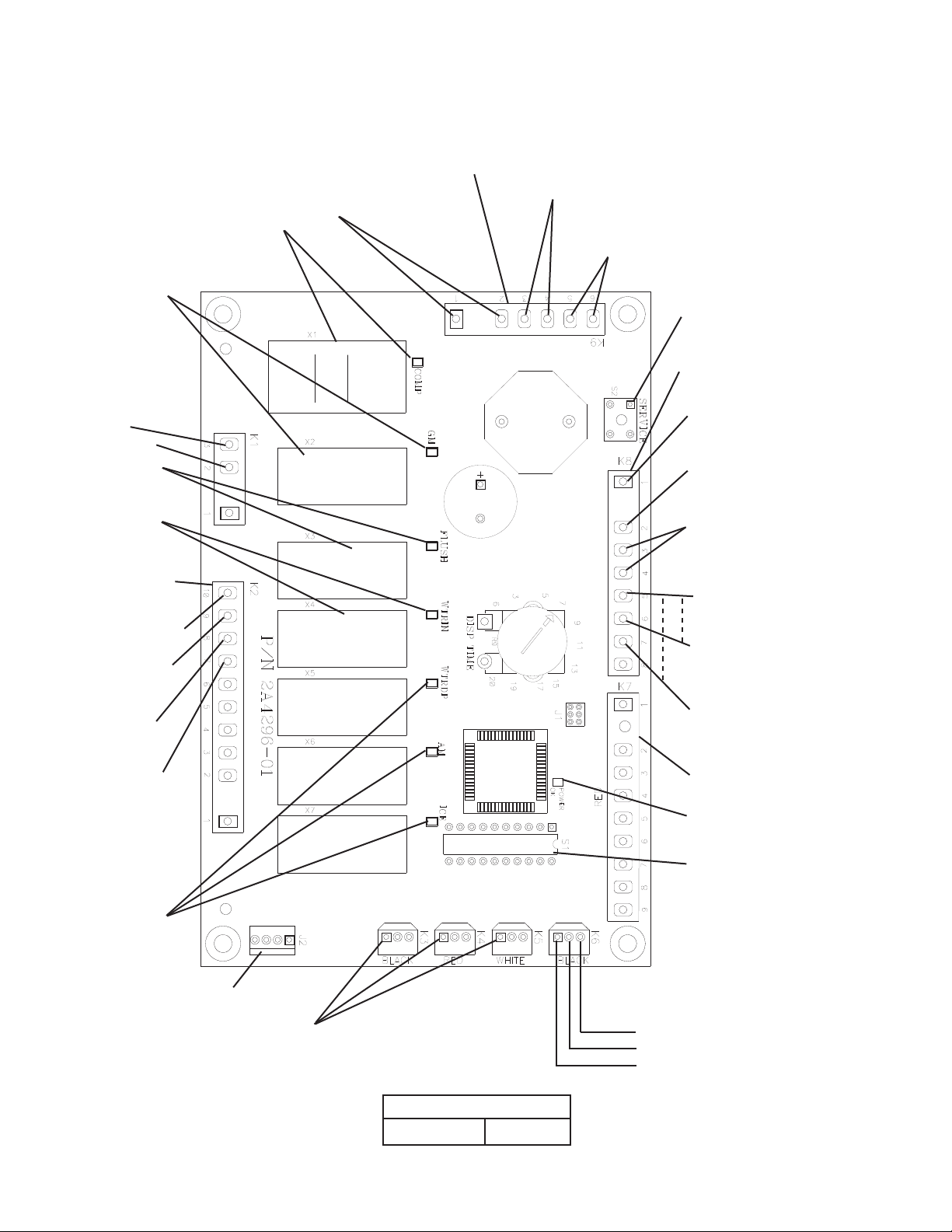
• K1 Connector
(115VAC)
GM, CCR/GMPR, EH,
FM, FMR #3
115VAC Input #2
Drain Valve
#10 (W/BU)
Control Transformer
24VAC Input
#1 (white/red)
Upper Float Switch
#6 (red) (5VDC)
Compressor Control Relay Circuit/Gear
Motor Protect Relay Circuit
#5 to #6 (white/orange)
High-Pressure Switch
#3 to #4 (yellow)
Control Switch
#1 to #2 (white/black)
• "POWER OK" LED
Control Transformer
24VAC Neutral
#2 (light blue)
Lower Float Switch
#7 (blue) (5VDC)
Float Switch-Common
#5 (black) (5VDC)
• S1 Dip Switch
• K8 Connector
(24VAC and 5VDC)
• K7 Connector-Open
• K2 Connector
(24VAC)
Fig. 3
5VDC common terminals
• K3 Connector-Open
• K4 Connector-Open
• K5 Connector-Open
Inlet Water Valve
#8 (O)
3 2 1
Control Board
Part Number
2A48054-01
(DRAIN)
• K6 Connector (20VDC)
Bin Control 1 (infrared sensor)
(dark blue)
(white, signal (common))
(brown (ground))
• J2 Connector-Open
Water Dispensing
Valve, Agitation
Motor, and Ice
Dispensing LEDs
(not used on
these models)
Control Transformer
24VAC Input
#7 (white/red)
Control Transfor mer
24VAC Input
#9 (white/red)
• S2 "SERVICE" Button
(Ice Purge Cycle Bypass)
Bin Control (2) (mechanical)
#3 & #4 (gray) (5VDC)
• "FLUSH" LED
(X3 Relay) (drain)
DV
• "WTRIN" LED
(X4 Relay)
WV
• "GM" LED
(X2 Relay)
GM
• "COMP" LED
(X1 Relay)
Comp, LLV, SLV
• K9 Connector (5VDC)
Control Board
30
D. Bin Control Check
1. Bin Control 1 (infrared sensor) Check
IMPORTANT
Make sure CB S1 dip switch 7 is in the "ON" position. This allows the control board
to monitor BC1 (infrared sensor) along with BC2 (mechanical) backup bin control.
1) Turn off the power supply.
2) Remove the front panel, top panel, and control box cover.
3) Conrm that CB S1 dip switch 1, 2, 3 are in the proper position for your application.
See "III.B.2. BC1 (Infrared Sensor) Shutdown Delay (S1 dip switch 1, 2, 3)."
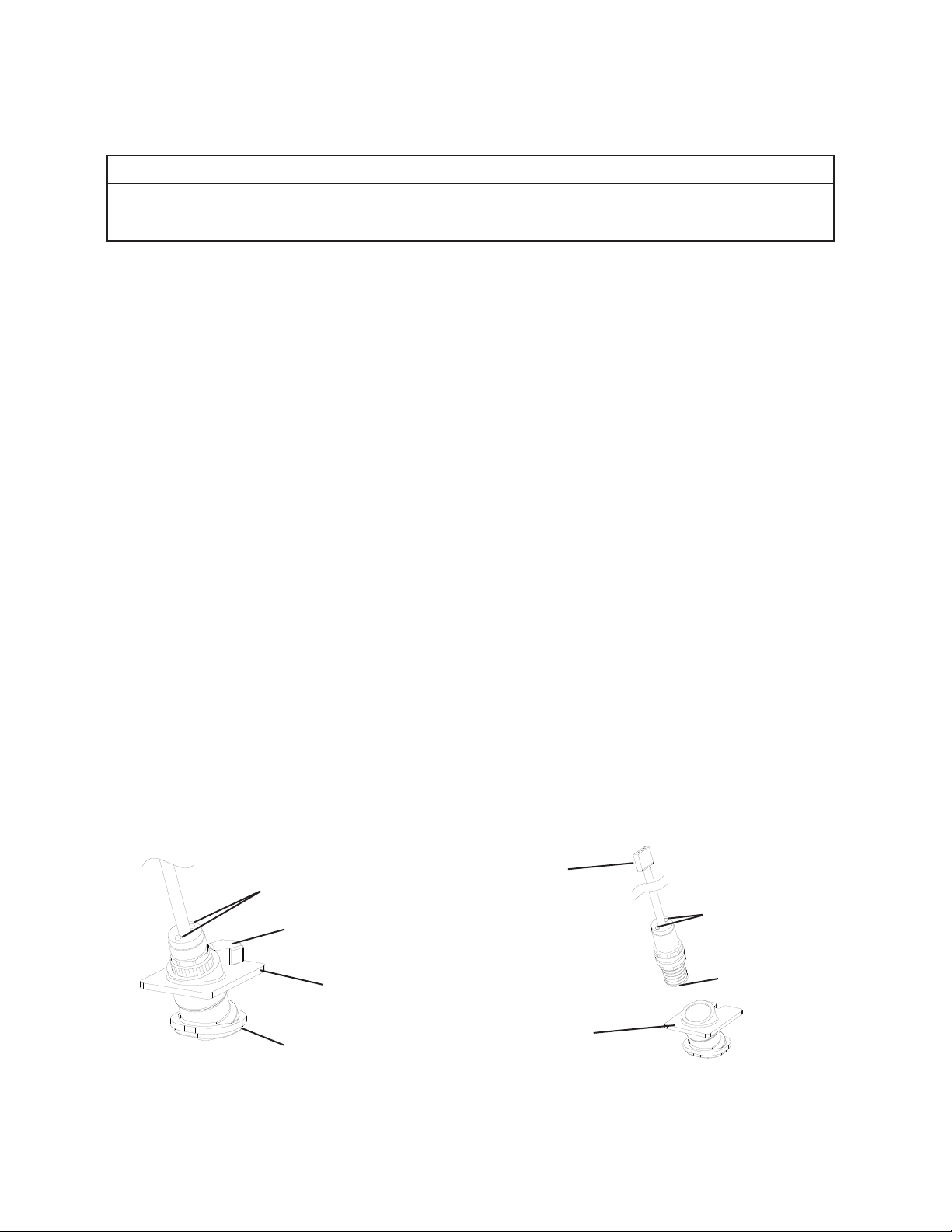
4) Conrm that BC1 is connected to CB K6 connector. Wipe down BC1 lens with a warm,
clean, damp cloth. If the bottom of the icemaker is not accessible in your application,
remove the thumbscrew securing the BC1 housing, then remove the housing from the
base. See Fig. 4.
5) Move the control switch to the "ICE" position, then move the power switch to the "ON"
position.
6) Turn on the power supply to start the automatic icemaking process. Check that BC1
green LED is on. The BC1 green LED conrms 20VDC power from CB to BC1 and
remains on constantly. Diagnosis: If the BC1 green LED is not on, conrm 20VDC
at CB K6 #1 (DBU) to CB K6 #3 (BR). If 20VDC is present and the BC1 green LED is
off, replace BC1. If not, see step "3) BC1 (infrared sensor) Power Supply," under "II.C.
Control Board Check.
7) Make sure CB "GM" LED is on. There is a delay of at least 30 sec. before the "GM" LED
turns on after power-up. After CB "GM" LED turns on, press CB "SERVICE" button to
bypass the 5-min. ice purge cycle. WARNING! Risk of electric shock. Care should be
taken not to touch live terminals.
Fig. 4
Housing
Connector
(20VDC from
K6 connector on
control board)
LEDs
Lens
Housing
Lens
LEDs
BC1 (infrared sensor)
Thumbscrew

31
8) CB "GM" and "COMP" LEDs are on. Use an object to cover BC1 lens at the bottom of
the icemaker. If the bottom of the icemaker is not accessible in your application, remove
the thumbscrew securing BC1 housing, remove the housing from the base, then cover
BC1 lens. See Fig. 4. The yellow LED on BC1 turns on (ashing or steady). The yellow
LED ashes when ice is at the outer limit of its range and turns steady as ice nears.
After the yellow LED turns on (ashing or steady), BC1 shutdown delay timer starts.
See "III.B.2. BC1 (Infrared Sensor) Shutdown Delay (S1 dip switch 1, 2, 3)." Comp
(LLV/SLV on MLH model) should de-energize immediately after the shutdown delay
timer terminates. 5 min. later, GM and FM/FMR should de-energize.
Diagnosis: If BC1 yellow LED is not on after covering the lens, replace BC1. If the
appliance remains on after BC1 shutdown delay timer terminates and the 5-min. ice
purge timer terminates, replace CB. If BC1 fails to shut down the icemaker and the level
of ice activates BC2, the icemaker shuts down and a 9-beep alarm sounds. To reset,
move the power switch to the "OFF" position, and then back to the "ON" position.
9) Remove the object covering the lens. If you removed BC1 housing from the base,
replace it in its correct position, and secure it with the thumbscrew.
10) Move the power switch to the "OFF" position. Turn off the power supply, then proceed
to "II.D.2. Bin Control 2 (mechanical stand-alone or backup) Check."
Legend: BC1–bin control 1 (infrared sensor); BC2–bin control 2 (mechanical stand-alone
or backup); CB–control board; Comp–compressor; FM–fan motor; FMR–fan
motor-remote; GM–gear motor; LLV–liquid line valve;
SLV –suction line valve
32
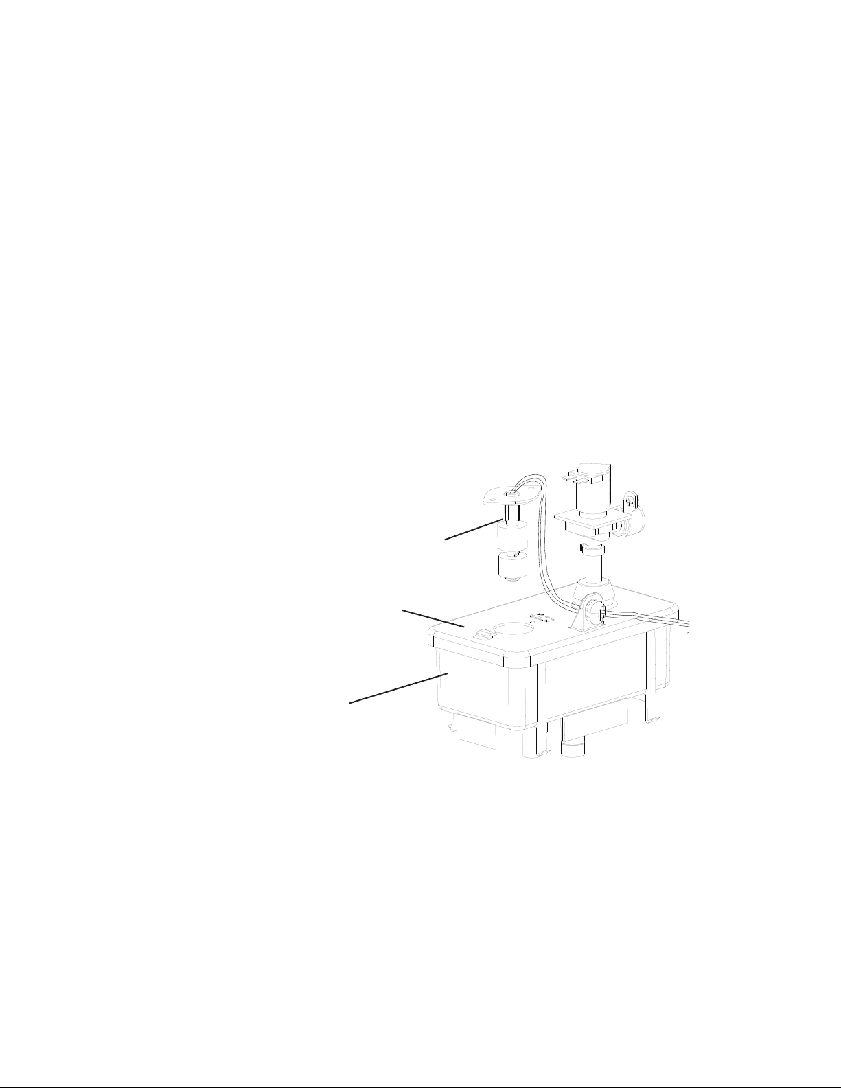
Fig. 5
Chute Assembly
Actuator Paddle
Spout
Strap
Proximity Switch
Strap
Model Shown: F-1501MRH-C
2. Bin Control (2) (mechanical stand-alone or backup) Check
When the actuator paddle is not engaged BC(2) is closed and the icemaker produces
ice.
a) Bin Control (Mechanical Stand-Alone): With CB S1 dip switch 7 placed in the
"OFF" position, BC is used as a stand-alone bin control. The stand-alone application
should only be used in standard ice storage bin applications.
WARNING! Do not place CB S1 dip switch 7 in the "OFF" position on
dispenser unit applications. This could lead to icemaker movement or ice
overow. When ice lls the chute and engages the actuator paddle, BC opens and
CB shuts down the icemaker within 10 sec.
b) Bin Control 2 (Mechanical Backup): With CB S1 dip switch 7 placed in the
"ON" position, BC2 is used as a backup bin control safety. When ice lls the chute
and engages the actuator paddle, BC2 opens and CB shuts down the icemaker
immediately and sounds a 9-beep alarm.
1) Make sure the power supply is off. Remove the front panel, top panel, and control box
cover.
2) Remove the strap connecting the spout to the chute assembly. See Fig. 5. Pull up the
chute assembly slightly so that you can access the actuator paddle located in the top of
the chute.
3) Move the power switch to the "ON" position.
4) Turn on the power supply to start the automatic icemaking process.
5) Make sure CB "GM" LED is on. There is a delay of at least 30 sec. before "GM" LED
turns on after power-up. After "GM" LED turns on, press CB "SERVICE" button to
bypass the 5-min. compressor delay. WARNING! Risk of electric shock. Care should
be taken not to touch live terminals. The "COMP" LED turns on.

33
6) Press the actuator paddle located in the top of the chute.
CB S1 dip switch 7 in the "ON" position: Comp (LLV and SLV on MLH model) and
GM de-energize and CB sounds a 9-beep alarm.
CB S1 dip switch 7 in the "OFF" position: Comp (LLV and SLV on MLH model) and
GM de-energize within 10 sec.
Diagnosis: If BC(2) does not open or the icemaker continues to make ice, check
that the actuator paddle is engaged. Check for continuity across BC(2) wires. If BC(2)
contacts are found open and the icemaker continues to make ice, replace CB. If BC2 is
closed with the actuator paddle engaged, replace BC(2).
7) Move the power switch to the "OFF" position and turn off the power supply.
8) Replace the chute assembly and strap in their correct positions.
9) Move the power switch to the "ON" position.
10) Replace the control box cover, top panel, and front panel in their correct positions.
11) Turn on the power supply to start the automatic icemaking process.
Legend: BC1–bin control 1 (infrared sensor); BC(2)–bin control (2) (mechanical stand-alone
or backup); CB–control board; Comp–compressor; FM–fan motor; FMR–fan
motor-remote; GM–gear motor; LLV–liquid line valve; SLV–suction line valve
34
Red (R)
(upper oat switch)
Black (BK)
(common)
Blue (BU) (lower
oat switch)
Upper Float (blue)
Magnet (towards top)
Magnet (towards top)
Lower Float (white)
Plastic Retainer Clip
Spring Retainer Clip
Fig. 6
E. Float Switch Check and Cleaning
1. Float Switch Check
A dual oat switch is used to determine that there is sufficient water in the reservoir
during ll and rell. CB monitors UFS to de-energize WV when UFS closes during ll and
rell. CB monitors LFS to energize WV when LFS opens during the freeze cycle (rell).
CB monitors the time between LFS opening and UFS closing (90-sec. low water safety).
CB also monitors the time between UFS closing and LFS opening (30-min. freeze timer).
No adjustment is required.
1) Remove the front panel and move the power switch to the "OFF" position. Move the
control switch to the "DRAIN" position.
2) Move the power switch to the "ON" position.
3) Allow the water to drain from the reservoir, then move the power switch to the "OFF"
position and the control switch to the "ICE" position.
4) Disconnect the molex plug from the control box and check continuity across FS wires.
(BK) to (R) for UFS and (BK) to (BU) for LFS. See Fig.6. With the water reservoir
empty, FS switches are open. If open, continue to step 5. If closed, follow the steps in
"II.E.2. Float Switch Cleaning." After cleaning the oats, check them again. Replace if
necessary.
5) Reconnect the molex plug on the control box.
6) Move the power switch to the "ON" position and let the water reservoir ll.
7) Once the reservoir is full and GM starts, move the power switch to the "OFF" position.
8) Disconnect the molex plug from the control box and check continuity across FS wires.
(BK) to (R) for UFS and (BK) to (BU) for LFS. They should be closed. Clean or replace if
necessary.
35
2. Float Switch Cleaning
Depending on local water conditions, scale may build up on FS. Scale on FS can cause
the oats to stick. In this case, FS should be cleaned and checked.
1) Turn off the power supply.
2) Remove the oat switch assembly from the reservoir cover. See Fig. 7.
3) Wipe down FS assembly with a mixture of 1 part Hoshizaki "Scale Away" and 25 parts
warm water.
4) While not necessary, the oats can be removed from the shaft during cleaning. If you
remove them, note that the blue oat is on top. The oats must be installed with the
magnets inside them towards the top of the switch. See Fig. 6. Installing the oats
upside down will affect the timing of FS operation.
5) Rinse FS assembly thoroughly with clean water and replace in its original position.
Legend: CB–control board; FS–oat switch; GM–gear motor; LFS–lower oat switch;
UFS–upper oat switch; WV–inlet water valve
Reservoir
Reservoir Cover
Float Switch Assembly
Fig. 7
36
F. Diagnostic Tables
Before consulting the diagnostic charts, check for correct installation, proper voltage per
appliance nameplate, and adequate water supply. Check control board using the steps in
"II.C. Control Board Check."
1. No Ice Production
No Ice Production - Possible Cause
Startup
1. Power Supply a) Off, blown fuse, or tripped breaker.
b) Loose connection.
c) Bad contacts.
d) Not within specications.
2. Water Supply a) Water supply off or pressure too low.
3. Power Switch
(Control Box)
a) "OFF" position.
b) Bad contacts.
4. Control Transformer a) Coil winding opened.
5. Fuse (Control Box) a) Blown.
6. BC1 (Infrared Sensor) a) No power or defective.
7. BC(2) (Mechanical
Stand-Alone or
Backup)
a) Tripped with bin lled with ice.
(9-beep alarm when used in conjunction with BC1 (infrared sensor)
b) Switch stuck open.
c) Actuator paddle does not move freely.
8. High-Pressure Switch a) Bad Contacts.
b) Dirty air lter or condenser.
c) Ambient or condenser water temperature too warm.
d) Refrigerant overcharged.
e) Fan not operating (except water-cooled model).
f) Refrigerant line or component restricted.
g) Condenser water pressure too low or off (water-cooled model).
h) Water regulating valve set too high (water-cooled model).
9. Control Switch a) "DRAIN" position. 2-beep alarm if in "DRAIN" position for more than 15 min.
b) Bad contacts.
Fill Cycle
1. Control Board a) No Power to inlet water valve.
b) No power to oat switch or not reading oat switch condition.
2. Inlet Water Valve a) Screen or orice clogged.
b) Coil winding opened.
3. Float Switch a) Float does not move freely.
b) Defective.
4. Drain Water Valve a) Valve seat clogged and water leaking.
5. Hoses a) Disconnected.

37
Ice Purge Cycle
1. Control Board a) No power to gear motor.
b) No power to compressor control relay.
2. Gear Motor a) Blown fuse.
b) Internal protector open.
c) Defective.
Freeze Cycle
1. Compressor Control
Relay
a) No voltage from gear motor.
b) Defective.
2. Control Board a) Defective.
3. Start Relay a) Bad contacts.
b) Coil winding opened.
c) Loose connections.
4. Capacitor (start or run) a) Defective, weak.
5. Power Supply a) Not within specications.
6. Refrigerant Line a) Gas leaks.
b) Refrigerant line or component restricted.
7. Thermostatic
Expansion Valve
(TXV) (not adjustable)
a) Defective.
8. Compressor a) Defective.
9. Liquid Line Valve
(MLH models)
a) Defective.
10. Suction Line Valve
(MLH models)
a) Defective.
11. Fan Motor
(if applicable)
a) Compressor Control Relay/Magnetic Contactor defective.
b) Defective capacitor.
c) Defective.
d) Control board defective.
12. Evaporator a) Dirty.
b) Damaged or defective.
13. Headmaster (C.P.R.)
(remote air-cooled
model)
a) Not operating properly and liquid line temperature too warm.
14. Water Supply Line
(water-cooled model)
a) Condenser water pressure too low or off and high pressure control opens and
closes frequently.
15. Water Regulating
Valve
(water-cooled model)
a) Set too high.
16. Magnetic Contactor
(if applicable)
a) Defective.
1 7. Drain Valve a) Dirty, leaking by.
b) Defective.
18. Water System a) Water leaks.
38
Rell
1. Float Switch a) Dirty/sticking.
b) Defective.
2. Inlet Water Valve a) Clogged or defective.
3. Water Supply a) Off.
4. Control Board a) No power to oat switch or not reading oat switch condition.
b) No power to inlet water valve.
Shutdown
1. BC1 (Infrared Sensor)
See "II.D. Bin Control
Check."
a) Dirty lens.
b) Defective.
2. BC(2) (Mechanical
Stand-Alone or
Backup)
See "II.D. Bin Control
Check."
a) Actuator paddle does not move freely.
b) Defective.
3. Control Board a) Control board dip switches set incorrectly.
b) In alarm.
c) Defective.
Drain Cycle
1. Drain Valve a) Screen or orice clogged.
b) Defective.
2. Control Board a) Defective.

39
III. Controls and Adjustments
A. Control Board
• A Hoshizaki exclusive control board is employed.
• All models are pretested and factory adjusted.
• For a control board check procedure, see "II.C. Control Board Check."
NOTICE
• Fragile, handle very carefully.
• The control board contains integrated circuits, which are susceptible to failure
due to static discharge. It is especially important to touch the metal part of the
icemaker when handling or replacing the control board.
• Do not touch the electronic devices on the control board or the back of the control
board.
• Do not change wiring and connections. Do not misconnect terminals.
• Do not short out power supply to test for voltage.
• Always replace the whole control board assembly if it goes bad.
40
1. Control Board Layout
• K1 Connector
(115VAC)
GM, CCR/GMPR, EH,
FM, FMR #3
115VAC Input #2
Drain Valve #10
Control Transformer
24VAC Input
#1 (white/red)
Upper Float Switch
#6 (red) (5VDC)
Compressor Control Relay Circuit/Gear
Motor Protect Relay Circuit
#5 to #6 (white/orange) (5VDC)
High-Pressure Switch
#3 to #4 (yellow) (5VDC)
Control Switch
#1 to #2 (white/black) (5VDC)
• "POWER OK" LED
Control Transformer
24VAC Neutral
#2 (light blue)
Lower Float Switch
#7 (blue) (5VDC)
Float Switch
#5 (black) (5VDC)
• S1 Dip Switch
• K8 Connector
(24VAC and 5VDC)
• K7 Connector-Open
• K2 Connector
(24VAC)
5VDC common terminals
• K3 Connector-Open
• K4 Connector-Open
• K5 Connector-Open
Inlet Water
Valve #8
3 2 1
(DRAIN)
• K6 Connector (20VDC)
Bin Control 1 (infrared sensor)
(dark blue)
(white, signal (common))
(brown (ground))
• J2 Connector-Open
Water Dispensing
Valve, Agitation
Motor, and Ice
Dispensing LEDs
(not used on
these models)
Control Transformer
24VAC Input
#7 (white/red)
Control Transfor mer
24VAC Input
#9 (white/red)
• S2 "SERVICE" Button
(Ice Purge Cycle Bypass)
Bin Control (2) (mechanical)
#3 & #4 (gray) (5VDC)
• "FLUSH" LED
(X3 Relay) (drain)
DV
• "WTRIN" LED
(X4 Relay)
WV
• "GM" LED
(X2 Relay)
GM
• "COMP" LED
(X1 Relay)
Comp, LLV, SLV
• K9 Connector (5VDC)
Control Board
Part Number
2A8054-01
41
2. LED Lights and Audible Alarm Safeties
The "POWER OK" LED indicates proper control voltage and will remain on unless a
control voltage problem occurs. For further details, see "II.A. Sequence of Operation Flow
Chart."
Sequence Step LED
Energized
Components Min. Max.
Fill Cycle WTRIN WV - -
Ice Purge Cycle GM GM, FM/FMR 5 min. 5 min.
Freeze Cycle (with rell) GM, WTRIN* (rell),
COMP
GM, Comp,
FM/FMR, LLV,
SLV, WV* (rell)
- *On until UFS closes.
Alarm sounds after
90 sec.
Drain Cycle FLUSH (Drain) DV 2 sec. 10 min.
The built-in alarm safeties shut down the unit.
No. of Beeps
(every 5 sec.)
Type of Alarm Reset Options
1 Low Water Safety
UFS open > 90 sec. after WV energized.
Automatic reset once water supply is restored
and UFS closes.
2 Control Switch
In "DRAIN" position longer than 15 min..
Automatic reset once the control switch is
moved to the "ICE" position.
3 High-Pressure Switch
First and sec. activation in 1 hour.
Automatic reset once pressure drops below the
high pressure threshold and the high pressure
switch closes.
4 High-Pressure Switch
Third activation in 1 hour.
Call for service. To avoid possible catastrophic
failure, it is recommended to leave the
icemaker off until this alarm is resolved.
Manual reset. Turn power off and on again.
5 Freeze Timer
WV off > 30 min. since last WV activation.
Manual reset. Turn power off and on again.
6 Low Voltage
(92VAC±5% or less)
"POWER OK" LED turns off if voltage
protection operates.
The control voltage safeties automatically reset
when voltage is corrected.
7 High Voltage
(147VAC±5% or more)
8 Gear Motor
CCR contacts fail to close.
Manual reset. Turn power off and on again.
9 BC1 (infrared sensor) fails (CB S1 dip switch
7 on)
BC2 (mechanical backup) actuator paddle
engaged.
Manual reset. Turn power off and on again.
Legend: BC1–bin control (infrared sensor); BC2–bin control 2 (mechanical backup);
CB–control board; CCR–compressor control relay; Comp–compressor;
DV–drain valve; FM–fan motor; FMR–fan motor-remote; GM–gear motor;
LLV -liquid line valve (MLH model); SLV –suction line valve (MLH model);
UFS–upper oat switch; WV–inlet water valve
42
3. Ice Purge Cycle Bypass
To speed up the diagnostic process, the 5-min. ice purge cycle may be bypassed
by pressing the "SERVICE" button on the control board after the gear motor starts.
WARNING! Risk of electric shock. Care should be taken not to touch live terminals.
B. Controls and Adjustments
NOTICE
Dip switches are factory set. Failure to maintain factory settings may adversely
affect performance and warranty coverage. For more information, contact your
Hoshizaki Certied Service Representative.
1. Default Dip Switch Settings
The S1 dip switch settings are factory-set to the following positions:
a) Single Bin Control Models (BC Mech. Stand-Alone or BC2 Backup Only)
Dip Switch No. 1 2 3 4 5 6 7 8 9 10
F-1001M_H(-C) OFF OFF OFF OFF OFF OFF OFF OFF OFF OFF
F-1001M_J(-C) OFF OFF OFF OFF OFF OFF OFF OFF OFF OFF
b) Multiple Bin Control Models (BC1 Infrared Sensor and BC2 Backup)
Dip Switch No. 1 2 3 4 5 6 7 8 9 10
F-1501M_H(-C) ON OFF OFF OFF OFF OFF ON ON OFF OFF
F-2001M_H(3)(-C) ON OFF OFF OFF OFF OFF ON ON OFF OFF
FD-1001M_H-C ON OFF OFF OFF OFF OFF ON ON OFF OFF
FD-1001M_J-C ON OFF OFF OFF OFF OFF ON ON OFF OFF
c) Single Bin Control Models (BC1 Infrared Sensor Only)
Dip Switch No. 1 2 3 4 5 6 7 8 9 10
F-450MAJ(-C) ON OFF OFF OFF OFF OFF ON ON OFF OFF
F-801M_J(-C) ON OFF OFF OFF OFF OFF ON ON OFF OFF
F-1002M_J(-C) ON OFF OFF OFF OFF OFF ON ON OFF OFF
F-1501M_J(-C) ON OFF OFF OFF OFF OFF ON ON OFF OFF
F-2001M_J(-C) ON OFF OFF OFF OFF OFF ON ON OFF OFF
FD-650M_H-C ON OFF OFF OFF OFF OFF ON ON OFF OFF
FD-1002M_J-C ON OFF OFF OFF OFF OFF ON ON OFF OFF
Bin Control 1 (infrared sensor) Shutdown Delay
Continuous Dispensing Timer
(DCM models only, do not adjust on modular icemakers)
Drain Frequency Control
Bin Control Selector
Bin Control (BC or BC2) (mechanical stand-alone or backup) Shutdown Delay
Normally off (factory use)
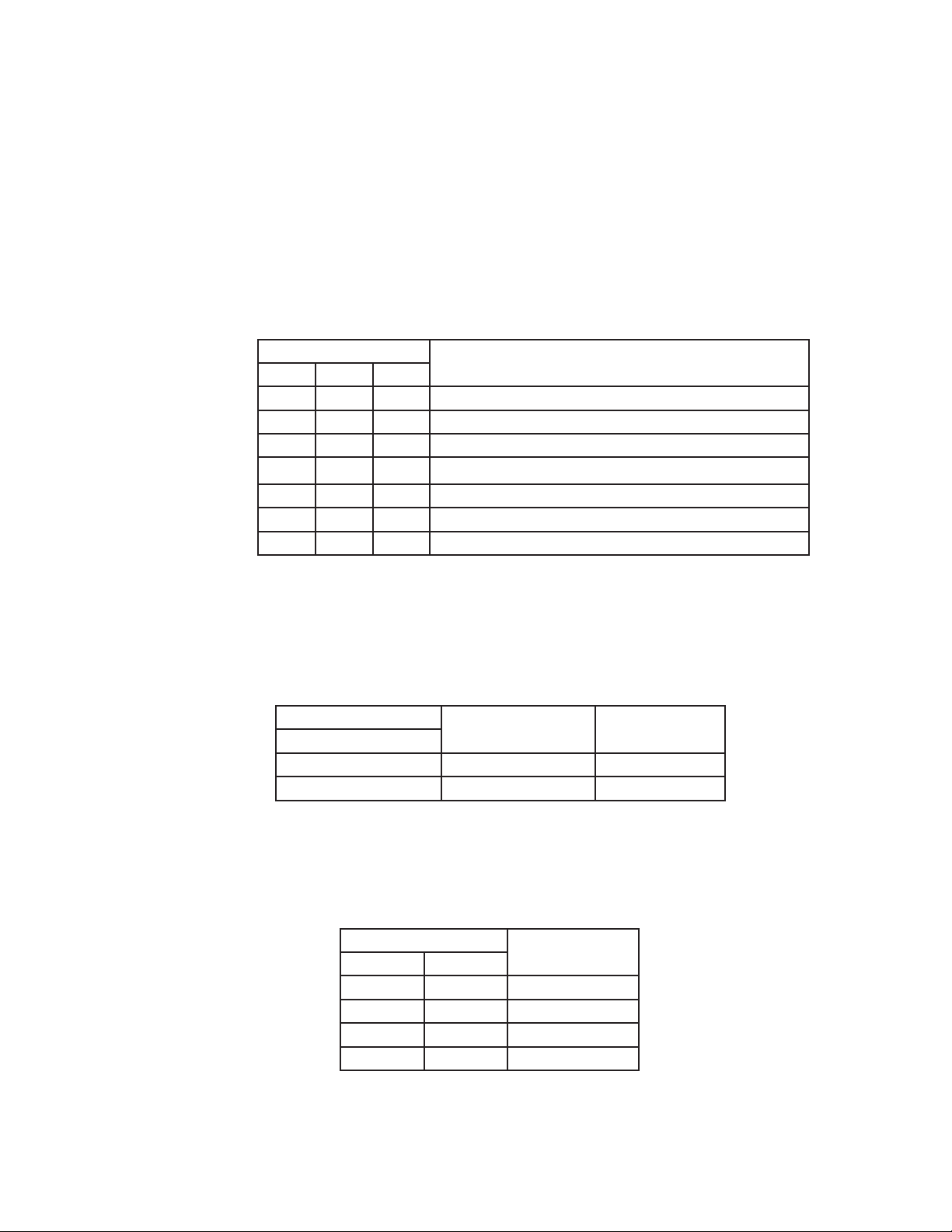
43
2. BC1 (Infrared Sensor) Shutdown Delay (S1 dip switch 1, 2, 3)
Infrared sensor shutdown delay is the delay between the infrared sensor detecting ice
(infrared sensor yellow LED ashing or steady) and the start of the shutdown sequence.
For dispenser unit applications, the ice level at shutoff may need to be adjusted
depending on the dispenser agitation or dispense method. Increasing the shutdown
delay setting allows for a higher level of ice in the bin before the icemaker shuts down.
For a typical dispenser unit application, a 100-sec. shutdown delay is recommended.
When used with a standard Hoshizaki ice storage bin, any shutdown delay setting is
acceptable. WARNING!Increasing the shutdown delay allows a higher level of ice
in the dispenser unit/ice storage bin before shutdown. This could lead to icemaker
movement or ice overow.
S1 Dip Switch Setting
Infrared Sensor Shutdown Delay
No. 1 No. 2 No. 3
OFF OFF OFF 0 Seconds
ON OFF OFF 100 Seconds (1.6 minutes) (Factory Default)
OFF ON OFF 1100 Seconds (18.3 minutes)
OFF OFF ON 1650 Seconds (27.5 minutes)
ON ON OFF 2200 Seconds (36.7 minutes)
OFF ON ON 0 Seconds
ON ON ON 0 Seconds
3. Drain Frequency Control (S1 dip switch 4)
This unit is factory set for optimum performance with the 1-in-1 drain cycle (S1 dip
switch 4 in the off position). This setting allows for removal of sediment from the
evaporator without interrupting the icemaking process. An optional 1-in-12 drain cycle is
available.
S1 Dip Switch Setting
Drain Timer Interval Drain Valve Open
No. 4
OFF (1-in-1) 1 Hour 2 Seconds
ON (1-in-12) 11 Hours 45 Minutes 10 Minutes
4. Continuous Dispensing Timer (S1 dip switch 5 & 6)
DCM models only. The dispense mode switch on DCMs must be in the "CONTINUOUS"
position for this setting to apply. The factory setting allows ice to be dispensed
continuously as long as the dispense solenoid is activated.
S1 Dip Switch Setting
Dispense Time
No. 5 No. 6
OFF OFF No Limit
ON OFF 20 Seconds
OFF ON 60 Seconds
ON ON No Limit
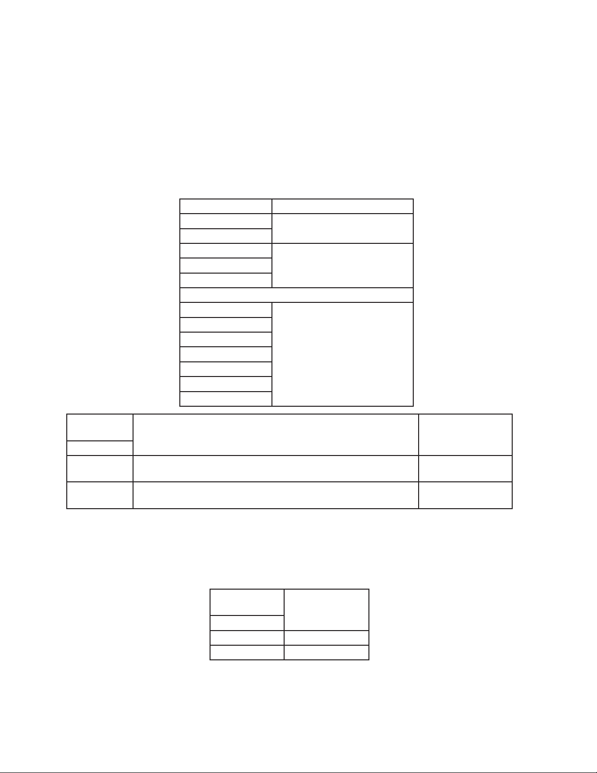
44
5. Bin Control Selector (S1 dip switch 7)
The bin control is factory set. No adjustment required. When used on a standard ice
storage bin, only the mechanical bin control should be used. The BC stand-alone or
BC2 backup on dual bin control units. The BC2 backup may be used instead of the
infrared sensor (BC1). When the mechanical bin control is used (S1dip switch 7 in the
off position), the gear motor delay after the upper oat switch closes is 5 sec. When the
infrared sensor (BC1) stand-alone or infrared sensor (BC1) with backup (BC2) is used
(S1 dip switch 7 in the on position), the gear motor delay after the upper oat switch
closes is 30 sec. WARNING! Do not place S1 dip switch 7 in the off position on
dispenser unit applications. This could lead to icemaker movement or ice overow.
Model Bin Control
F-1001M_H(-C)
BC (mechanical stand-alone)
F-1001M_J(-C)
F-1501M_H(-C)
BC1 (infrared sensor) with
BC2 (mechanical backup)
F-2001M_H(-C)
FD-1001M_H(-C)
F-450MAJ(-C)
BC1 (infrared sensor)
F-801M_J(-C)
F-1002M_J(-C)
F-1501M_J(-C)
F-2001M_J(-C)
FD-650M_H-C
FD-1002M_J-C
S1 Dip Switch
Setting
Bin Control Application Gear Motor Delay
No. 7
OFF
BC (mechanical stand-alone) (Standard Ice Storage Bins Only)
BC2 (mechanical backup only)
5 seconds
ON
BC1 (infrared sensor) Stand-Alone and
BC1 (infrared sensor) with BC2 (mechanical backup)
30 seconds
6. BC(2) (Mech. Stand-Alone or Backup (only)) Shutdown Delay (S1 dip switch 8)
Not available when S1 dip switch 7 is on. Factory set for normal operation. No adjustment
is required. The shutdown delay is the time between the mechanical bin control proximity
switch opening and the control board shutting off the icemaker.
S1 Dip Switch
Setting
Shutdown Delay
No. 8
OFF No Delay
ON 6 to 10 Seconds
7. Factory Use (S1 Dip Switch 9 & 10)
Factory set for optimum performance. Do not adjust.

45
C. Power Switch and Control Switch
The power switch and the control switch are used to control the icemaker. They are
located on the control box.
1. Power Switch
The power switch has 2 positions, "OFF" and "ON." When the power switch is in the
"OFF" position, no power is supplied to the components. When in the "ON" position,
power is supplied to the control transformer and control board. The control board then
supplies 5VDC to the control switch for unit operation.
2. Control Switch
The control switch has 2 positions, "ICE" and "DRAIN."
When the control switch is in the "ICE" position (open), icemaking begins.
When the control switch is in the "DRAIN" position (closed), the drain valve energizes.
a) ICE
When the control switch is in the "ICE" position, the control board reads an open
circuit through the control switch contacts and starts the icemaking process.
b) DRAIN
When the control switch is in the "DRAIN" position, the control board reads a closed
circuit through the control switch and the drain valve energizes.IV. Refrigeration Circuit
and Component Service Information
46
IV. Refrigeration Circuit and Component Service Information
WARNING
• This appliance should be diagnosed and repaired only by qualied service
personnel to reduce the risk of death, electric shock, serious injury, or re.
• Move the power switch to the "OFF" position and turn off the power supply. Place
the disconnect in the "OFF" position. Lockout/Tagout to prevent the power supply
from being turned back on inadvertently.
• CHOKING HAZARD: Ensure all components, fasteners, and thumbscrews are
securely in place after the appliance is serviced. Make sure that none have fallen
into the dispenser unit/ice storage bin.
• Make sure all food zones in the icemaker and dispenser unit/ice storage bin are
clean after service.
A. Refrigeration Circuit Service Information
WARNING
• Repairs requiring the refrigeration circuit to be opened must be performed by
properly trained and EPA-certied service personnel.
• Use an electronic leak detector or soap bubbles to check for leaks. Add a trace of
refrigerant to the system (if using an electronic leak detector), and then raise the
pressure using nitrogen gas (140 PSIG). Do not use R-404A as a mixture with
pressurized air for leak testing.
NOTICE
• Always recover the refrigerant and store it in an approved container. Do not
discharge the refrigerant into the atmosphere.
• Do not leave the system open for longer than 15 min. when replacing or servicing
parts. The Polyol Ester (POE) oils used in R-404A applications can absorb
moisture quickly. Therefore it is important to prevent moisture from entering the
system when replacing or servicing parts.
• Always install a new drier every time the sealed refrigeration system is opened.
Do not replace the drier until after all other repair or replacement has been made.
Install the new drier with the arrow on the drier in the direction of the refrigerant
ow.
• When brazing, protect the drier by using a wet cloth to prevent the drier from
overheating. Do not allow the drier to exceed 250°F (121°C).
1. Refrigerant Recovery
Using proper refrigerant practices, recover the refrigerant. Recover via the access valves.
Store the refrigerant in an approved container. Do not discharge the refrigerant into the
atmosphere.
47
2. Brazing
WARNING
• R-404A itself is not ammable at atmospheric pressure and temperatures up to
176°F (80°C).
• R-404A itself is not explosive or poisonous. However, when exposed to high
temperatures (open ames), R-404A can be decomposed to form hydrouoric
acid and carbonyl uoride both of which are hazardous.
• Do not use silver alloy or copper alloy containing arsenic.
1) Braze all ttings while purging with nitrogen gas owing at a pressure of 3 to 4 PSIG.
NOTICE
• Always install a new drier every time the sealed refrigeration system is opened.
• Do not replace the drier until after all other repair or replacement has been made.
Install the new drier with the arrow on the drier in the direction of the refrigerant
ow.
• When brazing, protect the drier by using a wet cloth to prevent the drier from
overheating. Do not allow the drier to exceed 250°F (121°C).
2) Use an electronic leak detector or soap bubbles to check for leaks. Add a trace of
refrigerant to the system (if using an electronic leak detector), and then raise the
pressure using nitrogen gas (140 PSIG). Do not use R-404A as a mixture with
pressurized air for leak testing.
3. Evacuation and Recharge (R-404A)
1) Attach a vacuum pump to the system. Be sure to connect the charging hoses to both
high and low-side refrigerant access valves.
IMPORTANT
The vacuum level and vacuum pump may be the same as those for current
refrigerants. However, the rubber hose and gauge manifold to be used for
evacuation and refrigerant charge should be exclusively for POE oils.
2) Turn on the vacuum pump, then open the gauge manifold valves. Never allow the oil in
the vacuum pump to ow backwards.
3) Allow the vacuum pump to pull down to a 29.9" Hg vacuum. Evacuating period depends
on pump capacity.
4) Close the low-side valve and high-side valve on the gauge manifold.
5) Disconnect the gauge manifold hose from the vacuum pump and attach it to a
refrigerant service cylinder. Remember to loosen the connection and purge the air
from the hose. For the required refrigerant charge, see the nameplate. Hoshizaki
recommends only virgin refrigerant or reclaimed refrigerant which meets ARI Standard
700 (latest edition) be used.

48
6) A liquid charge is required when charging an R-404A system (to prevent fractionation).
Place the service cylinder on the scales; if the service cylinder is not equipped with
a dip tube, invert the service cylinder, then place it on the scales. Open the high-side
valve on the gauge manifold.
7) Allow the system to charge with liquid until the proper charge weight is met.
8) If necessary, add any remaining charge to the system through the low-side.
NOTICE!To prevent compressor damage, use a throttling valve or liquid
dispensing device to add the remaining liquid charge through the low-side
refrigerant access valve with the icemaker running.
9) Close the high and low-side gauge manifold valves, then disconnect the gauge manifold
hoses.
10) Cap the refrigerant access valves to prevent a possible leak.
49
B. Component Service Information
NOTICE
• When replacing a component listed below, see the notes to help ensure proper
operation.
• When replacing evaporator assembly and water circuit components, make sure
there are no water leaks after the repair is complete.
• Seal bolts must be replaced once removed because seal material is one-time use
only. If new seal bolts do not have preapplied threadlocker, apply Loctite243 or
equivalent threadlocker to seal bolt threads. Tighten to the torque values listed
below.
Torque for F-1001 and Smaller: 11.1 ft-lb/15 N·m
Torque for F-1500 and Larger: 25.8 ft-lb/35 N·m Tighten 2 times. Allow at least
5sec. in between each tightening.
Component Notes
Compressor • Install a new drier, start capacitor, and start relay.
Upper and Lower Bear-
ings
• Inspect the upper bearing for wear. See "IV.B.1. Upper Bearing Wear Check."
Replace if necessary.
• When replacing the upper bearing it is advised to also change the lower bearing
at the same time.
Evaporator • Install a new drier.
• Inspect the mechanical seal and O-ring prior to installing the new evaporator. If
worn, cracked, or scratched, the mechanical seal should also be replaced.
Gear Motor • Install a new gear motor capacitor.
Evaporator Pressure
Regulator (EPR Valve)
MLH models use only with R-404A.
R-404A EPR setting : 31 PSIG.
MLJ models use with only R-404A, R-407A, or R-407F.
R-404A EPR setting: 31 PSIG.
R-407A EPR setting: 22 PSIG.
R-407F EPR setting: 23 PSIG.
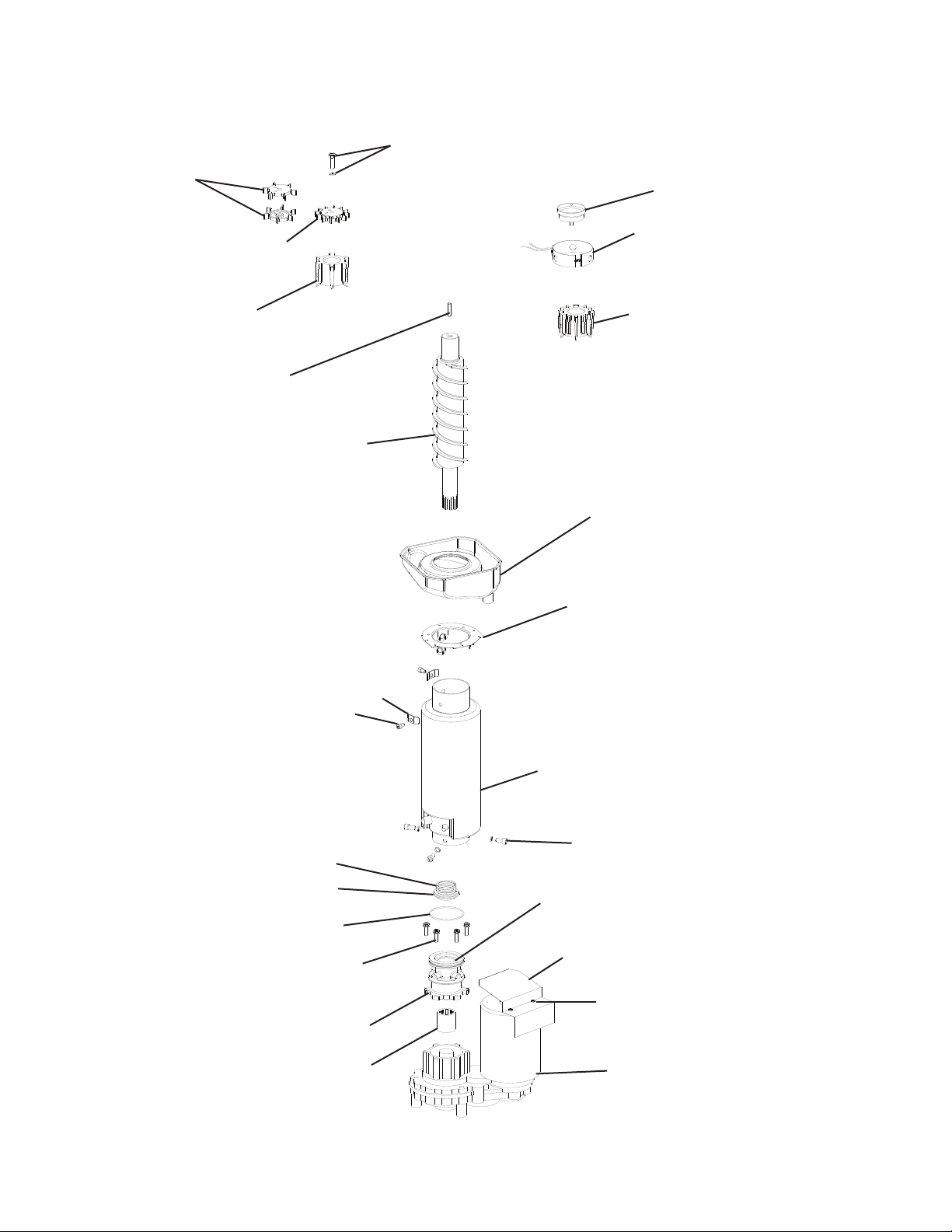
50
Fig. 8
Cutter Bolt and Washer (aker
models )
Flaker Extruding Head-
Upper Bearing
Evaporator
Socket Head Cap Screw
and Split Lock Washer
Seal Bolt
Lower Housing
Gear Motor
Spline Coupling
O-Ring
Mechanical Seal
Spring Retainer
Auger
Evaporator Heater
(-C models)
Hex Bolt and Washer
Cutter Pin
(Flaker models only)
Evaporator Assembly
Cubelet Extruding
Head-Upper Bearing
Flaker Cutter
(F-1501 and
(F-2001 models)
Flaker Cutter
F-1001models
Cubelet Cutter
Drip Pan
Flange
Gear Motor Barrier
Truss Head Screw
w/Rubber Washer
Lower Bearing
(pressed into lower housing)
Washer
(if applicable)
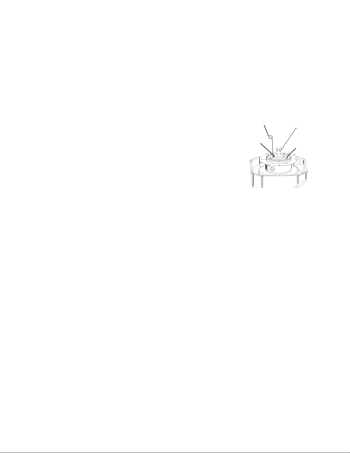
51
1. Upper Bearing Wear Check
To ensure that the bearing inside the extruding head does not exceed the wear tolerance
of .02", follow the instructions below.
1) Remove the front panel. Move the power switch to the "OFF" position, then turn off the
power supply.
2) Remove the top and side panels.
3) Remove the strap connecting the spout to the chute assembly, then remove the spout.
4) Remove the bolt (if applicable) or cutter from the auger and lift off the cutter and washer
(if applicable).
5) Replace the bolt in the auger (if applicable). See Fig. 9.
Move the auger towards you and then try to insert a .02"
round stock or pin gauge in between the back side of the
auger shaft and the bearing surface. Check several locations
around the auger shaft. If the gauge goes between the shaft
and the bearing at any point or if the bearing is scratched or
cracked, both the top bearing in the extruding head and the
lower bearing in the housing should be replaced. Instructions
for removing the extruding head and housing are located
later in this procedure.
Note: Replacing the bearing requires a bearing press adaptor. If one is not available,
replace the whole extruding head and housing.
6) Replace the washer (if applicable), cutter, and cutter bolt (if applicable).
7) Replace the spout.
8) Replace the top and side panels in their correct positions.
9) Move the power switch to the "ON" position, then turn on the power supply.
10) Replace the front panel in its correct position.
2. Removal and Replacement of Cutter
1) Remove the front panel. Move the power switch to the "OFF" position, then turn off the
power supply.
2) Remove the top and side panels.
3) Remove the strap connecting the spout to the chute assembly, then remove the spout.
4) Remove the bolt (if applicable) or cutter and lift off the cutter.
5) Install the new cutter. Replace the bolt (if applicable).
6) Replace the spout.
7) Replace the top and side panels in their correct position.
8) Move the power switch to the "ON" position, then turn on the power supply.
9) Replace the front panel in its correct position.
.02" Round Stock
or Pin Gauge
Extruding
Head
Auger
Fig. 9
Bolt (if applicable)

52
IMPORTANT! Seal Bolt Removal and Installation Instructions: Seal bolts must be
replaced once removed because seal material is one-time use only. If new seal bolts do
not have preapplied threadlocker, apply Loctite 243 or equivalent threadlocker to seal bolt
threads.
• Torque for F-1002 and Smaller: 11.1 ft-lb/15 N·m
• Torque for F-1501 and Larger: 25.8 ft-lb/35 N·m Tighten 2 times. Allow at least 5 sec. in
between each tightening.
3. Removal and Replacement of Extruding Head
1) Drain the water from the evaporator.
a) Remove the front panel, then move the power switch to the "OFF" position.
b) Move the control switch to the "DRAIN" position.
c) Move the power switch to the "ON" position and allow the water to drain from the
evaporator.
d) Move the power switch to the "OFF" position, then turn off the power supply.
2) Remove the top and side panels.
3) Remove the strap connecting the spout to the chute assembly, then remove the spout.
4) Remove the cutter bolt (if applicable) or cutter and lift off the cutter and washer (if
applicable).
5) Remove the seal bolts from the extruding head and lift off the extruding head.
6) Place the new extruding head in place and tighten down with new seal bolts.
See "Seal Bolt Removal and Installation Instructions" above.
7) Replace the washer (if applicable), cutter, cutter bolt (if applicable), and spout.
8) Replace the top and side panels in their correct positions.
9) Move the control switch to the "ICE" position.
10) Move the power switch to the "ON" position, then turn on the power supply.
11) Replace the front panel in its correct position.
4. Removal and Replacement of Auger
1) Drain the water from the evaporator.
a) Remove the front panel, then move the power switch to the "OFF" position.
b) Move the control switch to the "DRAIN" position.
c) Move the power switch to the "ON" position and allow the water to drain from the
evaporator.
d) Move the power switch to the "OFF" position, then turn off the power supply.
2) Remove the top and side panels.
3) Remove the strap connecting the spout to the chute assembly, then remove the spout.
4) Remove the extruding head seal bolts. Using the cutter, lift out the auger assembly.
5) Remove the cutter bolt (if applicable), cutter, washer (if applicable), and dowel pin (if
applicable). Remove the extruding head from the auger and place on the new auger.
6) Install the new auger.

53
7) Replace the removed parts in the reverse order of which they were removed.
Note: Be sure to use new seal bolts. See "Seal Bolt Removal and Installation
Instructions" above.
8) Replace the top and side panels in their correct positions.
9) Move the control switch to the "ICE" position.
10) Move the power switch to the "ON" position, then turn on the power supply.
11) Replace the front panel in its correct position.
5. Removal and Replacement of Evaporator
IMPORTANT
Always install a new drier every time the sealed refrigeration system is opened. Do
not replace the drier until after all other repair or replacement has been made.
1) Drain the water from the evaporator.
a) Remove the front panel, then move the power switch to the "OFF" position.
b) Move the control switch to the "DRAIN" position.
c) Move the power switch to the "ON" position and allow the water to drain from the
evaporator.
d) Move the power switch to the "OFF" position, then turn off the power supply.
2) Remove the top and side panels.
3) Recover the refrigerant and store it in an approved container.
4) Remove the strap connecting the spout to the chute assembly, then remove the spout.
5) Disconnect the water hoses.
6) Remove the extruding head seal bolts. Using the cutter, lift out the auger assembly.
7) Remove the insulation and the expansion valve bulb on the suction line.
8) Disconnect the inlet and outlet tubing.
9) Remove the socket head cap screws and split lock washers securing the evaporator to
the lower housing.
10) Lift off the evaporator.
11) Inspect the mechanical seal and O-ring prior to installing the new evaporator. The
mechanical seal consists of two parts. One moves along with the auger, and the other
is xed on the lower housing. If the contact surfaces of these two parts are worn,
cracked, or scratched, the mechanical seal may cause water leaks and should be
replaced. Instructions for removing the mechanical seal and lower housing are located
later in this procedure.
12) Make sure the lower mechanical seal is in place, then place the evaporator in position.
Secure the evaporator to the lower housing using the socket head cap screws and split
lock washers.
13) Remove the drier, then place the new drier in position.
14) Braze all ttings while purging with nitrogen gas owing at a pressure of 3 to 4 PSIG.

54
15) Use an electronic leak detector or soap bubbles to check for leaks. Add a trace of
refrigerant to the system (if using an electronic leak detector), and then raise the
pressure using nitrogen gas (140 PSIG). Do not use R-404A as a mixture with
pressurized air for leak testing.
16) Evacuate the system, and charge it with refrigerant. For air-cooled and water-cooled
models, see the nameplate for the required refrigerant charge. For remote models, see
the rating label inside the icemaker. Hoshizaki recommends only virgin refrigerant or
reclaimed refrigerant which meets AHRI Standard 700 (latest edition) be used.
17) Replace the removed parts in the reverse order of which they were removed.
Note: Be sure to use new seal bolts. See "Seal Bolt Removal and Installation
Instructions" earlier in this section.
18) Replace the top and side panels in their correct positions.
19) Move the control switch to the "ICE" position.
20) Move the power switch to the "ON" position, then turn on the power supply.
21) Replace the front panel in its correct position.
6. Removal and Replacement of Mechanical Seal and Lower Housing
6a. Mechanical Seal
1) Drain the water from the evaporator.
a) Remove the front panel, then move the power switch to the "OFF" position.
b) Move the control switch to the "DRAIN" position.
c) Move the power switch to the "ON" position and allow the water to drain from the
evaporator.
d) Move the power switch to the "OFF" position, then turn off the power supply.
2) Remove the top and side panels.
3) Remove the strap connecting the spout to the chute assembly, then remove the spout.
4) Remove the extruding head seal bolts. Using the cutter, lift out the auger assembly.
5) The mechanical seal consists of two parts. One moves along with the auger, and the
other is xed on the lower housing. If the contact surfaces of these two parts are worn,
cracked, or scratched, the mechanical seal may cause water leaks and should be
replaced.
6) Remove the socket head cap screws and split lock washers securing the evaporator to
the lower bearing housing.
7) Raise the evaporator up to access the lower housing.
8) Remove the O-ring and mechanical seal from the housing. If only replacing the
mechanical seal, proceed to step 11.
NOTICE
To help prevent water leaks, be careful not to damage the surfaces of the O-ring or
mechanical seal.

55
6b. Lower Housing
9) Remove the hex bolts w/washers securing the lower housing to the gear motor and
remove the lower housing from the gear motor. If inspection of the upper bearing inside
the extruding head (see "IV.B.1. Upper Bearing Wear Check") indicates that it is out of
tolerance, replace both it and the bearing inside the lower housing.
Note: Replacing the bearing requires a bearing press adaptor. If one is not available,
replace the whole extruding head and lower housing.
10) Mount the lower housing on the gear motor.
11) Install the O-ring and lower part of the mechanical seal on the lower housing.
12) Make sure the lower mechanical seal is in place, then place the evaporator in position.
Secure the evaporator to the lower housing using the socket head cap screws and split
lock washers.
13) Install the auger assembly with the upper part of the mechanical seal attached.
14) Replace the removed parts in the reverse order of which they were removed.
Note: Be sure to use new seal bolts. See "Seal Bolt Removal and Installation
Instructions" earlier in this section.
15) Replace the top and side panels in their correct positions.
16) Move the control switch to the "ICE" position.
17) Move the power switch to the "ON" position, then turn on the power supply.
18) Replace the front panel in its correct position.
7. Removal and Replacement of Gear Motor
1) Drain the water from the evaporator.
a) Remove the front panel, then move the power switch to the "OFF" position.
b) Move the control switch to the "DRAIN" position.
c) Move the power switch to the "ON" position and allow the water to drain from the
evaporator.
d) Move the power switch to the "OFF" position, then turn off the power supply.
2) Remove the top and side panels.
3) Remove the strap connecting the spout to the chute assembly, then remove the spout.
4) Remove the hex head bolts and washers securing the lower housing to the gear motor.
Lift the evaporator up slightly.
5) Remove the socket head cap screws and split lock washers securing the gear motor.
6) Disconnect the gear motor wiring, then remove the gear motor.
7) Remove the gear motor bracket and spline coupling from the old gear motor and place
on the new gear motor.
8) Install the new gear motor and re-connect the electrical wires.
9) Replace the removed parts in the reverse order of which they were removed.
10) Replace the top and side panels in their correct positions.
11) Move the control switch to the "ICE" position.
12) Move the power switch to the "ON" position, then turn on the power supply.
13) Replace the front panel in its correct position.
56
V. Maintenance
The appliance must be maintained in accordance with the instruction manual and labels
provided. Consult with your local Hoshizaki Certied Service Representative about
maintenance service.
WARNING
• Only qualied service technicians should service the appliance.
• To reduce the risk of electric shock, do not touch the icemaker power switch or
control switch with damp hands.
• Before Servicing: Move the icemaker's power switch to the "OFF" position. Turn off
the power supply. Place the disconnect (if applicable) in the off position.
Lockout/Tagout to prevent the power supply from being turned back on
inadvertently.
• CHOKING HAZARD: Ensure all components, fasteners, and thumbscrews are
securely in place after any maintenance is done to the appliance. Make sure that
none have fallen into the dispenser unit/ice storage bin.
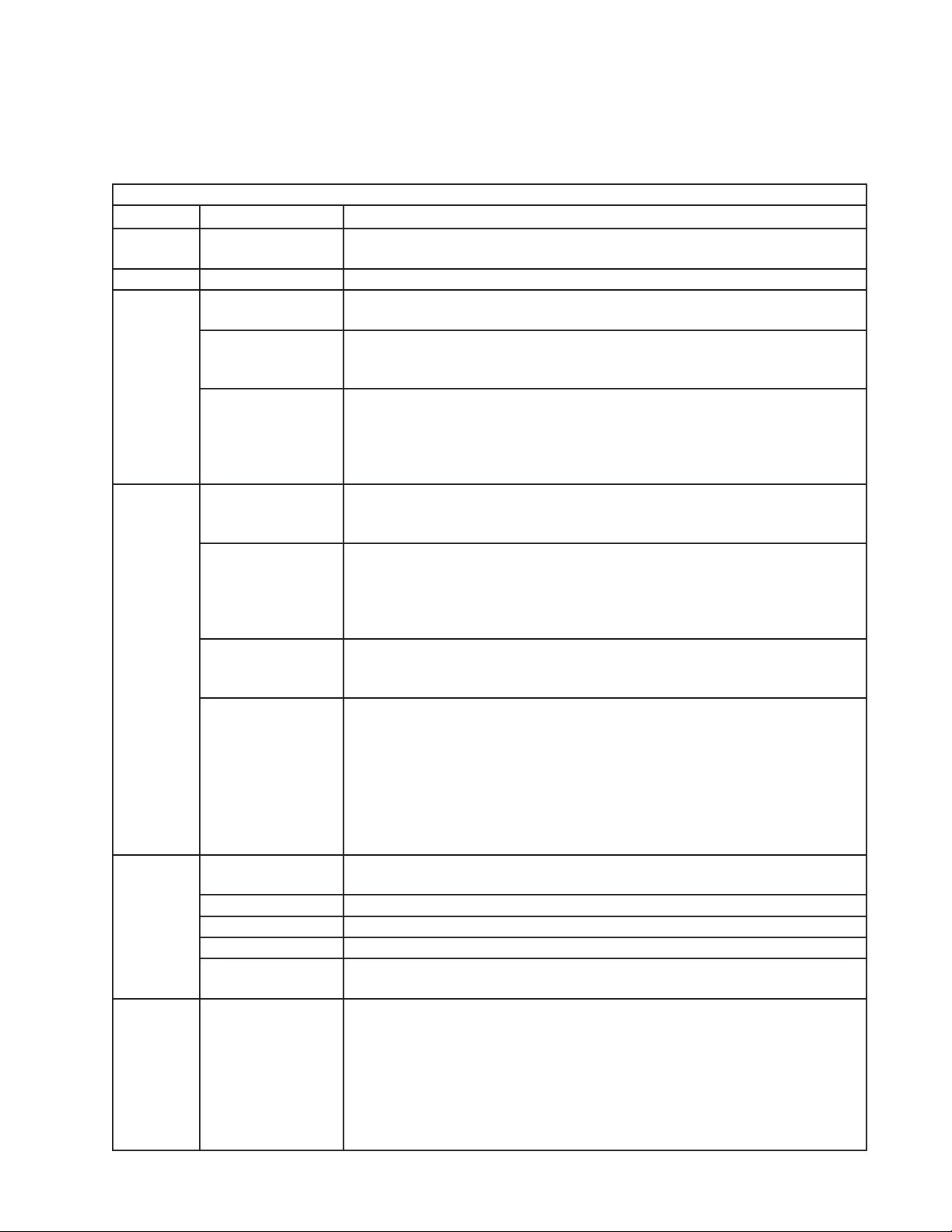
57
A. Maintenance Schedule
The maintenance schedule below is a guideline. More frequent maintenance may be
required depending on water quality, the appliance's environment, and local sanitation
regulations.
Maintenance Schedule
Frequency Area Task
Daily Scoop Clean the ice scoop using a neutral cleaner. Rinse thoroughly after
cleaning.
Bi-Weekly Air Filters Inspect. Wash with warm water and neutral cleaner if dirty.
Monthly External Water
Filters
Check for proper pressure and change if necessary.
Icemaker Exterior Wipe down with a clean, soft cloth. Use a damp cloth containing a neutral
cleaner to wipe off oil or dirt build up. Clean any chlorine staining (rust
colored spots) using a non-abrasive cleanser.
Infrared Sensor
Lens; Underside of
Icemaker and Top
Kits; Bin Door and
Snout
Wipe down with a clean cloth and warm water.
Every 6
Months
Icemaker and
Dispenser Unit/Ice
Storage Bin
Clean and sanitize per the cleaning and sanitizing instructions provided in
the instruction manual or on maintenance label.
Evaporator
Condensate Drain
Pan and Gear
Motor Drain Pan
Wipe down with a clean cloth and warm water. Slowly pour one cup
of sanitizing solution (prepare as outlined in the sanitizing instructions
provided in the instruction manual) into the evaporator condensate drain
pan and then slowly pour one cup into the gear motor drain pan. Be careful
not to overow the pans. Repeat with a cup of clean water to rinse.
Icemaker and
Dispenser Unit/Ice
Storage Bin Drains
Check to make sure they are clear.
Extruding Head
Seal Bolts
Inspect for leakage around seal bolts. Tighten (see torque values below) or
replace as necessary. Seal bolts must be replaced once removed because
seal material is one-time use only. If new seal bolts do not have preapplied
threadlocker, apply Loctite243 or equivalent threadlocker to seal bolt
threads.
• Torque for F-1002 and Smaller: 11.1 ft-lb/15 N·m
• Torque for F-1501 and Larger: 25.8 ft-lb/35 N·m Tighten 2 times. Allow at
least 5 sec. in between each tightening.
Yearly Inlet Water Valve
and Drain Valve
Close the water supply line shut-off valve and drain the water system. Clean
the inlet water valve screen and clean and inspect the drain valve.
Water Hoses Inspect the water hoses and clean/replace if necessary.
Condenser Inspect. Clean if necessary by using a brush or vacuum cleaner.
Icemaker Inspect for oil spots, loose components, fasteners, and wires.
Upper Bearing
(extruding head)
Check for wear using .02" round stock or pin gauge. Replace both upper
bearing and lower bearing if wear exceeds factory recommendations.
After
3 Years,
then Yearly
Upper Bearing
(extruding head);
Lower Bearing
and O-Ring
(lower housing);
Mechanical
Seal; Evaporator
Cylinder; Auger
Inspect. Replace both upper bearing and lower bearing if wear exceeds
factory recommendations. Replace the mechanical seal if the seal's contact
surfaces are worn, cracked, or scratched.

58
VI. Disposal
The appliance contains refrigerant and must be disposed of in accordance with
applicable national, state, and local codes and regulations. Refrigerant must be
recovered by properly certied service personnel.
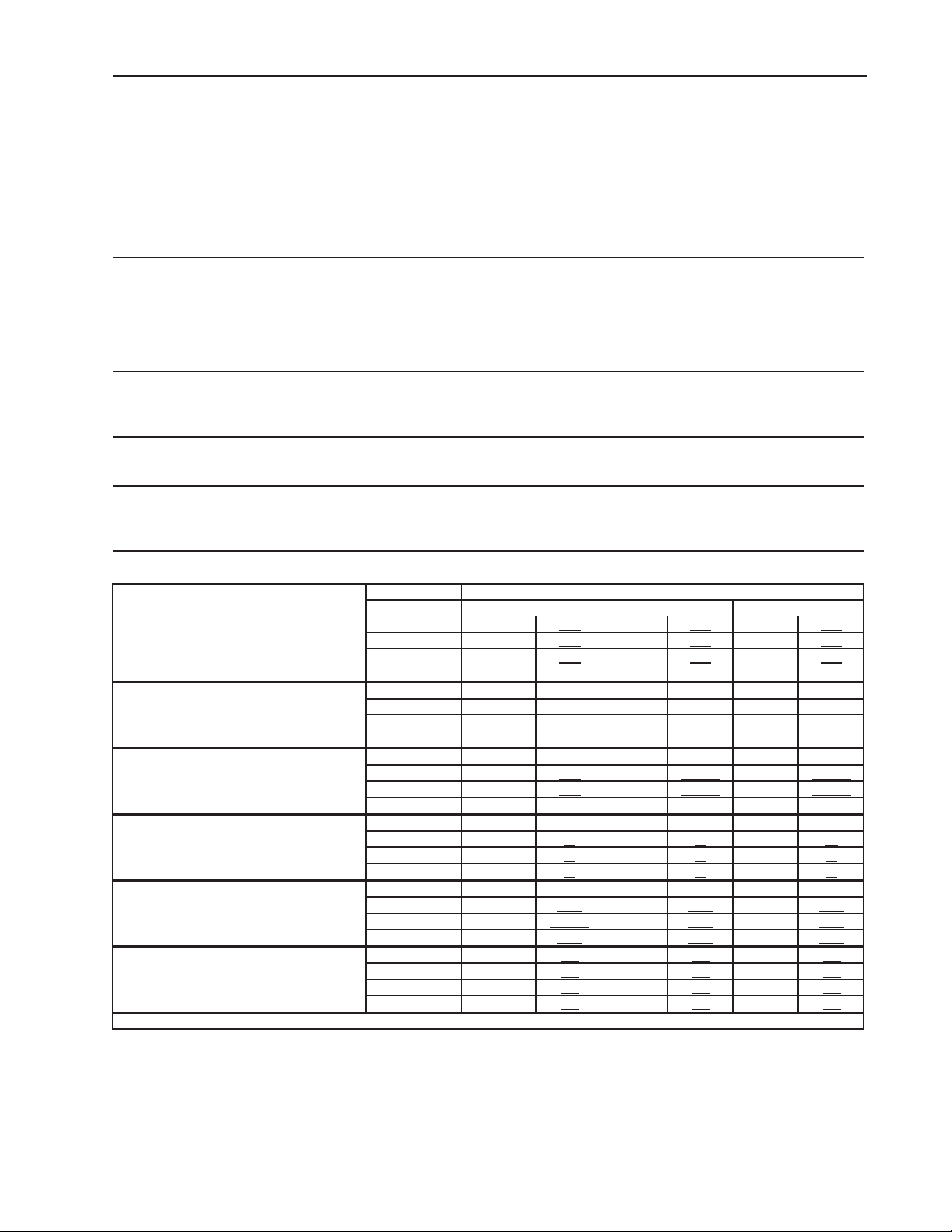
59
VII. Technical Information
We reserve the right to make changes in specications and design without prior notice.
A. Specication & Performance Data Sheets
Note: The data in bold should be used for reference.
1a. F-1001MAH
Specification Shee
t
AC SUPPLY VOLTAGE 208-230/60/1 (3 wire with neutral)
4.2 RLA 34 LRA 5.9 RLA 46 LRA
GEAR MOTOR 120 V 3 FLA 1/4 HP
FAN MOTOR 115 V 0.85FLA 1/15 HP
OTHER 120 V 0.03A
MAXIMUM FUSE SIZE 15 A
MAX. HACR BREAKER (USA ONLY) 15 A
MAX. CIRC. BREAKER (CANADA ONLY) 15 A
MINIMUM CIRCUIT AMPACITY 15 A
ELECTRIC & WATER CONSUMPTION 90/70°F 70/50°F
ELECTRIC W (kWH/100 lbs.) 1755 (5.7) 1530 (3.8)
WATER gal./24HR (gal./100 lbs.) 89 (12) 116 (12)
SHAPE OF ICE Flake
ICE HARDNESS Approx. 70%, Ice (32/21 (90/70), Conductivity 200 µs/cm)
BIN CONTROL SYSTEM Proximity Switch (BC (Mechanical))
REFRIGERANT CHARGE R-404A
Performance Data Shee
t
APPROXIMATE ICE Ambient
PRODUCTION PER 24 HR. Temp. °F (°C)
70 (21) 970 440
930 422 890 404
80 (26) 855 388 820 372 785 357
90 (32) 755 342 740 336 695 314
lbs./day ( kg/day
)
100 (38) 665 301 635 289 595 207
APPROXIMATE ELECTRIC 70 (21) 1160 -- 1165 -- 1170 --
CONSUMPTION 80 (26) 1175 -- 1185 -- 1190 --
90 (32) 1195 -- 1200 -- 1205 --
watts 100 (38) 1210 -- 1215 -- 1220 --
APPROXIMATE WATER 70 (21) 116 440
112 422.00 107 404.00
CONSUMPTION PER 24 HR. 80 (26) 103 388 98 372.00 94 357.00
90 (32) 90 342 89 336.00 83 314.00
gal. / day (l/day
)
100 (38) 80 301 76 289.00 71 270.00
EVAPORATOR OUTLET TEMP. 70 (21) 19 -7 19 -7 19 -7
°F (°C) 80 (26) 19 -7 23 -5 23 *5
90 (32) 23 -5 23 -5 25 -4
100 (38) 25 -4 25 -4 25 -4
HEAD PRESSURE 70 (21) 213 15.0 213 15.0 213 15.0
PSIG (kg/sq.cmG) 80 (26) 244 17.1 244 17.1 244 17.1
90 (32) 274 1933.0 274 19.3 274 19.3
100 (38) 315 22.1 315 22.1 315 22.1
SUCTION PRESSURE 70 (21) 32 2.3 32 2.3 32 2.3
PSIG (kg/sq.cmG) 80 (26) 35 2.5 35 2.5 35 2.5
90 (32) 38 2.6 38 2.6 38 2.6
100 (38) 41 2.9 41 2.9 41 2.9
Total HEAT OF REJECTION
1 lb. 12 oz. (800g) 2 lb. 4.1 oz. (1035g)
9100 BTU/h (AT 90°F /WT 70°F)
50 (10) 70 (21) 90 (32)
Water Temp. °F (°C)
COMPRESSOR 240 V
Aux. Code C-1
and Earlier
Aux. Code C-2
and Later
ENG.F-013.0.1196
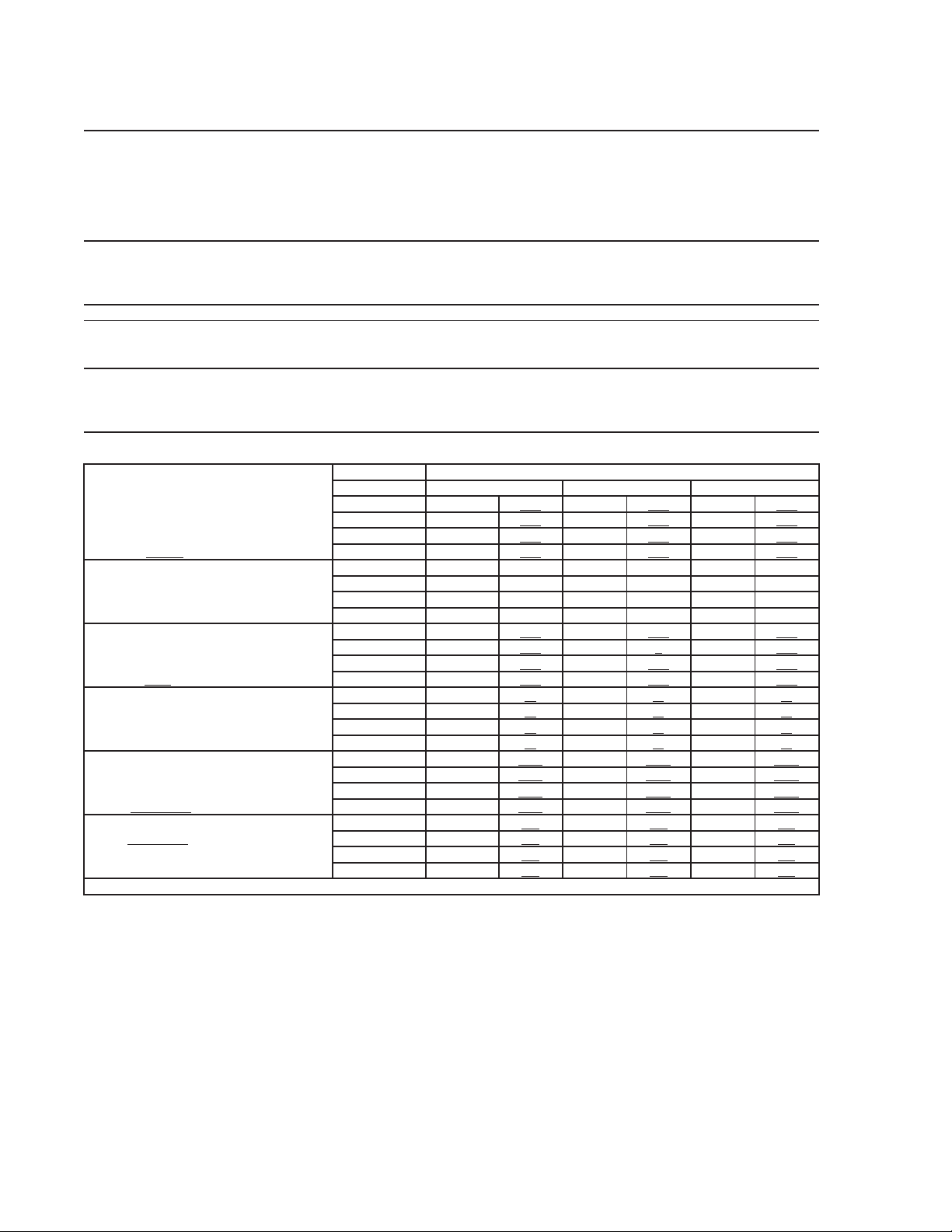
60
1b. F-1001MAH-C
Specification Shee
t
AC SUPPLY VOLTAGE 208-230/60/1 (3 wire with neutral)
4.2 RLA 34 LRA 5.9 RLA 46 LRA
GEAR MOTOR 120 V 3 FLA 1/4 HP
FAN MOTOR 115 V 0.85FLA 1/15 HP
OTHER 120 V 0.03A
MAXIMUM FUSE SIZE 15 A
MAX. HACR BREAKER (USA ONLY) 15 A
MAX. CIRC. BREAKER (CANADA ONLY) 15 A
MINIMUM CIRCUIT AMPACITY 15 A
SHAPE OF ICE Cubelet
ELECTRIC & WATER CONSUMPTION 90/70°F 70/50°F
ELECTRIC W (kWH/100 lbs.) 1516 (5.63) 1469 (3.9)
WATER gal./24HR (gal./100 lbs.) 80 (12) 103 (12)
SHAPE OF ICE Cubelet
ICE QUALITY Approx. 80%, Ice (90/70°F, Conductivity 200 µs/cm)
BIN CONTROL SYSTEM Proximity Switch (BC (Mechanical))
REFRIGERANT CHARGE R-404A
Performance Data Shee
t
APPROXIMATE Ambient
ICE PRODUCTION Temp. °F (°C)
PER 24 HR. 70 (21) 910 413
860 391 830 376
80 (26) 800 362 770 348 740 335
90 (32) 630 322 680 308 660 298
lbs./DAY kg/da
y
100 (38) 610 287 610 276 575 261
APPROXIMATE ELECTRIC 70 (21) 1469 -- 1476 -- 1482 --
CONSUMPTION 80 (26) 1489 -- 1496 -- 1503 --
90 (32) 1509 -- 1516 -- 1517 --
watts 100 (38) 1518 -- 1519 -- 1520 --
APPROXIMATE WATER 70 (21) 103 390
99 373 95 359
CONSUMPTION PER 24 HR. 80 (26) 92 346 88 1 85 321
90 (32) 82 309 80 302 76 287
gal. / day l/da
y
100 (38) 73 277 71 266 66 249
EVAPORATOR OUTLET TEMP. 70 (21) 18 -8 18 -8 18 -8
°F (°C) 80 (26) 18 -8 23 -5 23 -5
90 (32) 23 -5 23 -5 27 -3
100 (38) 27 -3 27 -3 27 -3
HEAD PRESSURE 70 (21) 209 14.7 209 14.7 209 14.7
80 (26) 243 17.1 243 17.1 243 17.1
90 (32) 277 19.5 277 19.5 277 19.5
PSIG kg/sq.cmG
100 (38) 317 22.3 317 22.3 217 22.3
SUCTION PRESSURE 70 (21) 32 2.2 32 2.2 32 2.2
PSIG kg/sq.cmG
80 (26) 35 2.5 35 2.5 35 2.5
90 (32) 38 2.7 38 2.7 38 2.7
100 (38) 41 2.9 41 2.9 41 2.9
TOTAL HEAT OF REJECTION
9050 BTU/h (AT 90°F /WT 70°F)
50 (10) 70 (21) 90 (32)
Water Temp. (F)
COMPRESSOR 240 V
Aux. Code C-1
and Earlier
Aux. Code C-2
and Later
1 lb. 12 oz. (800g) 2 lb. 4.1 oz. (1035g)
ENG.F-013.0.1196
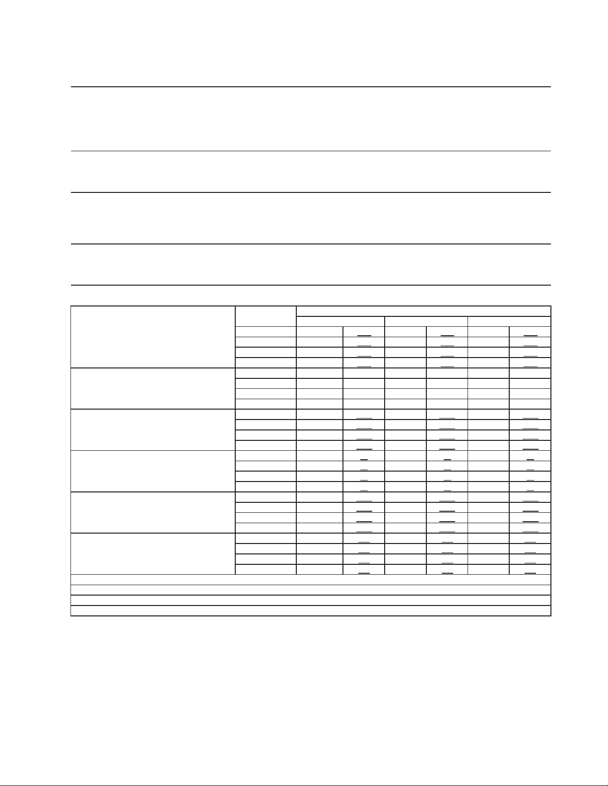
61
2a. F-1001MWH
Specification Shee
t
AC SUPPLY VOLTAGE 208-230/60/1 (3 wire with neutral)
4.2 RLA 34 LRA 5.9 RLA 46 LRA
GEAR MOTOR 120 V 3 FLA 1/4 HP
OTHER 120 V 0.03A
MAXIMUM FUSE SIZE 15 A
MAX. HACR BREAKER (USA ONLY) 15 A
MAX. CIRC. BREAKER (CANADA ONLY) 15 A
MINIMUM CIRCUIT AMPACITY 15 A
ELECTRIC & WATER CONSUMPTION 90/70°F 70/50°F
ELECTRIC W (kWH/100 lbs.) 1248 (4.24) 1245 (3.1)
POTABLE WATER 91 (12) 107 (12)
WATER-COOLED CONDENSER 480 (66) 303 (34)
gal./24HR (gal./100 lbs.)
SHAPE OF ICE Flake
ICE HARDNESS Approx. 70%, Ice (32/21 (90/70), Conductivity 200 µs/cm)
BIN CONTROL SYSTEM Proximity Switch (BC (Mechanical))
REFRIGERANT CHARGE R-404A
Performance Data Shee
t
APPROXIMATE Ambient
ICE PRODUCTION Temp. °F (°C)
PER 24 HR. 70 (21) 890 404 855 389 840 380
80 (26) 820 372 805 364 785 356
90 (32) 770 349 755 342 735 334
lbs./DAY ( kg/day) 100 (38) 720 327 705 320 655 297
APPROXIMATE ELECTRIC 70 (21) 1155 -- 1160 -- 1185 --
CONSUMPTION 80 (26) 1155 -- 1160 -- 1185 --
90 (32) 1155 -- 1160 -- 1185 --
watts 100 (38) 1155 -- 1160 -- 1185 --
APPROXIMATE WATER 70 (21) 410 1.86
526 2.39 811 3.69
CONSUMPTION PER 24 HR. 80 (26) 427 1.94 548 2.49 853 3.88
90 (32) 443 2.01 571 2.59 898 4.08
gal. / day (l/day) 100 (38) 461 2.09 599 2.72 989 4.49
EVAPORATOR OUTLET TEMP. 70 (21) 23 -5 23 -5 25 -4
°F (°C) 80 (26) 23 -5 23 -5 25 -4
90 (32) 23 -5 23 -5 25 -4
100 (38) 23 -5 23 -5 25 -4
HEAD PRESSURE 70 (21) 263 18.5 266 18.7 269 18.9
PSIG (kg/sq.cmG) 80 (26) 263 18.5 266 18.7 269 18.9
90 (32) 263 18.5 266 18.7 269 18.9
100 (38) 263 18.5 266 18.7 269 18.9
SUCTION PRESSURE 70 (21) 33 2.3 34 2.4 35 2.5
PSIG (kg/sq.cmG) 80 (26) 33 2.3 34 2.4 35 2.5
90 (32) 33 2.3 34 2.4 35 2.5
100 (38) 33 2.3 34 2.4 35 2.5
WATER FLOW FOR CONDENSER 38 gal/h (AT 100°F /WT 90°F)
PRESSURE DROP OF COOLING WATER LINE Less than 7 PSIG
HEAT OF REJECTION FROM CONDENSER 7110 BTU/h (AT 90°F /WT 70°F)
HEAT OF REJECTION FROM COMPRESSOR 1340 BTU/h (AT 90°F /WT 70°F)
50 (10) 70 (21) 90 (32)
Water Temp. °F (°C)
COMPRESSOR 240 V
Aux. Code C-1
and Earlier
Aux. Code C-2
and Later
15 oz. (425g) 12.3 oz. (349g)
ENG.F-013.0.1196
62
2b. F-1001MWH-C
Specification Shee
t
AC SUPPLY VOLTAGE 208-230/60/1 (3 wire with neutral)
4.2 RLA 34 LRA 5.9 RLA 46 LRA
GEAR MOTOR 120 V 3 FLA 1/4 HP
OTHER 120 V 0.03A
MAXIMUM FUSE SIZE 15 A
MAX. HACR BREAKER (USA ONLY) 15 A
MAX. CIRC. BREAKER (CANADA ONLY) 15 A
MINIMUM CIRCUIT AMPACITY 15 A
ELECTRIC & WATER CONSUMPTION 90/70°F 70/50°F
ELECTRIC W (kWH/100 lbs.) 1265 (4.3) 1264 (3.8)
POTABLE WATER 82 (12) 95 (12)
WATER-COOLED CONDENSER 492 (72) 303 (34)
gal./24HR (gal./100 lbs.)
SHAPE OF ICE Cubelet
ICE HARDNESS Approx. 80%, Ice (90/70°F, Conductivity 200 µs/cm)
BIN CONTROL SYSTEM Proximity Switch (BC (Mechanical))
REFRIGERANT CHARGE R-404A
Performance Data Shee
t
APPROXIMATE Ambient
ICE PRODUCTION Temp. °F (°C)
PER 24 HR. 70 (21) 790 358
760 346 750 340
80 (26) 735 333 720 327 710 322
90 (32) 695 316 685 311 670 304
lbs./DAY ( kg/day) 100 (38) 660 299 645 294 600 272
APPROXIMATE ELECTRIC 70 (21) 1160 -- 1170 -- 1185 --
CONSUMPTION 80 (26) 1160 -- 1170 -- 1185 --
90 (32) 1160 -- 1170 -- 1185 --
watts 100 (38) 1160 -- 1170 -- 1185 --
APPROXIMATE WATER 70 (21) 398 1.81
534 2.43 859 3.91
CONSUMPTION PER 24 HR. 80 (26) 414 1.88 554 2.52 898 4.08
(TOTAL) 90 (32) 427 1.94 574 2.61 939 4.27
gal. / day (l/day) 100 (38) 442 2.01 598 2.72 1032 4.69
EVAPORATOR OUTLET TEMP. 70 (21) 23 -5 23 -5 25 -4
°F (°C) 80 (26) 23 -5 23 -5 25 -4
90 (32) 23 -5 23 -5 25 -4
100 (38) 23 -5 23 -5 25 -4
HEAD PRESSURE 70 (21) 263 18.5 266 18.7 269 18.9
80 (26) 263 18.5 266 18.7 269 18.9
90 (32) 263 18.5 266 18.7 269 18.9
PSIG (kg/sq.cmG) 100 (38) 263 18.5 266 18.7 269 18.9
SUCTION PRESSURE 70 (21) 33 2.3 34 2.4 35 2.5
PSIG (kg/sq.cmG) 80 (26) 33 2.3 34 2.4 35 2.5
90 (32) 33 2.3 34 2.4 35 2.5
100 (38) 33 2.3 34 2.4 35 2.5
WATER FLOW FOR CONDENSER 40 gal/h (AT 90°F /WT 70°F)
PRESSURE DROP OF COOLING WATER LINE Less than 7 PSIG
HEAT OF REJECTION FROM CONDENSER 7110 BTU/h (AT 90°F /WT 70°F)
HEAT OF REJECTION FROM COMPRESSOR 1340 BTU/h (AT 90°F /WT 70°F)
COMPRESSOR 240 V
Aux. Code C-1 Aux. Code C-2
15 oz. (425g) 12.3 oz. (349g)
50 (10) 70 (21) 90 (32)
Water Temp. °F (°C)
ENG.F-013.0.1196
63
3a. F-1001MRH
Specification Sheet
AC SUPPLY VOLTAGE 208-230/60/1 (3 wire with neutral)
COMPRESSOR 240 V 4.2 RLA 34 LRA
GEAR MOTOR 120 V 3 FLA 1/4 HP
FAN MOTOR REMOTE 120 V 3A MAX
OTHER 120 V 0.03A
MAXIMUM FUSE SIZE 15 A
MAX. HACR BREAKER (USA ONLY) 15 A
MAX. CIRC. BREAKER (CANADA ONLY) 15 A
MINIMUM CIRCUIT AMPACITY 15 A
ELECTRIC & WATER CONSUMPTION 90/70°F 70/50°F
ELECTRIC W (kWH/100 lbs.) 1520 (5.60) 1570 (4.1)
WATER gal./24HR (gal./100 lbs.) 89 (12) 111(12)
SHAPE OF ICE Flake
ICE HARDNESS Approx. 70%, Ice (32/21 (90/70), Conductivity 200 µs/cm)
BIN CONTROL SYSTEM Proximity Switch (BC (Mechanical))
CONDENSER Air-cooled Remote Condenser unit URC-5F Recommended
TOTAL REFRIGERANT CHARGE R-404A, 4 lb. 1 oz. (1850g)
(Ice Maker: 2 lb. 3 oz., Cond. Unit: 1 lb. 14 oz. )
Performance Data Shee
t
APPROXIMATE Ambient
ICE PRODUCTION Temp. °F (°C)
PER 24 HR. 70 (21) 930 422 895 407 865 393
80 (26) 835 379 805 366 780 353
90 (32) 750 341 745 338 700 317
lbs./DAY ( kg/day) 100 (38) 675 306 650 296 605 274
APPROXIMATE ELECTRIC 70 (21) 1285 -- 1285 -- 1290 --
CONSUMPTION 80 (26) 1290 -- 1290 -- 1290 --
90 (32) 1295 -- 1295 -- 1305 --
watts 100 (38) 1310 -- 1320 -- 1325 --
APPROXIMATE WATER 70 (21) 112 422 108 407 104 393
CONSUMPTION PER 24 HR. 80 (26) 100 379 97 366 93 353
90 (32) 90 341 89 338 84 317
gal. / day (l/day) 100 (38) 81 306 78 296 73 274
EVAPORATOR OUTLET TEMP. 70 (21) 23 -5 24 -4 25 -4
°F (°C) 80 (26) 25 -4 26 -3 26 -3
90 (32) 26 -3 27 -3 28 -2
100 (38) 28 -2 28 -2 28 -2
HEAD PRESSURE 70 (21) 221 15.5 221 15.5 221 15.5
PSIG (kg/sq.cmG) 80 (26) 239 16.8 239 16.8 239 16.8
90 (32) 256 18.0 256 18.0 256 18.0
100 (38) 295 20.7 295 20.7 295 20.7
SUCTION PRESSURE 70 (21) 33 2.3 33 2.3 33 2.3
PSIG (kg/sq.cmG) 80 (26) 35 2.4 35 2.4 35 2.4
90 (32) 36 2.5 36 2.5 36 2.5
100 (38) 39 2.7 39 2.7 39 2.7
CONDENSER VOLUME 74.5 cu in
HEAT OF REJECTION FROM CONDENSER 7660 BTU/h (AT 90°F /WT 70°F)
HEAT OF REJECTION FROM COMPRESSOR 1380 BTU/h (AT 90°F /WT 70°F)
50 (10) 70 (21) 90 (32)
Water Temp. °F (°C)
ENG.F-013.0.1196
64
3b. F-1001MRH-C
Specification Sheet
AC SUPPLY VOLTAGE 208-230/60/1 (3 wire with neutral)
4.2 RLA 34 LRA 5.9 RLA 46 LRA
GEAR MOTOR 120 V 3 FLA 1/4 HP
FAN MOTOR REMOTE 120 V 3A MAX
OTHER 120 V 0.03A
MAXIMUM FUSE SIZE 15 A
MAX. HACR BREAKER (USA ONLY) 15 A
MAX. CIRC. BREAKER (CANADA ONLY) 15 A
MINIMUM CIRCUIT AMPACITY 15 A
ELECTRIC & WATER CONSUMPTION 90/70°F 70/50°F
ELECTRIC W (kWH/100 lbs.) 1605 (5.08) 1610 (4.6)
WATER gal./24HR (gal./100 lbs.) 83 (12) 101(12)
SHAPE OF ICE Cubelet
ICE QUALITY Approx. 80%, Ice (90/70°F, Conductivity 200 µs/cm)
BIN CONTROL SYSTEM Proximity Switch (BC (Mechanical))
CONDENSER Air-cooled Remote Condenser unit URC-5F Recommended
REFRIGERANT CHARGE R-404A, 4 lb. 1 oz. (1850g)
(Ice Maker: 2 lb. 3 oz., Cond. Unit: 1 lb. 14 oz. )
Performance Data Sheet
APPROXIMATE Ambient
ICE PRODUCTION Temp. °F (°C)
PER 24 HR. 70 (21) 840 381 810 368 790 358
80 (26) 765 347 745 337 720 327
90 (32) 700 317 695 315 660 299
lbs./DAY ( kg/day) 100 (38) 640 290 620 282 575 261
APPROXIMATE ELECTRIC 70 (21) 1300 -- 1300 -- 1305 --
CONSUMPTION 80 (26) 1305 -- 1305 -- 1305 --
90 (32) 1310 -- 1310 -- 1320 --
watts 100 (38) 1325 -- 1335 -- 1340 --
APPROXIMATE WATER 70 (21) 101 381 98 368 95 358
CONSUMPTION PER 24 HR. 80 (26) 92 347 89 337 87 327
90 (32) 84 317 83 315 79 299
gal. / day (l/day) 100 (38) 77 290 75 282 69 261
EVAPORATOR OUTLET TEMP. 70 (21) 23 -5 24 -4 25 -4
°F (°C) 80 (26) 25 -4 26 -3 26 -3
90 (32) 26 -3 25 -4 28 -2
100 (38) 28 -2 28 -2 28 -2
HEAD PRESSURE 70 (21) 220 15.5 220 15.5 220 15.5
80 (26) 238 16.7 238 16.7 238 16.7
90 (32) 256 18.0 256 18.0 256 18.0
PSIG (kg/sq.cmG) 100 (38) 295 20.7 295 20.7 295 20.7
SUCTION PRESSURE 70 (21) 34 2.4 34 2.4 34 2.4
PSIG (kg/sq.cmG) 80 (26) 36 2.5 36 2.5 36 2.5
90 (32) 37 2.6 37 2.6 37 2.6
100 (38) 40 2.8 40 2.8 40 2.8
CONDENSER VOLUME 74.5 cu in
HEAT OF REJECTION FROM CONDENSER 7840 BTU/h (AT 90°F /WT 70°F)
HEAT OF REJECTION FROM COMPRESSOR 1400 BTU/h (AT 90°F /WT 70°F)
50 (10) 70 (21) 90 (32)
Water Temp. °F (°C)
COMPRESSOR 240 V
Aux. Code C-1
and Earlier
Aux. Code C-2
and Later
ENG.F-013.0.1196

65
4a. F-1501MAH
Specification Shee
t
AC SUPPLY VOLTAGE 208-230/60/1 (3 wire with neutral)
COMPRESSOR 208-230 V 9.3 RLA 56 LRA
GEAR MOTOR 120 V 5.6 FLA 400W
FAN MOTOR 115 V 1.0 FLA 1/15 HP
OTHER 120 V 0.03 A
MAXIMUM FUSE SIZE 20 A
MAX. HACR BREAKER (USA ONLY) 20 A
MAX. CIRC. BREAKER (CANADA ONLY) 20 A
MINIMUM CIRCUIT AMPACITY 20 A
ELECTRIC & WATER CONSUMPTION 90/70°F 70/50°F
ELECTRIC W (kWH/100 lbs.) 1863 (4.03) 1820 (2.74)
WATER gal./24HR (gal./100 lbs.) 140 (12) 191 (12)
SHAPE OF ICE Flake
ICE HARDNESS Approx. 70%, Ice (32/21 (90/70), Conductivity 200 µs/cm)
BIN CONTROL SYSTEM (PRIMARY) Photoelectric Sensor (BC1 (Infrared Sensor))
BIN CONTROL SYSTEM (SECONDARY) Proximity Switch (BC2 (Mechanical))
REFRIGERANT CHARGE R-404A, 2 lb. 5 oz. (1050g)
Performance Data Shee
t
APPROXIMATE Ambient
ICE PRODUCTION Temp. °F (°C)
PER 24 HR. 70 (21) 1590 721
1514 687 1447 656
80 (26) 1382 627 1321 599 1262 572
90 (32) 1206 547 1110 503 1100 499
lbs./DAY kg/day
100 (38) 1051 477 1005 456 945 429
APPROXIMATE ELECTRIC 70 (21) 1820 -- 1826 -- 1832 --
CONSUMPTION 80 (26) 1838 -- 1845 -- 1851 --
90 (32) 1857 -- 1863 -- 1867 --
watts 100 (38) 1872 -- 1876 -- 1880 --
APPROXIMATE WATER 70 (21) 191 721 182 687 174 656
CONSUMPTION PER 24 HR. 80 (26) 166 627 159 599 152 572
90 (32) 145 547 140 531 132 499
gal. / day l/day
100 (38) 126 477 121 456 113 429
EVAPORATOR OUTLET TEMP. 70 (21) 16 -9 16 -9 16 -9
°F (°C) 80 (26) 16 -9 18 -8 18 -8
90 (32) 18 -8 18 -8 19 -7
100 (38) 19 -7 19 -7 19 -7
HEAD PRESSURE 70 (21) 210 14.8 210 14.8 210 14.8
PSIG kg/sq.cmG 80 (26) 240 16.9 240 16.9 240 16.9
90 (32) 270 19.0 270 19.0 270 19.0
100 (38) 310 21.8 310 21.8 310 21.8
SUCTION PRESSURE 70 (21) 35 2.5 35 2.5 35 2.5
PSIG kg/sq.cmG 80 (26) 38 2.6 38 2.6 38 2.6
90 (32) 40 2.8 40 2.8 40 2.8
100 (38) 42 3.0 42 3.0 42 3.0
TOTAL HEAT OF REJECTION 15,323 BTU/h (AT 90 F /WT 70 F)
Water Temp. °F (°C)
50 (10) 70 (21) 90 (32)
ENG.F-013.0.1196
66
4b. F-1501MAH-C
Specification Sheet
AC SUPPLY VOLTAGE 208-230/60/1 (3 wire with neutral)
COMPRESSOR 208-230 V 9.3 RLA 56 LRA
GEAR MOTOR 120 V 5.6 FLA 400W
FAN MOTOR 115 V 1.0 FLA 1/15 HP
OTHER 120 V 0.03 A
MAXIMUM FUSE SIZE 20 A
MAX. HACR BREAKER (USA ONLY) 20 A
MAX. CIRC. BREAKER (CANADA ONLY) 20 A
MINIMUM CIRCUIT AMPACITY 20 A
ELECTRIC & WATER CONSUMPTION 90/70°F 70/50°F
ELECTRIC W (kWH/100 lbs.) 1863 (5.36) 1820 (3.36)
WATER gal./24HR (gal./100 lbs.) 119 (12) 156 (12)
SHAPE OF ICE Cubelet
ICE QUALITY Approx. 80%, Ice (90/70°F, Conductivity 200 µs/cm)
BIN CONTROL SYSTEM (PRIMARY) Photoelectric Sensor (BC1 (Infrared Sensor))
BIN CONTROL SYSTEM (SECONDARY) Proximity Switch (BC2 (Mechanical))
REFRIGERANT CHARGE R-404A, 2 lb. 5 oz. (1050g)
Performance Data Sheet
APPROXIMATE Ambient
ICE PRODUCTION Temp. °F (°C)
PER 24 HR. 70 (21) 1300 590
1245 565 1194 542
80 (26) 1145 520 1099 498 1054 478
90 (32) 1011 458 939 426 930 422
lbs./DAY kg/day
100 (38) 892 404 855 388 800 363
APPROXIMATE ELECTRIC 70 (21) 1820 -- 1826 -- 1832 --
CONSUMPTION 80 (26) 1838 -- 1845 -- 1851 --
90 (32) 1857 -- 1863 -- 1867 --
watts 100 (38) 1872 -- 1876 -- 1880 --
APPROXIMATE WATER 70 (21) 156 590 149 565 143 542
CONSUMPTION PER 24 HR. 80 (26) 138 520 132 498 127 478
90 (32) 121 458 119 449 112 422
gal. / day l/day
100 (38) 107 404 103 388 96 363
EVAPORATOR OUTLET TEMP. 70 (21) 16 -9 16 -9 16 -9
°F (°C) 80 (26) 16 -9 18 -8 18 -8
90 (32) 18 -8 18 -8 19 -7
100 (38) 19 -7 19 -7 19 -7
HEAD PRESSURE 70 (21) 210 14.8 210 14.8 210 14.8
PSIG kg/sq.cmG 80 (26) 240 16.9 240 16.9 240 16.9
90 (32) 270 19.0 270 19.0 270 19.0
100 (38) 310 21.8 310 21.8 310 21.8
SUCTION PRESSURE 70 (21) 35 2.5 35 2.5 35 2.5
PSIG kg/sq.cmG 80 (26) 38 2.6 38 2.6 38 2.6
90 (32) 40 2.8 40 2.8 40 2.8
100 (38) 42 3.0 42 3.0 42 3.0
TOTAL HEAT OF REJECTION 15,323 BTU/h (AT 90 F /WT 70 F)
Water Temp. °F (°C)
50 (10) 70 (21) 90 (32)
ENG.F-013.0.1196
67
5a. F-1501MWH
Specification Sheet
AC SUPPLY VOLTAGE 208-230/60/1 (3 wire with neutral)
COMPRESSOR 208-230 V 9.3 RLA 56 LRA
GEAR MOTOR 120 V 5.6 FLA 400W
CABINET FAN MOTOR 115 V 0.51FLA 8W
OTHER 120 V 0.03A
MAXIMUM FUSE SIZE 20 A
MAX. HACR BREAKER (USA ONLY) 20 A
MAX. CIRC. BREAKER (CANADA ONLY) 20 A
MINIMUM CIRCUIT AMPACITY 20 A
ELECTRIC & WATER CONSUMPTION 90/70°F 70/50°F
ELECTRIC W (kWH/100 lbs.) 1667 (3.40)
1754 (2.88)
POTABLE WATER 146 (12.0)
175 (12.0)
WAER COOLED CONDENSER 831 (65)
481 (33)
gal./24HR (gal./100 lbs.)
SHAPE OF ICE Flake
ICE HARDNESS Approx. 70%, Ice (32/21 (90/70), Conductivity 200 µs/cm)
BIN CONTROL SYSTEM (PRIMARY) Photoelectric Sensor (BC1 (Infrared Sensor))
BIN CONTROL SYSTEM (SECONDARY) Proximity Switch (BC2 (Mechanical))
REFRIGERANT CHARGE R-404A, 1 lb. 4 oz. (575g)
Performance Data Sheet
APPROXIMATE Ambient
ICE PRODUCTION Temp. °F (°C)
PER 24 HR.
70 (21)
1460 662 1446 656 1409 639
80 (26)
1374 623 1340 608 1306 592
90 (32)
1273 578 1265 574 1210 549
lbs./day ( kg/day)
100 (38)
1180 535 1150 522 1095 497
APPROXIMATE ELECTRIC
70 (21)
1754 -- 1742 -- 1729 --
CONSUMPTION
80 (26)
1717 -- 1704 -- 1692 --
90 (32)
1679 -- 1667 -- 1668 --
watts
100 (38)
1668 -- 1669 -- 1669 --
APPROXIMATE WATER
70 (21)
658 2492 996 3769 1663 6295
CONSUMPTION PER 24 HR.
80 (26)
648 2453 983 3721 1651 6248
TOTAL
90 (32)
636 2407 974 3687 1639 6205
gal. / day (l/day)
100 (38)
625 2364 960 3635 1625 6152
EVAPORATOR OUTLET TEMP.
70 (21)
5 (-15) 5 (-15) 5 (-15)
°F (°C)
80 (26)
6 (-15) 6 (-15) 6 (-15)
90 (32)
6 (-15) 6 (-15) 6 (-15)
100 (38)
6 (-15) 6 (-15) 6 (-15)
HEAD PRESSURE
70 (21)
270 19.0 271 19.0 271 19.1
PSIG (kg/cm2G)
80 (26)
272 19.1 273 19.2 273 19.2
90 (32)
274 19.3 275 19.3 275 19.3
100 (38)
276 19.4 276 19.4 277 19.4
SUCTION PRESSURE
70 (21)
38 2.6 38 2.7 38 2.7
PSIG (kg/cm2G)
80 (26)
38 2.7 38 2.7 38 2.7
90 (32)
39 2.7 39 2.7 39 2.7
100 (38)
39 2.7 39 2.8 39 2.8
WATER FLOW FOR CONDENSER 34 gal/h (AT 90°F/WT 70°F)
PRESSURE DROP OF COOLING WATER LINE Less than 7 PSIG
HEAT OF REJECTION FROM CONDENSER 10100 BTU/h (AT 90°F/WT 70°F)
HEAT OF REJECTION FROM COMPRESSOR 1800 BTU/h (AT 90°F/WT 70°F)
Water Temp. °F (°C)
50 (10) 70 (21) 90 (32)
ENG.F-013.0.1196
68
5b. F-1501MWH-C
Specification Sheet
AC SUPPLY VOLTAGE 208-230/60/1 (3 wire with neutral)
COMPRESSOR 208-230 V 9.3 RLA 56 LRA
GEAR MOTOR 120 V 5.6 FLA 400W
CABINET FAN MOTOR 115 V 0.51FLA 8W
OTHER 120 V 0.03A
MAXIMUM FUSE SIZE 20 A
MAX. HACR BREAKER (USA ONLY) 20 A
MAX. CIRC. BREAKER (CANADA ONLY) 20 A
MINIMUM CIRCUIT AMPACITY 20 A
ELECTRIC & WATER CONSUMPTION 90/70°F 70/50°F
ELECTRIC W (kWH/100 lbs.) 1780 (3.95) 1796 (3.57)
POTABLE WATER 118 (12.0) 145 (12.0)
WATER-COOLED CONDENSER 719 (73.0) 472 (39.0)
gal./24HR (gal./100 lbs.)
SHAPE OF ICE Cubelet
ICE QUALITY Approx. 80%, Ice (90/70°F, Conductivity 200 µs/cm)
BIN CONTROL SYSTEM (PRIMARY) Photoelectric Sensor (BC1 (Infrared Sensor))
BIN CONTROL SYSTEM (SECONDARY) Proximity Switch (BC2 (Mechanical))
REFRIGERANT CHARGE R-404A, 1 lb.4oz. (575g)
Performance Data Sheet
APPROXIMATE
Ambient
ICE PRODUCTION Temp. °F (°C)
PER 24 HR. 70 (21) 1208 548
1211 549 1184 537
80 (26) 1158 525 1132 514 1107 502
90 (32) 1083 491 1096 497 1035 469
lbs./DAY kg/day
100 (38) 1012 459 990 449 928 421
APPROXIMATE ELECTRIC 70 (21) 1796 -- 1794 -- 1791 --
CONSUMPTION 80 (26) 1789 -- 1787 -- 1785 --
90 (32) 1782 -- 1780 -- 1786 --
watts 100 (38) 1791 -- 1797 -- 1802 --
APPROXIMATE WATER 70 (21) 617 2336 946 3579 1595 6038
CONSUMPTION PER 24 HR. 80 (26) 611 2313 936 3543 1586 6003
TOTAL 90 (32) 602 2279 932 3526 1577 5970
gal. / day l/day
100 (38) 594 2246 919 3478 1564 5921
EVAPORATOR OUTLET TEMP. 70 (21) 6 -15 6 -15 6 -15
°F (°C) 80 (26) 6 -15 6 -15 6 -15
90 (32) 6 -15 6 -15 6 -14
100 (38) 6 -14 6 -14 6 -14
HEAD PRESSURE 70 (21) 270 19.0 271 19.0 271 19.1
PSIG kg/sq.cmG
80 (26) 272 19.1 272 19.1 273 19.2
90 (32) 273 19.2 274 19.3 275 19.3
100 (38) 275 19.3 276 19.4 277 19.4
SUCTION PRESSURE 70 (21) 36 2.6 36 2.6 36 2.6
PSIG kg/sq.cmG
80 (26) 36 2.6 37 2.6 37 2.6
90 (32) 37 2.6 37 2.6 37 2.6
100 (38) 38 2.7 38 2.7 39 2.7
WATER FLOW FOR CONDENSER 33 gal/h (AT 100°F /WT 90°F)
PRESSURE DROP OF COOLING WATER LINE Less than 10 PSIG
HEAT OF REJECTION FROM CONDENSER 9500 BTU/h (AT 90°F/WT 70°F)
HEAT OF REJECTION FROM COMPRESSOR 1800 BTU/h (AT 90°F/WT 70°F)
Water Temp. °F (°C)
50 (10) 70 (21) 90 (32)
ENG.F-013.0.1196
69
6a. F-1501MRH
Specification Sheet
AC SUPPLY VOLTAGE 208-230/60/1 (3 wire with neutral)
COMPRESSOR 208-230 V 9.3 RLA 56 LRA
GEAR MOTOR 120 V 5.6 FLA 400W
CABINET FAN MOTOR 115 V 0.51 FLA 8W
REMOTE FAN MOTOR 120 V 3.0 A MAX.
OTHER 120 V 0.03 A
MAXIMUM FUSE SIZE 20 A
MAX. HACR BREAKER (USA ONLY) 20 A
MAX. CIRC. BREAKER (CANADA ONLY) 20 A
MINIMUM CIRCUIT AMPACITY 20 A
ELECTRIC & WATER CONSUMPTION 90/70°F 70/50°F
ELECTRIC W (kWH/100 lbs.) 2015(3.85) 2010 (3.01)
WATER gal./24HR (gal./100 lbs.) 156 (12) 190 (12)
SHAPE OF ICE Flake
ICE QUALITY Approx. 70%, Ice (90/70°F, Conductivity 200 µs/cm)
BIN CONTROL SYSTEM (PRIMARY) Photoelectric Sensor (BC1 (Infrared Sensor))
BIN CONTROL SYSTEM (SECONDARY) Proximity Switch (BC2 (Mechanical))
CONDENSER Air-cooled Remote Condenser Unit URC-14F Recommended.
REFRIGERANT CHARGE R-404A, 9 lb. 9 oz. (4350g)
(Ice Maker: 5lb. 2oz., Cond. Unit: 4lb. 7oz.)
Performance Data Sheet
APPROXIMATE Ambient
ICE PRODUCTION Temp. °F (°C)
PER 24 HR. 70 (21) 1585 719
1532 695 1484 673
80 (26) 1439 653 1394 632 1351 613
90 (32) 1309 594 1237 561 1230 558
lbs./DAY kg/day
100 (38) 1192 541 1155 524 1070 485
APPROXIMATE ELECTRIC 70 (21) 2010 -- 2011 -- 2011 --
CONSUMPTION 80 (26) 2012 -- 2013 -- 2014 --
90 (32) 2014 -- 2015 -- 2021 --
watts 100 (38) 2028 -- 2034 -- 2040 --
APPROXIMATE WATER 70 (21) 190 719 184 695 178 673
CONSUMPTION PER 24 HR. 80 (26) 173 653 167 632 162 613
90 (32) 157 594 156 590 148 558
gal. / day kg/day
100 (38) 143 541 139 524 128 485
EVAPORATOR OUTLET TEMP. 70 (21) 19 -7 19 -7 19 -7
°F (°C) 80 (26) 19 -7 21 -6 21 -6
90 (32) 21 -6 21 -6 23 -5
100 (38) 23 -5 23 -5 23 -5
HEAD PRESSURE 70 (21) 215 15 215 15 215 15
PSIG kg/sq.cmG 80 (26) 228 16 228 16 228 16
90 (32) 240 17 240 17 240 17
100 (38) 275 19 275 19 275 19
SUCTION PRESSURE 70 (21) 36 3 36 3 36 3
PSIG kg/sq.cmG
80 (26) 38 3 38 3 38 3
90 (32) 40 3 40 3 40 3
100 (38) 42 3 42 3 42 3
TOTAL HEAT OF REJECTION FROM CONDENSER 13,194 BTU/h (AT 90 F /WT 70 F)
TOTAL HEAT OF REJECTION FROM UNIT 2,129 BTU/h (AT 90 F /WT 70 F)
Water Temp. °F (°C)
50 (10) 70 (21) 90 (32)
ENG.F-013.0.1196
70
6b. F-1501MRH-C
Specification Sheet
AC SUPPLY VOLTAGE 208-230/60/1 (3 wire with neutral)
COMPRESSOR 208-230 V 9.3 RLA 56 LRA
GEAR MOTOR 120 V 5.6 FLA 400W
CABINET FAN MOTOR 115 V 0.51 FLA 8W
REMOTE FAN MOTOR 120 V 3.0 A MAX.
OTHER 120 V 0.03 A
MAXIMUM FUSE SIZE 20 A
MAX. HACR BREAKER (USA ONLY) 20 A
MAX. CIRC. BREAKER (CANADA ONLY) 20 A
MINIMUM CIRCUIT AMPACITY 20 A
ELECTRIC & WATER CONSUMPTION 90/70°F 70/50°F
ELECTRIC W (kWH/100 lbs.) 1949 (4.35) 1947 (3.50)
WATER gal./24HR (gal./100 lbs.) 134 (12) 160 (12)
SHAPE OF ICE Cubelet
ICE QUALITY Approx. 80%, Ice (90/70°F, Conductivity 200 µs/cm)
BIN CONTROL SYSTEM (PRIMARY) Photoelectric Sensor (BC1 (Infrared Sensor))
BIN CONTROL SYSTEM (SECONDARY) Proximity Switch (BC2 (Mechanical))
CONDENSER Air-cooled Remote Condenser Unit URC-14F Recommended
REFRIGERANT CHARGE R-404A, 9 lb. 9 oz. (4350g)
(Ice Maker: 5lb. 2oz., Cond. Unit: 4lb. 7oz.)
Performance Data Sheet
APPROXIMATE Ambient
ICE PRODUCTION Temp. °F (°C)
PER 24 HR. 70 (21) 1335 606
1294 587 1258 571
80 (26) 1223 555 1188 539 1155 524
90 (32) 1123 509 1164 483 1060 481
lbs./DAY kg/day
100 (38) 1031 468 1002 454 925 420
APPROXIMATE ELECTRIC 70 (21) 2010 -- 2011 -- 2011 --
CONSUMPTION 80 (26) 2012 -- 2013 -- 2014 --
90 (32) 2014 -- 2015 -- 2021 --
watts 100 (38) 2028 -- 2034 -- 2040 --
APPROXIMATE WATER 70 (21) 160 606 155 587 151 571
CONSUMPTION PER 24 HR. 80 (26) 147 555 143 539 139 524
90 (32) 135 509 134 508 127 481
gal. / day l/day
100 (38) 124 468 120 454 111 420
EVAPORATOR OUTLET TEMP. 70 (21) 19 -7 19 -7 19 -7
°F (°C) 80 (26) 19 -7 21 -6 21 -6
90 (32) 21 -6 21 -6 23 -5
100 (38) 23 -5 23 -5 23 -5
HEAD PRESSURE 70 (21) 215 15 215 15 215 15
PSIG (kg/sq.cmG) 80 (26) 228 16 228 16 228 16
90 (32) 240 17 240 17 240 17
100 (38) 275 19 275 19 275 19
SUCTION PRESSURE 70 (21) 36 3 36 3 36 3
PSIG kg/sq.cmG
80 (26) 38 3 38 3 38 3
90 (32) 40 3 40 3 40 3
100 (38) 42 3
423423
TOTAL HEAT OF REJECTION FROM CONDENSER 13,194 BTU/h (AT 90 F /WT 70 F)
TOTAL HEAT OF REJECTION FROM UNIT 2,129 BTU/h (AT 90 F /WT 70 F)
Water Temp. °F (°C)
50 (10) 70 (21) 90 (32)
ENG.F-013.0.1196
71
7. F-2001MWH
Specification Sheet
AC SUPPLY VOLTAGE 208-230/60/1 (3 wire with neutral)
COMPRESSOR 208-230 V 10.8 RLA 96 LRA
GEAR MOTOR 120 V 5.6 FLA 400W
CABINET FAN MOTOR 115 V 0.51 FLA 8W
OTHER 120 V 0.03 A
MAXIMUM FUSE SIZE 30 A
MAX. HACR BREAKER (USA ONLY) 30 A
MAX. CIRC. BREAKER (CANADA ONLY) 30 A
MINIMUM CIRCUIT AMPACITY 30 A
ELECTRIC & WATER CONSUMPTION 90/70°F 70/50°F
ELECTRIC W (kWH/100 lbs.) 2510 (3.68) 2490 (2.9)
POTABLE WATER 207 (12) 243 (12)
WATER-COOLED CONDENSER 1165 (70) 735 (36)
gal./24HR (gal./100 lbs.)
SHAPE OF ICE Flake
ICE HARDNESS Approx. 70%, Ice (32/21 (90/70), Conductivity 200 µs/cm)
BIN CONTROL SYSTEM (PRIMARY) Photoelectric Sensor (BC1 (Infrared Sensor))
BIN CONTROL SYSTEM (SECONDARY) Proximity Switch (BC2 (Mechanical))
REFRIGERANT CHARGE R-404A, 2 lbs. (910g)
Performance Data Sheet
APPROXIMATE Ambient
ICE PRODUCTION Temp. (F)
PER 24 HR. 70 2030 (921) 1955 (887) 1915 (869)
80 1875 (851) 1835 (832) 1795 (814)
90 1760 (798) 1642 (745) 1685 (764)
lbs./DAY ( kg/day) 100 1650 (748) 1615 (733) 1500 (680)
APPROXIMATE ELECTRIC 70 2490 -- 2510 -- 2545 --
CONSUMPTION 80 2490 -- 2510 -- 2545 --
90 2490 -- 2510 -- 2545 --
watts 100 2490 -- 2510 -- 2545 --
APPROXIMATE WATER 70 981 (3.71) 1266 (4.79) 2057 (7.79)
CONSUMPTION PER 24 HR. 80 1023 (3.87) 1319 (4.99) 2163 (8.19)
(TOTAL) 90 1062 (4.02) 1374 (5.20) 2278 (8.62)
gal. / day (m3/day) 100 1105 (4.18) 1442 (5.46) 2513 (9.51)
EVAPORATOR OUTLET TEMP. 70 11 (-12) 11 (-12) 11 (-12)
°F (°C) 80 11 (-12) 11 (-12) 11 (-12)
90 11 (-12) 11 (-12) 11 (-12)
100 11 (-12) 11 (-12) 11 (-12)
HEAD PRESSURE 70 262 (18.4) 263 (18.5) 265 (18.6)
80 262 (18.4) 263 (18.5) 265 (18.6)
90 262 (18.4) 263 (18.5) 265 (18.6)
PSIG (kg/sq.cmG) 100 262 (18.4) 263 (18.5) 265 (18.6)
SUCTION PRESSURE 70 26 (1.8) 27 (1.9) 28 (2.0)
PSIG (kg/sq.cmG) 80 26 (1.8) 27 (1.9) 28 (2.0)
90 26 (1.8) 27 (1.9) 28 (2.0)
100 26 (1.8) 27 (1.9) 28 (2.0)
WATER FLOW FOR CONDENSER 97 gal/h (AT 100°F /WT 90°F)
PRESSURE DROP OF COOLING WATER LINE Less than 10 PSIG
HEAT OF REJECTION FROM CONDENSER 15530 BTU/h (AT 90°F /WT 70°F)
HEAT OF REJECTION FROM COMPRESSOR 2910 BTU/h (AT 90°F /WT 70°F)
50 70 90
Water Temp. °F (°C)
ENG.F-013.0.1196
72
8a. F-2001MRH
Specification Sheet
AC SUPPLY VOLTAGE 208-230/60/1 (3 wire with neutral)
COMPRESSOR 208-230 V 10.8 RLA 96 LRA
GEAR MOTOR 120 V 5.6 FLA 400W
CABINET FAN MOTOR 115 V 0.51 FLA 8W
FAN MOTOR REMOTE 120 V 3.0 A MAX.
OTHER 120 V 0.03 A
MAXIMUM FUSE SIZE 30 A
MAX. HACR BREAKER (USA ONLY) 30 A
MAX. CIRC. BREAKER (CANADA ONLY) 30 A
MINIMUM CIRCUIT AMPACITY 30 A
ELECTRIC & WATER CONSUMPTION 90/70°F 70/50°F
ELECTRIC W (kWH/100 lbs.) 2785 (4.19) 2770 (3.3)
WATER gal./24HR (gal./100 lbs.) 201 (12) 239 (12)
SHAPE OF ICE Flake
ICE HARDNESS Approx. 70%, Ice (32/21 (90/70), Conductivity 200 µs/cm)
BIN CONTROL SYSTEM (PRIMARY) Photoelectric Sensor (BC1 (Infrared Sensor))
BIN CONTROL SYSTEM (SECONDARY) Proximity Switch (BC2 (Mechanical))
CONDENSER Air-cooled Remote Condenser unit URC-22F Recommended
REFRIGERANT CHARGE R-404A, 14 lb. 9 oz. (6600g)
(Ice Maker: 6 lb. 14 oz., Cond. Unit: 7 lb. 11 oz. )
Performance Data Sheet
APPROXIMATE Ambient
ICE PRODUCTION Temp. °F (°C)
PER 24 HR. 70 (21) 1990 (902) 1930 (875) 1880 (853)
80 (26) 1825 (828) 1775 (802) 1730 (785)
90 (32) 1685 (764) 1592 (722) 1595 (723)
lbs./DAY ( kg/day) 100 (38) 1550 (703) 1510 (685) 1395 (633)
APPROXIMATE ELECTRIC 70 (21) 2770 -- 2770 -- 2775 --
CONSUMPTION 80 (26) 2775 -- 2780 -- 2780 --
90 (32) 2785 -- 2785 -- 2805 --
watts 100 (38) 2825 -- 2840 -- 2860 --
APPROXIMATE WATER 70 (21) 239 (902) 232 (875) 225 (853)
CONSUMPTION PER 24 HR. 80 (26) 219 (828) 213 (802) 208 (785)
90 (32) 202 (764) 201 (760) 191 (723)
gal. / day (l/day) 100 (38) 186 (703) 181 (685) 167 (633)
EVAPORATOR OUTLET TEMP. 70 (21) 12 (-11) 12 (-11) 12 (-11)
°F (°C) 80 (26) 12 (-11) 12 (-11) 12 (-11)
90 (32) 12 (-11) 12 (-11) 14 (-10)
100 (38) 14 (-10) 14 (-10) 14 (-10)
HEAD PRESSURE 70 (21) 221 (15.5) 221 (15.5) 221 (15.5)
PSIG (kg/sq.cmG) 80 (26) 230 (16.1) 230 (16.1) 230 (16.1)
90 (32) 238 (16.8) 238 (16.7) 238 (16.7)
100 (38) 274 (19.3) 274 (19.3) 274 (19.3)
SUCTION PRESSURE 70 (21) 25 (1.8) 25 (1.8) 25 (1.8)
PSIG (kg/sq.cmG) 80 (26) 26 (1.8) 26 (1.8) 26 (1.8)
90 (32) 26 (1.8) 26 (1.8) 26 (1.8)
100 (38) 29 (2.0) 29 (2.0) 29 (2.0)
CONDENSER VOLUME
214 in
3
HEAT OF REJECTION FROM CONDENSER 16475 BTU/h (AT 90°F /WT 70°F)
HEAT OF REJECTION FROM COMPRESSOR 2870 BTU/h (AT 90°F /WT 70°F)
50 (10) 70 (21) 90 (32)
Water Temp. °F (°C)
ENG.F-013.0.1196
73
8b. F-2001MRH-C
Specification Sheet
AC SUPPLY VOLTAGE 208-230/60/1 (3 wire with neutral)
COMPRESSOR 208-230 V 10.8 RLA 96 LRA
GEAR MOTOR 120 V 5.6 FLA 400W
CABINET FAN MOTOR 115 V 0.51 FLA 8W
FAN MOTOR REMOTE 120 V 3.0 A MAX.
OTHER 120 V 0.03 A
MAXIMUM FUSE SIZE 30 A
MAX. HACR BREAKER (USA ONLY) 30 A
MAX. CIRC. BREAKER (CANADA ONLY) 30 A
MINIMUM CIRCUIT AMPACITY 30 A
ELECTRIC & WATER CONSUMPTION 90/70°F 70/50°F
ELECTRIC W (kWH/100 lbs.) 3180 (5.10) 8040 (4.02)
WATER gal./24HR (gal./100 lbs.) 179 (12) 205 (12)
SHAPE OF ICE Cubelet
ICE QUALITY Approx. 80%, Ice (90/70°F, Conductivity 200 µs/cm)
BIN CONTROL SYSTEM (PRIMARY) Photoelectric Sensor (BC1 (Infrared Sensor))
BIN CONTROL SYSTEM (SECONDARY) Proximity Switch (BC2 (Mechanical))
CONDENSER Air-cooled Remote Condenser unit URC-22F Recommended
REFRIGERANT CHARGE R-404A, 14 lb. 9 oz. (6600g)
(Ice Maker: 6 lb. 14 oz., Cond. Unit: 7 lb. 11 oz. )
Performance Data Sheet
APPROXIMATE Ambient
ICE PRODUCTION Temp. °F (°C)
PER 24 HR. 70 (21) 1814 823 1749 793 1700 771
80 (26) 1652 749 1605 728 1559 707
90 (32) 1515 687 1496 679 1430 649
lbs./DAY ( kg/day) 100 (38) 1390 630 1350 613 1253 569
APPROXIMATE ELECTRIC 70 (21) 3040 -- 3060 -- 3080 --
CONSUMPTION 80 (26) 3100 -- 3120 -- 3140 --
90 (32) 3160 -- 3180 -- 3171 --
watts 100 (38) 3163 -- 3154 -- 3146 --
APPROXIMATE WATER 70 (21) 218 823 210 793 204 771
CONSUMPTION PER 24 HR. 80 (26) 198 749 193 728 187 707
90 (32) 182 687 180 679 172 649
gal. / day (l/day) 100 (38) 167 630 162 613 150 569
EVAPORATOR OUTLET TEMP. 70 (21) 1 -17 2 -16 4 -16
°F (°C) 80 (26) 5 -15 1 -17 3 -16
90 (32) 3 -16 4 -16 2 -17
100 (38) 3 -16 3 -16 6 -15
HEAD PRESSURE 70 (21) 199 14.0 245 17.2 274 19.3
PSIG (kg/sq.cmG) 80 (26) 199 14.0 245 17.2 274 19.3
90 (32) 199 14.0 245 17.2 274 19.3
100 (38) 199 14.0 245 17.2 274 19.3
SUCTION PRESSURE 70 (21) 22 1.6 25 1.8 27 1.9
PSIG (kg/sq.cmG) 80 (26) 22 1.6 25 1.8 27 1.9
90 (32) 22 1.6 25 1.8 27 1.9
100 (38) 22 1.6 25 1.8 27 1.9
CONDENSER VOLUME 214 cu in
HEAT OF REJECTION FROM CONDENSER 17,500 BTU/h (AT 90°F /WT 70°F)
HEAT OF REJECTION FROM COMPRESSOR 2,800 BTU/h (AT 90°F /WT 70°F)
Water Temp. °F (°C)
50 (10) 70 (21) 90 (32)
ENG.F-013.0.1196
74
8c. F-2001MRH3
Specification Sheet
AC SUPPLY VOLTAGE 208-230/60/3
COMPRESSOR 208-230 V 9.0 RLA 96 LRA
GEAR MOTOR 120 V 5.6 FLA 400W
CABINET FAN MOTOR 115 V 0.51 FLA 8W
FAN MOTOR REMOTE 120 V 3.0 A MAX.
OTHER 120 V 0.03 A
MAXIMUM FUSE SIZE 20 A
MAX. HACR BREAKER (USA ONLY) 20 A
MAX. CIRC. BREAKER (CANADA ONLY) 20 A
MINIMUM CIRCUIT AMPACITY 20 A
ELECTRIC & WATER CONSUMPTION 90/70°F 70/50°F
ELECTRIC W (kWH/100 lbs.) 2865 (4.33) 2850 (3.4)
WATER gal./24HR (gal./100 lbs.) 203 (12) 240 (12)
SHAPE OF ICE Flake
ICE HARDNESS Approx. 70%, Ice (32/21 (90/70), Conductivity 200 µs/cm)
BIN CONTROL SYSTEM (PRIMARY) Photoelectric Sensor (BC1 (Infrared Sensor))
BIN CONTROL SYSTEM (SECONDARY) Proximity Switch (BC2 (Mechanical))
CONDENSER Air-cooled Remote Condenser unit URC-22F Recommended
REFRIGERANT CHARGE R-404A, 14 lb. 9 oz. (6600g)
(Ice Maker: 6 lb. 14 oz., Cond. Unit: 7 lb. 11 oz. )
Performance Data Sheet
APPROXIMATE Ambient
ICE PRODUCTION Temp. °F (°C)
PER 24 HR. 70 (21) 2010 (912) 1950 (845) 1895 (860)
80 (26) 1845 (837) 1795 (814) 1750 (794)
90 (32) 1700 (771) 1608 (729) 1610 (730)
lbs./DAY ( kg/day) 100 (38) 1570 (712) 1525 (692) 1410 (640)
APPROXIMATE ELECTRIC 70 (21) 2850 -- 2850 -- 2855 --
CONSUMPTION 80 (26) 2855 -- 2860 -- 2860 --
90 (32) 2865 -- 2865 -- 2875 --
watts 100 (38) 2890 -- 2890 -- 2910 --
APPROXIMATE WATER 70 (21) 241 (912) 234 (845) 228 (860)
CONSUMPTION PER 24 HR. 80 (26) 222 (837) 216 (814) 210 (794)
90 (32) 204 (771) 203 (769) 194 (730)
gal. / day (l/day) 100 (38) 188 (712) 183 (692) 169 (640)
EVAPORATOR OUTLET TEMP. 70 (21) 14 (-10) 14 (-10) 14 (-10)
°F (°C) 80 (26) 14 (-10) 14 (-10) 14 (-10)
90 (32) 14 (-10) 14 (-10) 16 (-9)
100 (38) 16 (-9) 16 (-9) 16 (-9)
HEAD PRESSURE 70 (21) 219 (15.4) 219 (15.4) 219 (15.4)
PSIG (kg/sq.cmG) 80 (26) 230 (16.2) 230 (16.2) 230 (16.2)
90 (32) 241 (16.9) 241 (16.9) 241 (16.9)
100 (38) 271 (19.0) 271 (19.0) 271 (19.0)
SUCTION PRESSURE 70 (21) 25 (1.8) 25 (1.8) 25 (1.8)
PSIG (kg/sq.cmG) 80 (26) 26 (1.8) 26 (1.8) 26 (1.8)
90 (32) 27 (1.9) 27 (1.9) 27 (1.9)
100 (38) 29 (2.0) 29 (2.0) 29 (2.0)
CONDENSER VOLUME
214 in
3
HEAT OF REJECTION FROM CONDENSER 16890 BTU/h (AT 90°F /WT 70°F)
HEAT OF REJECTION FROM COMPRESSOR 2860 BTU/h (AT 90°F /WT 70°F)
50 (10) 70 (21) 90 (32)
Water Temp. °F (°C)
ENG.F-013.0.1196
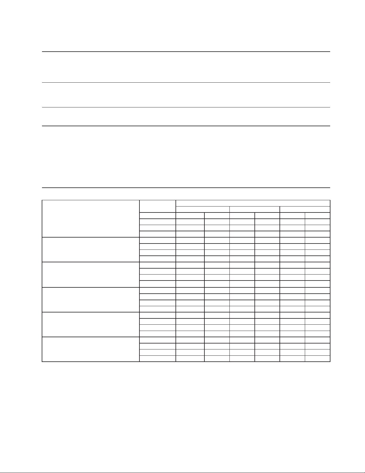
75
9. F-2001MLH
Specification Sheet
AC SUPPLY VOLTAGE 115/60/1
COMPRESSOR N/A
GEAR MOTOR 120 V 5.6 FLA 400W
FAN MOTOR 115 V 0.51 FLA 8W
OTHER 120 V 0.03A
MAXIMUM FUSE SIZE 15 A
MAX. HACR BREAKER (USA ONLY) 15 A
MAX. CIRC. BREAKER (CANADA ONLY) 15 A
MINIMUM CIRCUIT AMPACITY 15 A
ELECTRIC & WATER CONSUMPTION 90/70°F 70/50°F
ELECTRIC W (kWH/100 lbs.) 470 (0.6) 490 (0.5)
WATER gal./24HR (gal./100 lbs.) 207 (12) 258 (12)
SHAPE OF ICE Flake
ICE HARDNESS Approx. 70%, Ice (32/21 (90/70), Conductivity 200 µs/cm)
BIN CONTROL SYSTEM (PRIMARY) Photoelectric Sensor (BC1 (Infrared Sensor))
BIN CONTROL SYSTEM (SECONDARY) Proximity Switch (BC2 (Mechanical))
CONDENSING UNIT Required capacity for ice maker is 11600 BTU/h at discharge
pressure 221 PSIG and suction pressure 22 PSIG with R404A
refrigerant.
Suction pressure needs to be less than 22 PSIG.
REFRIGERANT CONTROL Evaporator Pressure Regulator (EPR)
REFRIGERANT CHARGE R-404A, 3.5 oz. (100g)
Performance Data Sheet
APPROXIMATE Ambient
ICE PRODUCTION Temp. °F (°C)
PER 24 HR. 70 (21) 2280 (921) 1955 (887) 1915 (869)
80 (26) 2010 (851) 1835 (832) 1795 (814)
90 (32) 1760 (798) 1733 (786) 1685 (764)
lbs./DAY ( kg/day) 100 (38) 1650 (748) 1615 (733) 1370 (680)
APPROXIMATE ELECTRIC 70 (21) 490 -- 470 -- 470 --
CONSUMPTION 80 (26) 490 -- 470 -- 470 --
90 (32) 490 -- 470 -- 470 --
watts 100 (38) 490 -- 470 -- 470 --
APPROXIMATE WATER 70 (21) 258 (921) 234 (887) 230 (869)
CONSUMPTION PER 24 HR. 80 (26) 225 (851) 220 (832) 215 (814)
(TOTAL) 90 (32) 211 (798) 207 (785) 202 (764)
gal. / day (m
3
/day)
100 (38) 198 (748) 194 (733) 180 (680)
EVAPORATOR OUTLET TEMP. 70 (21) 12 (-11) 12 (-11) 12 (-11)
°F (°C) 80 (26) 12 (-11) 12 (-11) 12 (-11)
90 (32) 12 (-11) 12 (-11) 14 (-10)
100 (38) 14 (-10) 14 (-10) 14 (-10)
HEAD PRESSURE 70 (21) 190 (18.4) 256 (18.5) 297 (18.6)
PSIG (kg/sq.cmG) 80 (26) 190 (18.4) 256 (18.5) 297 (18.6)
90 (32) 190 (18.4) 256 (18.5) 297 (18.6)
100 (38) 190 (18.4) 256 (18.5) 297 (18.6)
SUCTION PRESSURE 70 (21) 16 (1.8) 21 (1.9) 22 (2.0)
PSIG (kg/sq.cmG) 80 (26) 16 (1.8) 21 (1.9) 22 (2.0)
90 (32) 16 (1.8) 21 (1.9) 22 (2.0)
100 (38) 16 (1.8) 21 (1.9) 22 (2.0)
50 (10) 70 (21) 90 (32)
Water Temp. °F (°C)
ENG.F-013.0.1196
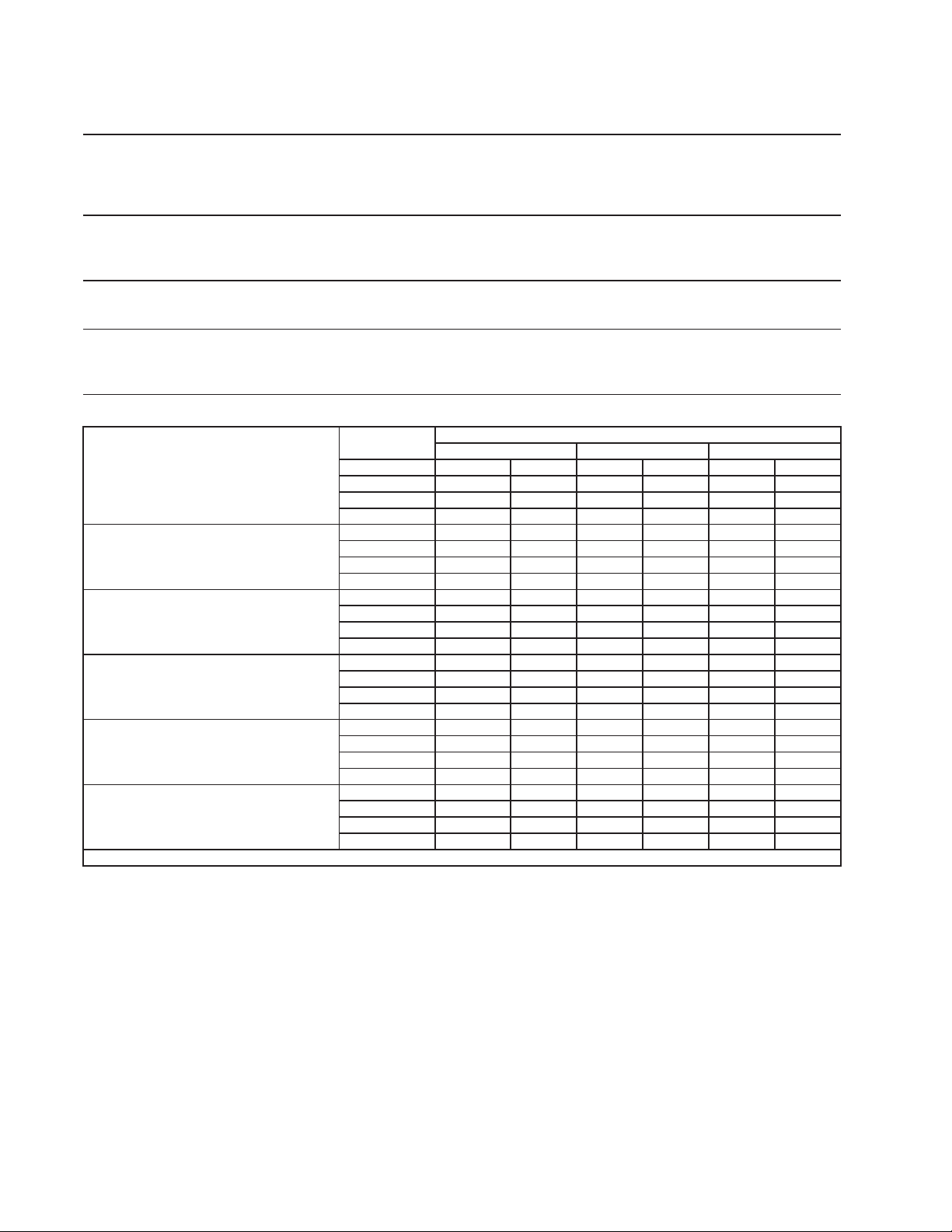
76
10. FD-650MAH-C
Specification Sheet
AC SUPPLY VOLTAGE
115/60/1
COMPRESSOR
115V
7.9 RLA 54.5 LRA
GEAR MOTOR
120 V
2.3 FLA 1/4 HP
FAN MOTOR
115 V
1.0 FLA 1/15 HP
OTHER
115V
0.03A
MAXIMUM FUSE SIZE
20 A
MAX. HACR BREAKER (USA ONLY)
20 A
MAX. CIRC. BREAKER (CANADA ONLY)
20 A
MINIMUM CIRCUIT AMPACITY
20 A
ELECTRIC & WATER CONSUMPTION
90/70°F 70/50°F
ELECTRIC W (kWH/100 lbs.)
1036 (5.35) 274 (3.64)
WATER gal./24HR (gal./100 lbs.)
57 (12.0) 295 (12.0)
SHAPE OF ICE Cubelet
ICE QUALITY
Approx. 86%, Ice (90/70°F, Conductivity 200 μs/cm)
BIN CONTROL SYSTEM Photoelectric Sensor (BC1 (Infrared Sensor))
REFRIGERANT CHARGE R-404A, 12.4 oz. (350g)
Performance Data Sheet
APPROXIMATE Ambient
ICE PRODUCTION Temp. (°F)
PER 24 HR. 70 (21) 650 (295) 627 (284) 593 (269)
80 (26) 576 (261) 523 (237) 490 (222)
90 (32) 490 (222) 474 (215) 439 (199)
lbs./day (kg/day) 100 (38) 423 (192) 418 (189) 380 (172)
APPROXIMATE ELECTRIC 70 (21) 971 -- 980 -- 990 --
CONSUMPTION 80 (26) 999 -- 1008 -- 1017 --
90 (32) 1027 -- 1036 -- 1047 --
watts 100 (38) 1057 -- 1068 -- 1078 --
APPROXIMATE WATER 70 (21) 78 (295) 75 (284) 71 (269)
CONSUMPTION PER 24 HR. 80 (26) 69 (261) 63 (237) 59 (222)
90 (32) 59 (222) 57 (215) 53 (199)
gal./day (l/day)
100 (38) 51 (192) 50 (189) 46 (172)
EVAPORATOR OUTLET TEMP. 70 (21) 19 (-7) 19 (-7) 19 (-7)
°F (°C) 80 (26) 19 (-7) 23 (-5) 23 (-5)
90 (32) 23 (-5) 23 (-5) 25 (-4)
100 (38) 25 (-4) 25 (-4) 25 (-4)
HEAD PRESSURE 70 (21) 250 (17.6) 263 (18.5) 273 (19.2)
PSIG (kg/cm²G) 80 (26) 282 (19.8) 291 (20.4) 300 (21.1)
90 (32) 310 (21.8) 319 (22.4) 327 (23)
100 (38) 337 (23.7) 348 (24.5) 358 (25.2)
SUCTION PRESSURE 70 (21) 41 (2.9) 41 (2.9) 41 (2.9)
PSIG ( kg/cm²G ) 80 (26) 43 (3) 43 (3) 43 (3)
90 (32) 45 (3.2) 45 (3.2) 46 (3.2)
100 (38) 47 (3.3) 47 (3.3) 47 (3.3)
TOTAL HEAT OF REJECTION 6800 BTU/h (AT 90°F /WT 70°F)
90 (32)50 (10) 70 (21)
Water Temp. °F (°C)
ENG F-013.0.1196
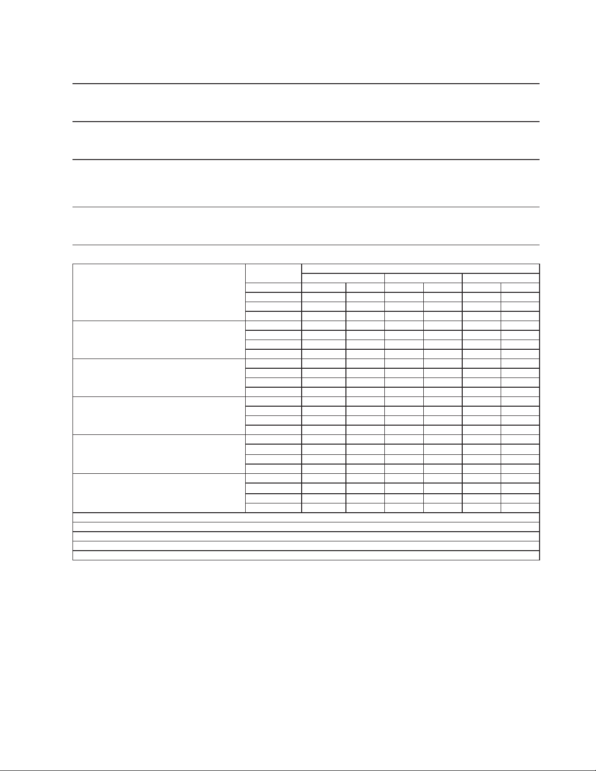
77
11. FD-650MWH-C
Specification Shee
t
AC SUPPLY VOLTAGE 115/60/1
COMPRESSOR 115V 5.5 RLA 50.0 LRA
GEAR MOTOR 120 V 2.3 FLA 1/4 HP
OTHER 115V 0.03A
MAXIMUM FUSE SIZE 20 A
MAX. HACR BREAKER (USA ONLY) 20 A
MAX. CIRC. BREAKER (CANADA ONLY) 20 A
MINIMUM CIRCUIT AMPACITY 20 A
ELECTRIC & WATER CONSUMPTION 90/70 (32/21) 21/10 (70/50)
ELECTRIC: W (kWH/100 lbs.) 949 (3.81) 816 (3.2)
POTABLE WATER: gal./24HR (gal./100 lbs.) 64 (12.0) 74 (12.0)
WATER COOLED CONDENSER 665 (125) 314 (51)
gal./24HR (gal./100lbs)
SHAPE OF ICE Cubelet
ICE QUALITY Approx. 88%, Ice (90/70°F), Conductivity 200 μs/cm)
BIN CONTROL SYSTEM Photoelectric Sensor (BC1 (Infrared Sensor))
REFRIGERANT CHARGE R-404A, 15 oz. (425g)
Performance Data Shee
t
APPROXIMATE Ambient
ICE PRODUCTION Temp. °F (°C)
PER 24 HR. 70 (21) 615 279 601 273 585 265
80 (27) 569 258 554 251 539 245
90 (32) 525 238 532 241 497 226
lbs./day ( kg/day) 100 (38) 484 220 471 214 431 196
APPROXIMATE ELECTRIC 70 (21) 816 -- 835 -- 854 --
CONSUMPTION 80 (27) 873 -- 892 -- 911 --
90 (32) 930 -- 949 -- 920 --
Watts 100 (38) 891 -- 861 -- 832 --
APPROXIMATE WATER 70 (21) 390 1476 638 2414 1261 4773
CONSUMPTION PER 24 HR. 80 (27) 410 1551 680 2574 1356 5134
(TOTAL) 90 (32) 433 1640 703 2660 1461 5528
gal. / day (l/day) 100 (38) 460 1740 778 2946 1667 6308
EVAPORATOR OUTLET TEMP. 70 (21) 8 -13 9 -13 10 -12
°F (°C) 80 (27) 11 -12 8 -13 9 -13
90 (32) 9 -13 10 -12 8 -13
100 (38) 9 -13 9 -13 11 -12
HEAD PRESSURE 70 (21) 272 19 275 19 284 20
PSIG (kg/cm
2
G)
80 (27) 272 19 275 19 284 20
90 (32) 272 19 275 19 284 20
100 (38) 272 19 275 19 284 20
SUCTION PRESSURE 70 (21) 41 3 43 3 45 3
PSIG (kg/cm
2
G)
80 (27) 41 3 43 3 45 3
90 (32) 41 3 43 3 45 3
100 (38) 41 3 43 3 45 3
264 gal/h (AT 90°F/WT 70°F)
Less than 7 PSIG
74.5 cu in
4500 BTU/h (AT 90°F/WT 70°F)
800 BTU/h (AT 90°F/WT 70°F)
50 (10) 70 (21) 90 (32)
Water Temp. °F (°C)
PRESSURE DROP OF COOLING WATER LINE
CONDENSER VOLUME
HEAT OF REJECTION FROM CONDENSER
HEAT OF REJECTION FROM COMPRESSOR
WATER FLOW FOR CONDENSER
ENG F-013.0.1196
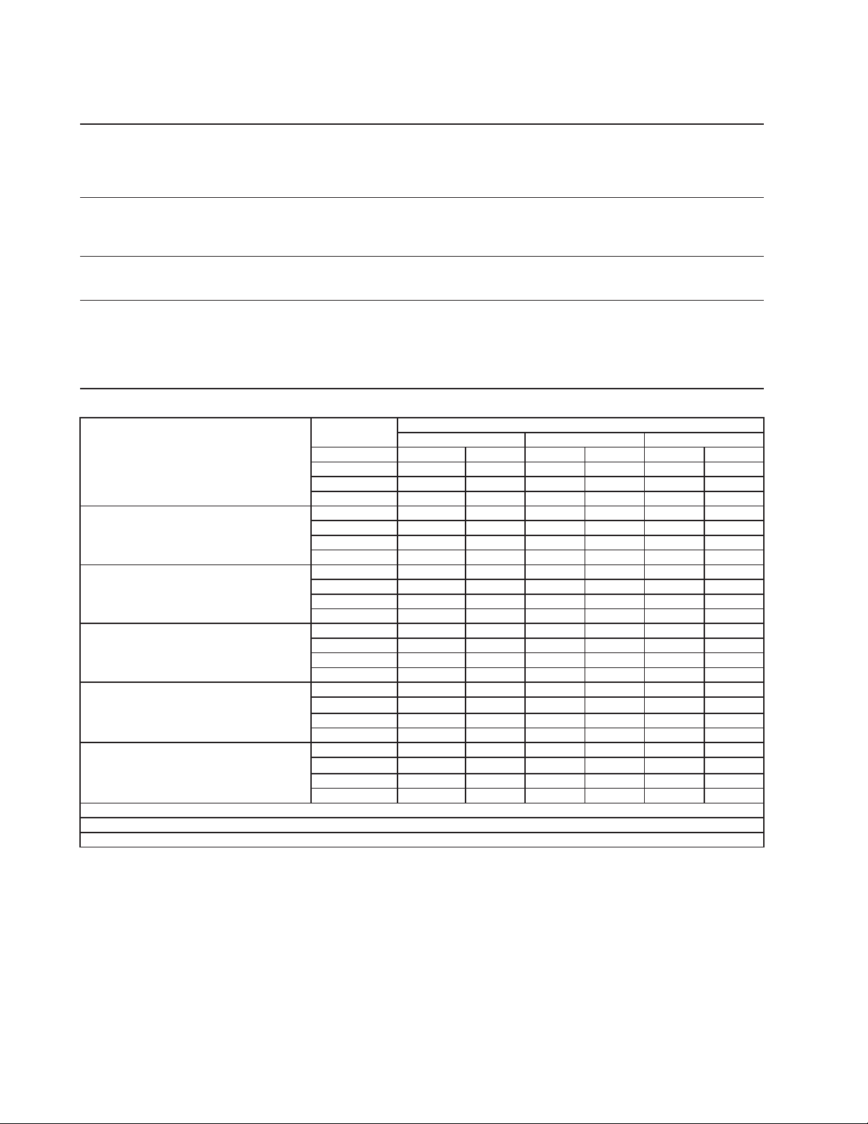
78
12. FD-650MRH-C
Specification Sheet
AC SUPPLY VOLTAGE 115/60/1
COMPRESSOR 115V 5.5 RLA 50.0 LRA
GEAR MOTOR 120 V 2.3 FLA 1/4 HP
FAN MOTOR 120 V 3A MAX
OTHER 115V 0.03A
MAXIMUM FUSE SIZE 20 A
MAX. HACR BREAKER (USA ONLY) 20 A
MAX. CIRC. BREAKER (CANADA ONLY) 20 A
MINIMUM CIRCUIT AMPACITY 20 A
ELECTRIC & WATER CONSUMPTION 90/70 (32/21) 21/10 (70/50)
ELECTRIC: W (kWH/100 lbs.) 949 (4.75) 889 (3.75)
WATER: gal./24HR (gal./100 lbs.) 57 (12.0) 71 (12.0)
SHAPE OF ICE Cubelet
ICE QUALITY Approx. 88%, Ice (90/70°F), Conductivity 200 μs/cm)
BIN CONTROL SYSTEM Photoelectric Sensor (BC1 (Infrared Sensor))
CONDENSER
Air-cooled Remote Condenser unit URC-5F Recommended
REFRIGERANT CHARGE R-404A, 4 lb. 1.2 oz. (1850g)
(Ice Maker: 2 lb. 3.2 oz. (1000g) Cond. Unit: 1 lb. 14 oz. (850g)
Performance Data Sheet
APPROXIMATE Ambient
ICE PRODUCTION Temp. °F (°C)
PER 24 HR. 70 (21) 590 268 571 259 551 250
80 (27) 531 241 513 233 495 224
90 (32) 477 216 476 216 444 201
lbs./day ( kg/day) 100 (38) 428 194 413 187 382 173
APPROXIMATE ELECTRIC 70 (21) 889 -- 898 -- 906 --
CONSUMPTION 80 (27) 915 -- 923 -- 932 --
90 (32) 940 -- 949 -- 951 --
Watts 100 (38) 952 -- 954 -- 955 --
APPROXIMATE WATER 70 (21) 71 268 69 259 66 250
CONSUMPTION PER 24 HR. 80 (27) 64 242 62 233 59 225
(TOTAL) 90 (32) 57 217 57 216 53 202
gal. / day (l/day) 100 (38) 51 195 50 188 46 174
EVAPORATOR OUTLET TEMP. 70 (21) 10 -12 11 -12 12 -11
°F (°C) 80 (27) 13 -11 10 -12 12 -11
90 (32) 12 -11 12 -11 10 -12
100 (38) 11 -12 11 -11 13 -10
HEAD PRESSURE 70 (21) 204 14 245 17 279 20
PSIG (kg/cm
2
G)
80 (27) 204 14 245 17 279 20
90 (32) 204 14 245 17 279 20
100 (38) 204 14 245 17 279 20
SUCTION PRESSURE 70 (21) 44
3463473
PSIG (kg/cm
2
G)
80 (27) 44 3 46 3 47 3
90 (32) 44 3 46
3473
100 (38) 44 3 46 3 47 3
74.5 cu in
4900 BTU/h (AT 90°F / WT 70°F)
800 BTU/h (AT 90°F / WT 70°F)
HEAT OF REJECTION FROM CONDENSER
HEAT OF REJECTION FROM COMPRESSOR
CONDENSER VOLUME
Water Temp. °F (°C)
50 (10) 70 (21) 90 (32)
ENG F-013.0.1196
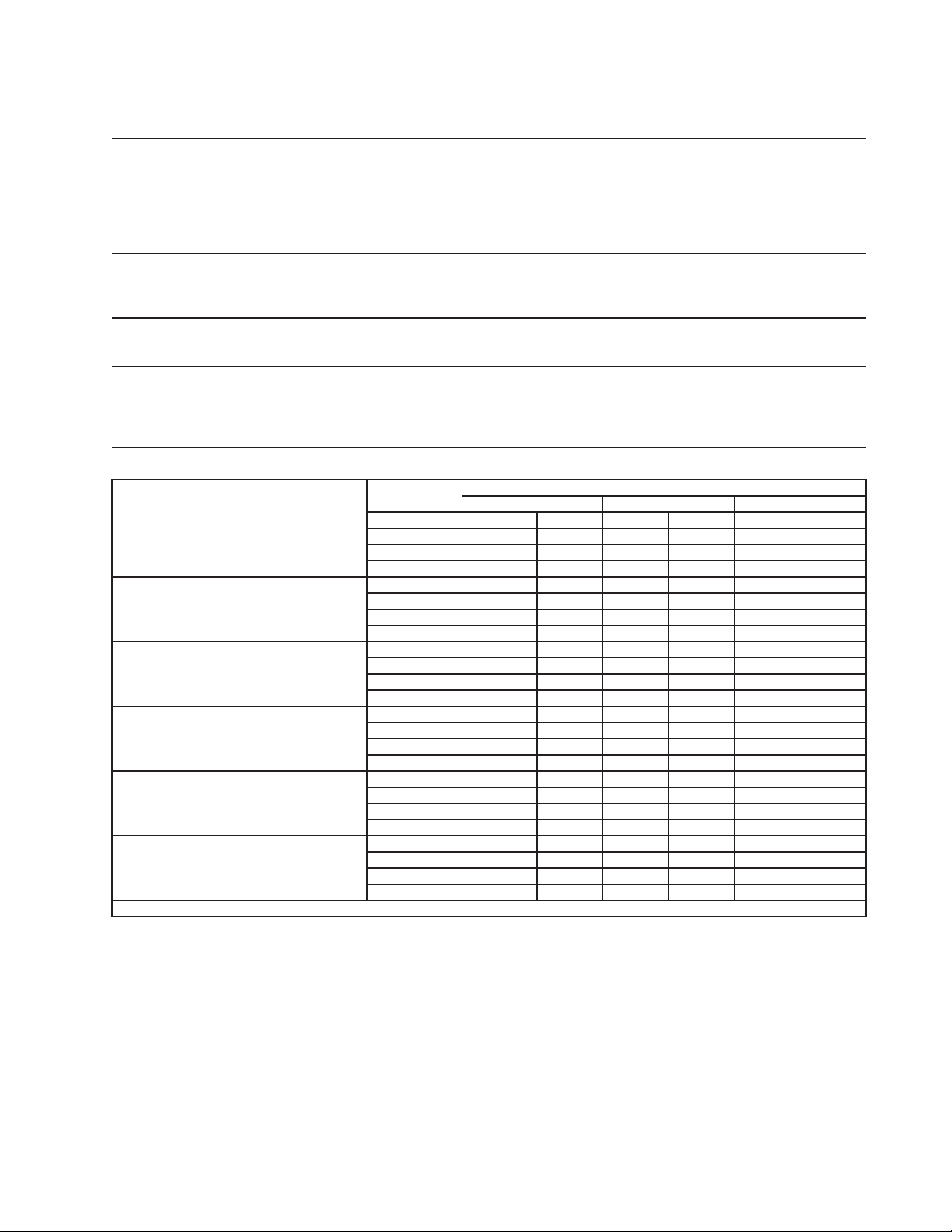
79
Specification Sheet
AC SUPPLY VOLTAGE 208-230/60/1 (3 wire with neutral)
4.2 RLA 34 LRA 5.9 RLA 46 LRA
GEAR MOTOR 120 V 3 FLA 1/4 HP
FAN MOTOR 115 V 0.85FLA 1/15 HP
OTHER 120 V 0.03A
MAXIMUM FUSE SIZE 15 A
MAX. HACR BREAKER (USA ONLY) 15 A
MAX. CIRC. BREAKER (CANADA ONLY) 15 A
MINIMUM CIRCUIT AMPACITY 15 A
ELECTRIC & WATER CONSUMPTION 90/70°F 70/50°F
ELECTRIC W (kWH/100 lbs.) 1390 (4.8) 1320 (3.4)
WATER gal./24HR (gal./100 lbs.) 86 (12) 113 (12)
SHAPE OF ICE Cubelet
ICE QUALITY Approx. 80%, Ice (90/70°F, Conductivity 200 μs/cm)
BIN CONTROL SYSTEM (PRIMARY) Photoelectric Sensor (BC1 (Infrared Sensor))
BIN CONTROL SYSTEM (SECONDARY) Proximity Switch (BC2 (Mechanical))
REFRIGERANT CHARGE R-404A
Performance Data Sheet
APPROXIMATE Ambient
ICE PRODUCTION Temp. °F (°C)
PER 24 HR. 70 (21) 940
(427)
890
(405)
855
(389)
80 (26) 820
(373)
790
(358)
755
(344)
90 (32) 725
(330)
695
(317)
670
(304)
lbs./day (kg/day) 100 (38) 640
(292)
615
(280)
580
(265)
APPROXIMATE ELECTRIC 70 (21) 1319 -- 1329 -- 1339 --
CONSUMPTION 80 (26) 1349 -- 1359 -- 1369 --
90 (32) 1379 -- 1389 -- 1393 --
watts 100 (38) 1397 -- 1400 -- 1404 --
APPROXIMATE WATER 70 (21) 113
(427)
107
(405)
103
(389)
CONSUMPTION PER 24 HR. 80 (26) 99
(373)
95
(358)
91
(344)
90 (32) 87
(330)
84
(317)
80
(304)
gal./day (l/day)
100 (38) 77
(292)
74
(280)
70
(265)
EVAPORATOR OUTLET TEMP. 70 (21) 12 (-11) 12 (-11) 12 (-11)
°F (°C) 80 (26) 12 (-11) 14
(-10)
14
(-10)
90 (32) 14
(-10)
14
(-10)
17 (-9)
100 (38) 17 (-9) 17 (-9) 17 (-9)
HEAD PRESSURE 70 (21) 204 (14.3) 204 (14.3) 204 (14.3)
PSIG (kg/cm²G) 80 (26) 236 (16.6) 236 (16.6) 236 (16.6)
90 (32) 269
(18.9)
269
(18.9)
269
(18.9)
100 (38) 304 (21.4) 304 (21.4) 304 (21.4)
SUCTION PRESSURE 70 (21) 31
(2.2)
31 (2.2) 31 (2.2)
PSIG ( kg/cm²G ) 80 (26) 34 (2.4) 34 (2.4) 34
(2.4)
90 (32) 36
(2.5)
36
(2.5)
36
(2.5)
100 (38) 39
(2.7)
39
(2.7)
39
(2.7)
TOTAL HEAT OF REJECTION
8800 BTU/h (AT 90°F /WT 70°F)
1 lb. 12 oz. (800g) 2 lb. 4.1 oz. (1035g)
50 (10) 70 (21) 90 (32)
Water Temp. °F (°C)
COMPRESSOR 240 V
Aux. Code C-0
and Earlier
Aux. Code C-1
and Later
ENG F-013.0.1196
13. FD-1001MAH-C
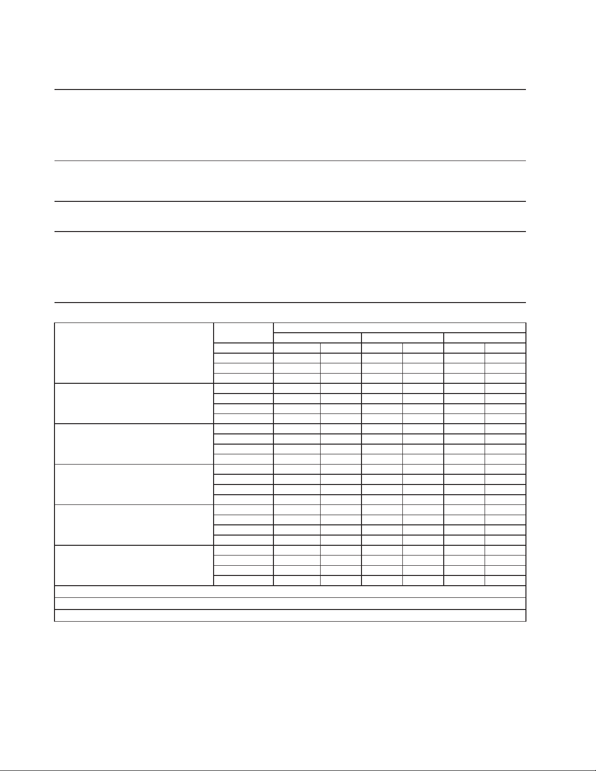
80
Specification Sheet
AC SUPPLY VOLTAGE 208-230/60/1 (3 wire with neutral)
4.2 RLA 34 LRA 5.9 RLA 46 LRA
GEAR MOTOR 120 V 3 FLA 1/4 HP
FAN MOTOR REMOTE 115 V 3A MAX
OTHER 120 V 0.03A
MAXIMUM FUSE SIZE 15 A
MAX. HACR BREAKER (USA ONLY) 15 A
MAX. CIRC. BREAKER (CANADA ONLY) 15 A
MINIMUM CIRCUIT AMPACITY 15 A
ELECTRIC & WATER CONSUMPTION 90/70°F 70/50°F
ELECTRIC W (kWH/100 lbs.) 1449 (4.8) 1401 (3.6)
WATER gal./24HR (gal./100 lbs.) 86 (12) 112 (12)
SHAPE OF ICE Cubelet
ICE QUALITY Approx. 80%, Ice (90/70°F, Conductivity 200 µs/cm)
BIN CONTROL SYSTEM (PRIMARY) Photoelectric Sensor (BC1 (Infrared Sensor))
BIN CONTROL SYSTEM (SECONDARY) Proximity Switch (BC2 (Mechanical))
CONDENSER Air-cooled Remote Condenser unit URC-5F Recommended
REFRIGERANT CHARGE R-404A, 4 lb. 1 oz. (1850g)
(Ice Maker: 2 lb. 3 oz., Cond. Unit: 1 lb. 14 oz. )
Performance Data Sheet
APPROXIMATE Ambient
ICE PRODUCTION Temp. °F (°C)
PER 24 HR. 70 (21) 930 (423) 895
(406)
860
(390)
80 (26) 825 (375) 790
(360)
760
(345)
90 (32) 730
(332)
720
(326)
670
(306)
lbs./day (kg/day) 100 (38) 645
(294)
620
(282)
580
(263)
APPROXIMATE ELECTRIC 70 (21) 1401 -- 1408 -- 1415 --
CONSUMPTION 80 (26) 1422 -- 1428 -- 1435 --
90 (32) 1442 -- 1449 -- 1444 --
watts 100 (38) 1440 -- 1435 -- 1430 --
APPROXIMATE WATER 70 (21) 112
(423)
108
(406)
103
(390)
CONSUMPTION PER 24 HR. 80 (26) 99
(375)
95
(360)
91
(345)
90 (32) 88
(332)
86
(326)
81
(306)
gal./day (l/day)
100 (38) 78
(294)
75
(282)
70
(263)
EVAPORATOR OUTLET TEMP. 70 (21) 5 (-15) 5 (-15) 5 (-15)
°F (°C) 80 (26) 5 (-15) 9
(-13)
9
(-13)
90 (32) 9
(-13)
9
(-13)
12
(-11)
100 (38) 12
(-11)
12
(-11)
12
(-11)
HEAD PRESSURE 70 (21) 205
(14.4)
205
(14.4)
205
(14.4)
PSIG (kg/cm²G) 80 (26) 234 (16.5) 234 (16.5) 234 (16.5)
90 (32) 264
(18.6)
264
(18.6)
264
(18.6)
100 (38) 301 (21.1) 301 (21.1) 301 (21.1)
SUCTION PRESSURE 70 (21) 33
(2.3)
33 (2.3) 33 (2.3)
PSIG ( kg/cm²G ) 80 (26) 35 (2.4) 35 (2.4) 35 (2.4)
90 (32) 36
(2.6)
36
(2.6)
36
(2.6)
100 (38) 39
(2.7)
39
(2.7)
39
(2.7)
CONDENSERVOLUME 74.5cuin
HEATOFREJECTIONFROMCONDENSER 8900BTU/h(AT90°F/WT70°F)
HEATOFREJECTIONFROMCOMPRESSOR 1400BTU/h(AT90°F/WT70°F)
50 (10) 70 (21) 90 (32)
Water Temp. °F (°C)
COMPRESSOR 240 V
Aux. Code C-0
and Earlier
Aux. Code C-1
and Later
ENG F-013.0.1196
14. FD-1001MRH-C
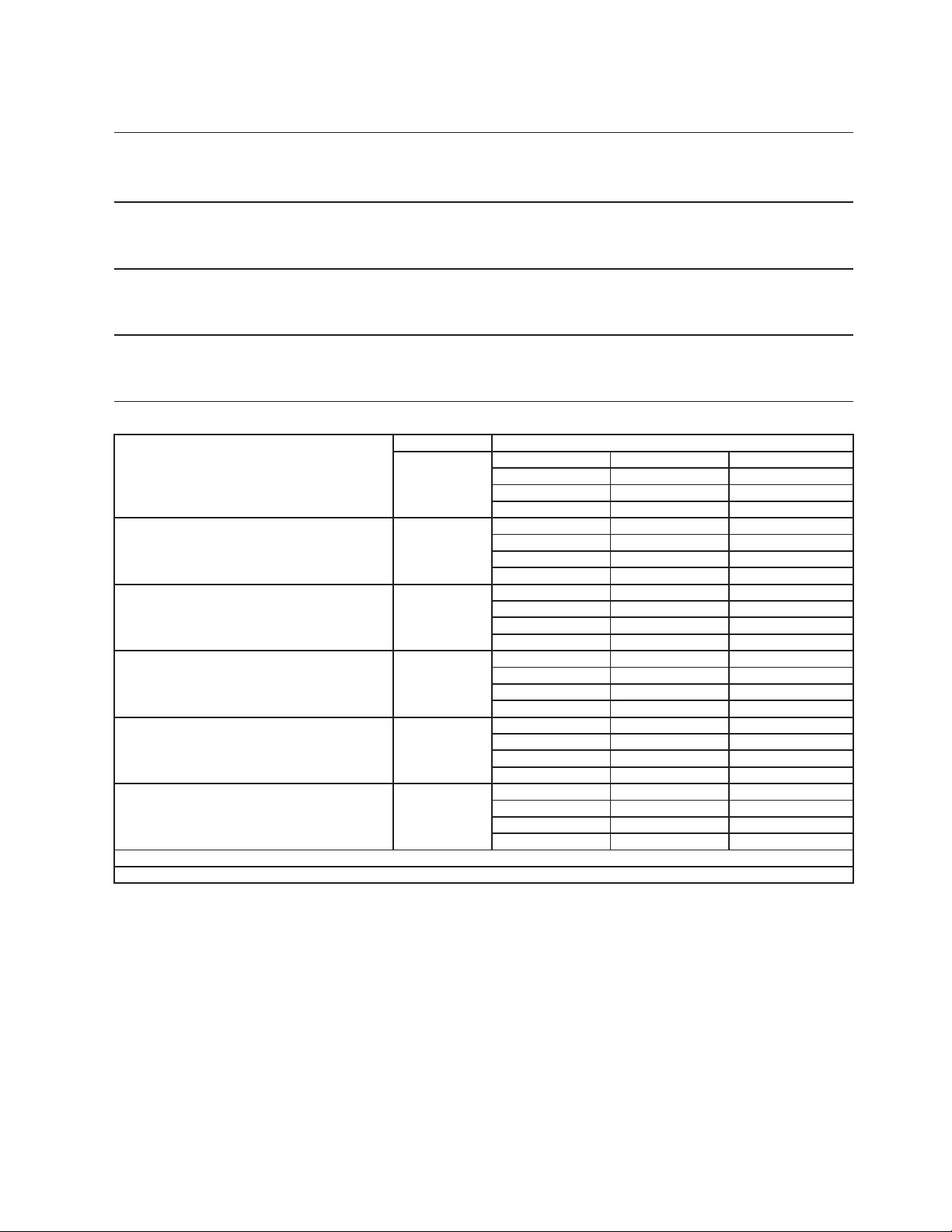
81
15a. F-450MAJ
S
p
ecification Shee
t
AC SUPPLY VOLTAGE 115/60/1
COMPRESSOR 115/60/1 8.4 RLA 50 LRA
GEAR MOTOR 115 V 2.4 FLA 1/4 HP
OTHER 115 V 0.03 A
MAXIMUM FUSE SIZE 20
A
MAX. HACR BREAKER
(
USA ONLY
)
20
A
MAX. CIRC. BREAKER
(
CANADA ONLY
)
20
A
MINIMUM CIRCUIT AMPACITY 20
A
ELECTRIC & WATER CONSUMPTION 90/70°F 70/50°F
ELECTRIC W
(
kWH/100 lbs.
)
789
(
4.94
)
760
(
3.71
)
POTABLE WATER 47
(
12.0
)
59
(
12.0
)
g
al./24HR
(g
al./100 lbs.
)
SHAPE OF ICE Flake
ICE HARDNESS A
pp
rox. 68%, Ice
(
90/70°F, Conductivit
y
200
µ
s/cm
)
BIN CONTROL SYSTEM Photoelectric Senso
r
REFRIGERANT CHARGE R404A, 0 lb. 15.2 oz.
(
430
g)
Performance Data Shee
t
APPROXIMATE Ambien
t
PER 24 HR.
70 (21)
492
(
223
)
486
(
220
)
467
(
212
)
80 (26)
449
(
204
)
432
(
196
)
415
(
188
)
90 (32)
399
(
181
)
395
(
179
)
369
(
167
)
lbs./da
y (
k
g
/da
y)
100 (38)
355
(
161
)
341
(
155
)
315
(
143
)
APPROXIMATE ELECTRIC
70 (21)
760
-- 764 -- 769 --
CONSUMPTION
80 (26)
773 -- 777 -- 781 --
90 (32)
785 --
789
-- 796 --
watts
100 (38)
802 -- 808 --
814
--
APPROXIMATE WATER
70 (21)
59
(
224
)
58
(
221
)
56
(
212
)
CONSUMPTION PER 24 HR.
80 (26)
54
(
204
)
52
(
196
)
50
(
189
)
(
TOTAL
)
90 (32)
48
(
181
)
47
(
180
)
44
(
168
)
g
al. / da
y (
l/da
y)
100 (38)
43
(
161
)
41
(
155
)
38
(
143
)
EVAPORATOR OUTLET TEMP.
70 (21)
0
(
(
-18
)
)
1
(
(
-17
)
)
3
(
(
-16
)
)
°F
(
°C
)
80 (26)
4
(
(
-15
)
)
6
(
(
-15
)
)
7
(
(
-14
)
)
90 (32)
9
(
(
-13
)
)
10
(
(
-12
)
)
9
(
(
-13
)
)
100 (38)
7
(
(
-14
)
)
6
(
(
-15
)
)
4
(
(
-15
)
)
HEAD PRESSURE
70 (21)
191
(
13.4
)
199
(
14.0
)
207
(
14.6
)
80 (26)
215
(
15.1
)
224
(
15.7
)
232
(
16.3
)
90 (32)
240
(
16.9
)
248
(
17.4
)
259
(
18.2
)
PSIG
(
k
g
/cm
2
G
)
100 (38)
270
(
19.0
)
281
(
19.7
)
291
(
20.5
)
SUCTION PRESSURE
70 (21)
25
(
1.8
)
26
(
1.8
)
26
(
1.8
)
PSIG
(
k
g
/cm
2
G
)
80 (26)
27
(
1.9
)
27
(
1.9
)
28
(
2.0
)
90 (32)
28
(
2.0
)
29
(
2.0
)
30
(
2.1
)
100 (38)
30
(
2.1
)
31
(
2.2
)
31
(
2.2
)
BTU/h
(
AT 90°F / WT 70°F
)
BTU/h
(
AT 90°F / WT 70°F
)
HEAT OF REJECTION FROM CONDENSER 4,700
HEAT OF REJECTION FROM COMPRESSOR 800
Water Temp. °F (°C)
ENG F-013.0.1196
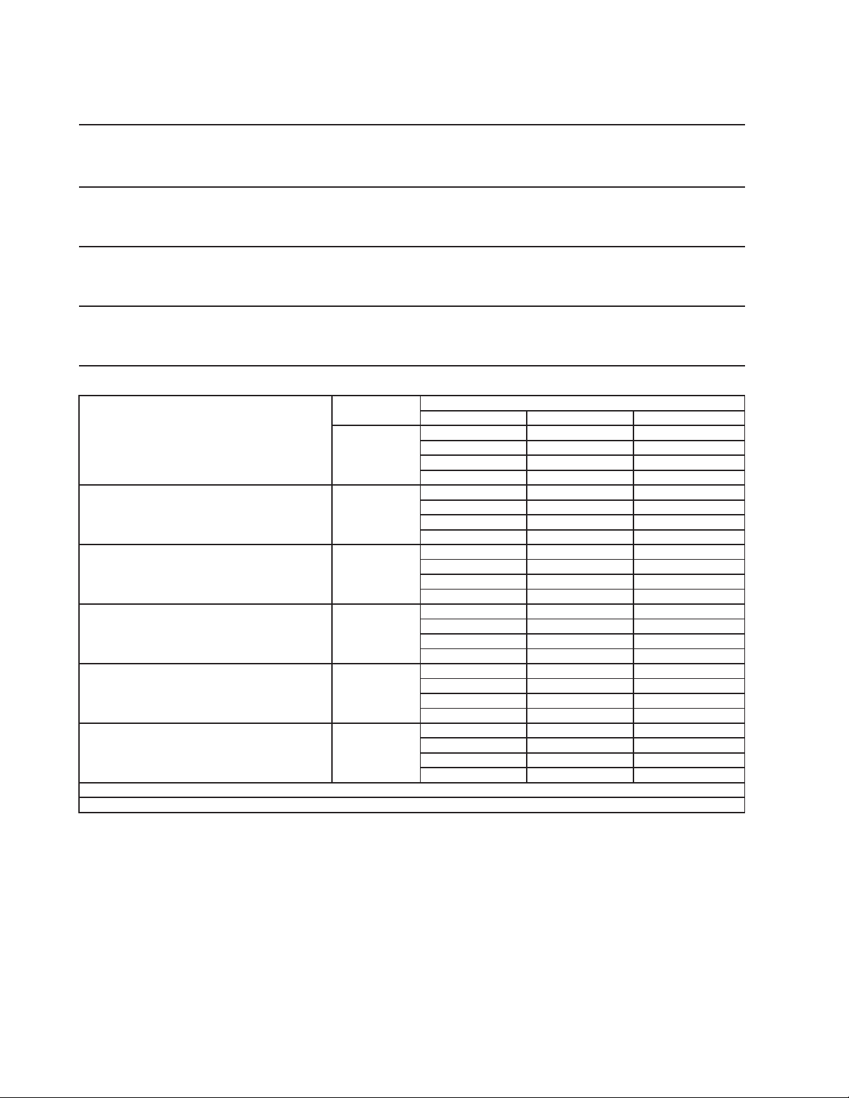
82
15b. F-450MAJ-C
S
p
ecification Shee
t
AC SUPPLY VOLTAGE 115/60/1
COMPRESSOR 115/60/1 8.4 RLA 50 LRA
GEAR MOTOR 115 V 2.4 FLA 1/4 HP
OTHER 115 V 0.03 A
MAXIMUM FUSE SIZE 15
A
MAX. HACR BREAKER
(
USA ONLY
)
15
A
MAX. CIRC. BREAKER
(
CANADA ONLY
)
15
A
MINIMUM CIRCUIT AMPACITY 15
A
ELECTRIC & WATER CONSUMPTION 90/70°F 70/50°F
ELECTRIC W
(
kWH/100 lbs.
)
813
(
6.10
)
795
(
4.63
)
POTABLE WATER 38
(
12.0
)
49
(
12.0
)
g
al./24HR
(g
al./100 lbs.
)
SHAPE OF ICE Cubele
t
ICE HARDNESS A
pp
rox. 80.8%, Ice
(
90/70°F, Conductivit
y
200
µ
s/cm
)
BIN CONTROL SYSTEM Photoelectric Senso
r
REFRIGERANT CHARGE R404A, 0 lb. 15.2 oz. (430g
)
Performance Data Shee
t
APPROXIMATE Ambien
t
ICE PRODUCTION Tem
p
. °F
(
°C
)
PER 24 HR.
70 (21)
412
(
187
)
400
(
181
)
384
(
174
)
80 (26)
369
(
168
)
355
(
161
)
341
(
155
)
90 (32)
328
(
149
)
316
(
143
)
303
(
138
)
lbs./da
y (
k
g
/da
y)
100 (38)
292
(
132
)
280
(
127
)
267
(
121
)
APPROXIMATE ELECTRIC
70 (21)
795
-- 798 -- 800 --
CONSUMPTION
80 (26)
803 -- 805 -- 808 --
90 (32)
811 --
813
-- 825 --
watts
100 (38)
837 -- 848 --
860
--
APPROXIMATE WATER
70 (21)
49
(
187
)
48
(
182
)
46
(
175
)
CONSUMPTION PER 24 HR.
80 (26)
44
(
168
)
43
(
161
)
41
(
155
)
(
TOTAL
)
90 (32)
39
(
149
)
38
(
144
)
36
(
138
)
g
al. / da
y (
l/da
y)
100 (38)
35
(
133
)
34
(
127
)
32
(
121
)
EVAPORATOR OUTLET TEMP.
70 (21)
5
(
(
-15
)
)
5
(
(
-15
)
)
6
(
(
-15
)
)
°F
(
°C
)
80 (26)
6
(
(
-14
)
)
7
(
(
-14
)
)
7
(
(
-14
)
)
90 (32)
8
(
(
-13
)
)
8
(
(
-13
)
)
10
(
(
-12
)
)
100 (38)
12
(
(
-11
)
)
14
(
(
-10
)
)
16
(
(
-9
)
)
HEAD PRESSURE
70 (21)
194
(
13.6
)
202
(
14.2
)
210
(
14.8
)
80 (26)
219
(
15.4
)
227
(
16.0
)
235
(
16.5
)
90 (32)
244
(
17.1
)
252
(
17.7
)
261
(
18.3
)
PSIG
(
k
g
/cm
2
G
)
100 (38)
269
(
18.9
)
278
(
19.5
)
286
(
20.1
)
SUCTION PRESSURE
70 (21)
28
(
2.0
)
28
(
2.0
)
29
(
2.0
)
PSIG
(
k
g
/cm
2
G
)
80 (26)
29
(
2.0
)
29
(
2.0
)
29
(
2.1
)
90 (32)
30
(
2.1
)
30
(
2.1
)
33
(
2.3
)
100 (38)
36
(
2.5
)
38
(
2.7
)
41
(
2.9
)
BTU/h
(
AT 90°F / WT 70°F
)
BTU/h
(
AT 90°F / WT 70°F
)
HEAT OF REJECTION FROM CONDENSER 4,700
HEAT OF REJECTION FROM COMPRESSOR 800
Water Temp. °F (°C)
50 (10) 70 (21) 90 (32)
ENG F-013.0.1196
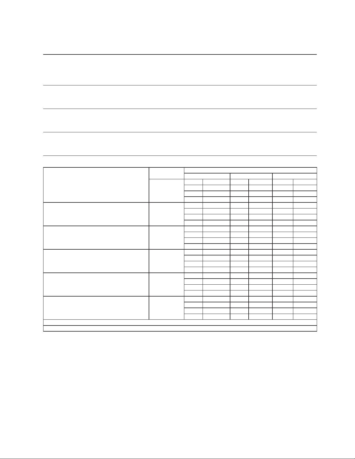
83
16a. F-801MAJ
S
p
ecification Sheet
A
C SUPPLY VOLTAGE 115/60/1
COMPRESSOR 115/60/1 7.5 RLA 54.5 LRA
GEAR MOTOR 115 V 3.0 FLA 1/4 HP
FAN MOTOR 115 V 1.0 FLA 1/15 HP
OTHER 115 V 0.03 A
MAXIMUM FUSE SIZE 15
A
MAX. HACR BREAKER
(
USA ONLY
)
15
A
MAX. CIRC. BREAKER
(
CANADA ONLY
)
15
A
MINIMUM CIRCUIT AMPACIT
Y
15
A
ELECTRIC & WATER CONSUMPTION 90/70°F
70/50°F
ELECTRIC W
(
kWH/100 lbs.
)
1078 (4.50) 1022 (3.27)
POTABLE WATER
68 (12.0) 90 (12.0)
g
al./24HR
(g
al./100 lbs.
)
SHAPE OF ICE Flake
ICE HARDNESS
App
rox. 79.4%, Ice
(
90/70°F, Conductivit
y
200
µ
s/cm
)
BIN CONTROL SYSTEM Photoelectric Senso
r
REFRIGERANT CHARGE R404A, 1 lb. 12 oz. (793g
)
Performance Data Shee
t
A
PPROXIMATE
A
mbien
t
ICE PRODUCTION Tem
p
. °F
(
°C
)
PER 24 HR.
70 (21)
751
(
0
)
730
(
331
)
699
(
317
)
80 (26)
669
(
303
)
640
(
290
)
612
(
278
)
90 (32)
586
(
266
)
566
(
257
)
537
(
243
)
lbs./da
y (
k
g
/da
y)
100 (38)
514
(
233
)
492
(
223
)
462
(
210
)
A
PPROXIMATE ELECTRIC
70 (21)
1022
-
-
1030 -
-
1038 -
-
CONSUMPTION
80 (26)
1046 -
-
1054 -
-
1062 -
-
90 (32)
1070 -
-
1078
-
-
1089 -
-
watts
100 (38)
1101 -
-
1113 -
-
1124
-
-
A
PPROXIMATE WATER
70 (21)
90
(
341
)
88
(
332
)
84
(
317
)
CONSUMPTION PER 24 HR.
80 (26)
80
(
304
)
77
(
291
)
74
(
278
)
(
TOTAL
)
90 (32)
70
(
266
)
68
(
257
)
64
(
244
)
g
al. / da
y (
l/da
y)
100 (38)
62
(
233
)
59
(
223
)
55
(
210
)
EVAPORATOR OUTLET TEMP.
70 (21)
13
(
(
-11
)
)
13
(
(
-11
)
)
13
(
(
-10
)
)
°F
(
°C
)
80 (26)
14
(
(
-10
)
)
14
(
(
-10
)
)
14
(
(
-10
)
)
90 (32)
14
(
(
-10
)
)
15
(
(
-10
)
)
15
(
(
-9
)
)
100 (38)
16
(
(
-9
)
)
17
(
(
-8
)
)
17
(
(
-8
)
)
HEAD PRESSURE
70 (21)
202
(
14.2
)
210
(
14.8
)
219
(
15.4
)
80 (26)
227
(
16.0
)
236
(
16.6
)
245
(
17.2
)
90 (32)
253
(
17.8
)
262
(
18.4
)
273
(
19.2
)
PSIG
(
k
g
/cm
2
G
)
100 (38)
284
(
19.9
)
294
(
20.7
)
305
(
21.5
)
SUCTION PRESSURE
70 (21)
39
(
2.7
)
39
(
2.8
)
40
(
2.8
)
PSIG
(
k
g
/cm
2
G
)
80 (26)
40
(
2.8
)
40
(
2.8
)
41
(
2.8
)
90 (32)
41
(
2.9
)
41
(
2.9
)
42
(
3.0
)
100 (38)
43
(
3.0
)
44
(
3.1
)
44
(
3.1
)
BTU/h
(
AT 90°F / WT 70°F
)
BTU/h
(
AT 90°F / WT 70°F
)
HEAT OF REJECTION FROM COMPRESSOR 900
Water Temp. °F (°C)
50 (10) 70 (21) 90 (32)
HEAT OF REJECTION FROM CONDENSE
R
5,900
ENG F-013.0.1196
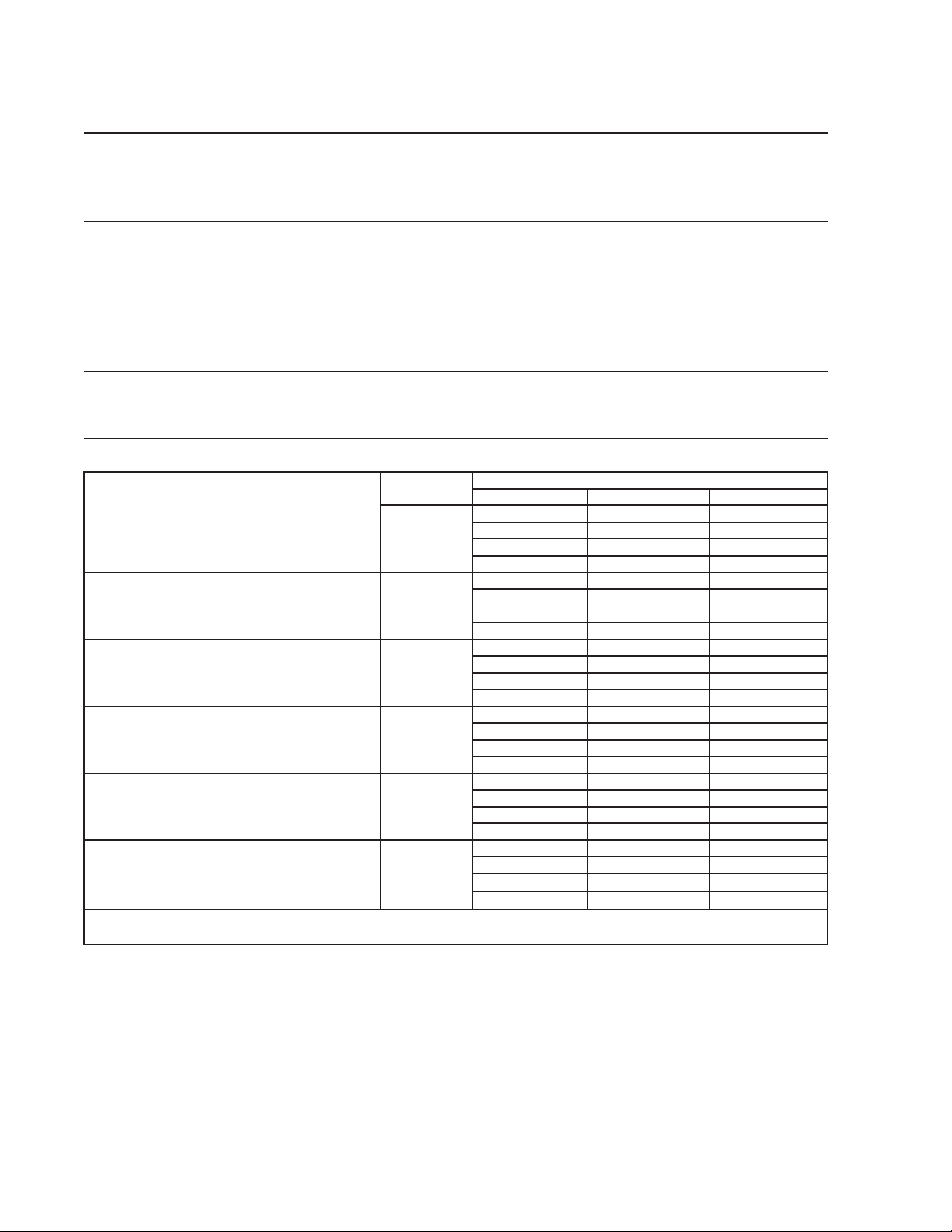
84
16b. F-801MAJ-C
S
p
ecification Shee
t
AC SUPPLY VOLTAGE 115/60/1
COMPRESSOR 115/60/1 7.5 RLA 54.5 LRA
GEAR MOTOR 115 V 3.0 FLA 200W
FAN MOTOR 115 V 1.0 FLA 1/15 HP
OTHER 115 V 0.03 A
MAXIMUM FUSE SIZE 15
A
MAX. HACR BREAKER
(
USA ONLY
)
15
A
MAX. CIRC. BREAKER
(
CANADA ONLY
)
15
A
MINIMUM CIRCUIT AMPACITY 15
A
ELECTRIC & WATER CONSUMPTION 90/70°F 70/50°F
ELECTRIC W (kWH/100 lbs.) 1104(5.00
)
1078(3.75
)
POTABLE WATER 64(12.0) 83(12.0)
WATER-COOLED CONDENSER
gal./24HR (gal./100 lbs.
)
SHAPE OF ICE Cubele
t
ICE HARDNESS A
pp
rox. 86.6%, Ice
(
90/70°F, Conductivit
y
200
µ
s/cm
)
BIN CONTROL SYSTEM Photoelectric Senso
r
REFRIGERANT CHARGE R404A, 1 lb. 12 oz.
(
790
g)
Performance Data Shee
t
APPROXIMATE Ambien
t
ICE PRODUCTION Tem
p
. °F
(
°C
)
PER 24 HR.
70 (21)
690
(
313
)
670
(
304
)
645
(
292
)
80 (26)
620
(
281
)
596
(
270
)
574
(
260
)
90 (32)
552
(
250
)
532
(
241
)
510
(
231
)
lbs./da
y (
k
g
/da
y)
100 (38)
491
(
223
)
472
(
214
)
450
(
204
)
APPROXIMATE ELECTRIC
70 (21)
1078
-- 1081 -- 1085 --
CONSUMPTION
80 (26)
1089 -- 1093 -- 1096 --
90 (32)
1100 --
110
4
-- 1117 --
watts
100 (38)
1130 -- 1143 --
1156
--
APPROXIMATE WATER
70 (21)
83
(
314
)
80
(
305
)
77
(
293
)
CONSUMPTION PER 24 HR.
80 (26)
74
(
282
)
72
(
271
)
69
(
261
)
(
TOTAL
)
90 (32)
66
(
251
)
64
(
242
)
61
(
232
)
g
al. / da
y (
l/da
y)
100 (38)
59
(
223
)
57
(
215
)
54
(
205
)
EVAPORATOR OUTLET TEMP.
70 (21)
16
(
(
-9
)
)
16
(
(
-9
)
)
16
(
(
-9
)
)
°F
(
°C
)
80 (26)
17
(
(
-9
)
)
17
(
(
-8
)
)
17
(
(
-8
)
)
90 (32)
17
(
(
-8
)
)
17
(
(
-8
)
)
18
(
(
-8
)
)
100 (38)
19
(
(
-7
)
)
19
(
(
-7
)
)
20
(
(
-7
)
)
HEAD PRESSURE
70 (21)
202
(
14.2
)
210
(
14.8
)
219
(
15.4
)
80 (26)
228
(
16.0
)
237
(
16.6
)
245
(
17.2
)
90 (32)
254
(
17.9
)
263
(
18.5
)
273
(
19.2
)
PSIG
(
k
g
/cm
2
G
)
100 (38)
282
(
19.8
)
292
(
20.5
)
302
(
21.2
)
SUCTION PRESSURE
70 (21)
39
(
2.7
)
39
(
2.8
)
40
(
2.8
)
PSIG
(
k
g
/cm
2
G
)
80 (26)
40
(
2.8
)
41
(
2.9
)
41
(
2.9
)
90 (32)
42 ( 2.9 )
42
( 3.0 ) 43 ( 3.0 )
100 (38)
43 ( 3.0 ) 44 ( 3.1 )
44
( 3.1 )
BTU/h (AT 90°F / WT 70°F)
BTU/h (AT 90°F / WT 70°F)
HEAT OF REJECTION FROM COMPRESSOR 500
HEAT OF REJECTION FROM CONDENSER 5,000
Water Temp. °F (°C)
50 (10) 70 (21) 90 (32)
ENG F-013.0.1196
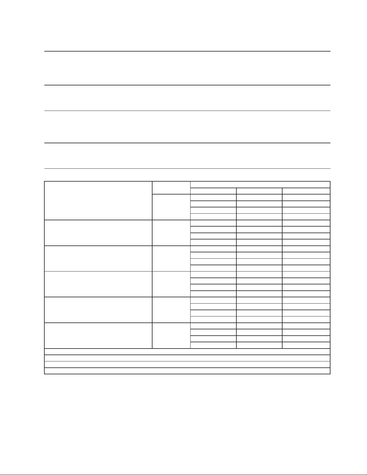
85
17a. F-801MWJ
S
p
ecification Shee
t
AC SUPPLY VOLTAGE 115/60/1
COMPRESSOR 115/60/1 7.5 RLA 54.5 LRA
GEAR MOTOR 115 V 3.0 FLA 200W
FAN MOTOR 115 V 1.0 FLA 1/15 HP
OTHER 115 V 0.03 A
MAXIMUM FUSE SIZE 15
A
MAX. HACR BREAKER
(
USA ONLY
)
15
A
MAX. CIRC. BREAKER
(
CANADA ONLY
)
15
A
MINIMUM CIRCUIT AMPACITY 15
A
ELECTRIC & WATER CONSUMPTION 90/70°F 70/50°F
ELECTRIC W
(
kWH/100 lbs.
)
960
(
3.90
)
963
(
3.39
)
POTABLE WATER 73
(
12.0
)
82
(
12.0
)
WATER-COOLED CONDENSER 602
(
119.0
)
334
(
49.1
)
g
al./24HR
(g
al./100 lbs.
)
SHAPE OF ICE Flake
ICE HARDNESS A
pp
rox. 76.9%, Ice
(
90/70°F, Conductivit
y
200
µ
s/cm
)
BIN CONTROL SYSTEM Photoelectric Senso
r
REFRIGERANT CHARGE R404A, 0 lb. 10.6 oz.
(
300
g)
Performance Data Shee
t
APPROXIMATE Ambien
t
ICE PRODUCTION Tem
p
. °F
(
°C
)
PER 24 HR.
70 (21)
680
(
309
)
681
(
309
)
663
(
301
)
80 (26)
647
(
293
)
631
(
286
)
615
(
279
)
90 (32)
599
(
272
)
605
(
274
)
570
(
258
)
lbs./da
y (
k
g
/da
y)
100 (38)
556
(
252
)
542
(
246
)
506
(
230
)
APPROXIMATE ELECTRIC
70 (21)
963
-- 962 -- 962 --
CONSUMPTION
80 (26)
962 -- 961 -- 961 --
90 (32)
961 --
960
-- 963 --
watts
100 (38)
967 -- 970 --
973
--
APPROXIMATE WATER
70 (21)
416
(
1573
)
684
(
2589
)
1544
(
5843
)
CONSUMPTION PER 24 HR.
80 (26)
412
(
1558
)
678
(
2566
)
1538
(
5821
)
(
TOTAL
)
90 (32)
406
(
1537
)
675
(
2555
)
1532
(
5800
)
g
al. / da
y (
l/da
y)
100 (38)
401
(
1517
)
667
(
2526
)
1525
(
5771
)
EVAPORATOR OUTLET TEMP.
70 (21)
17
(
(
-8
)
)
18
(
(
-8
)
)
18
(
(
-8
)
)
°F
(
°C
)
80 (26)
18
(
(
-8
)
)
18
(
(
-8
)
)
18
(
(
-8
)
)
90 (32)
18
(
(
-8
)
)
18
(
(
-8
)
)
18
(
(
-8
)
)
100 (38)
19
(
(
-7
)
)
19
(
(
-7
)
)
20
(
(
-7
)
)
HEAD PRESSURE
70 (21)
228
(
16.0
)
229
(
16.1
)
230
(
16.2
)
80 (26)
231
(
16.2
)
232
(
16.3
)
233
(
16.4
)
90 (32)
234
(
16.4
)
235
(
16.5
)
238
(
16.7
)
PSIG
(
k
g
/cm
2
G
)
100 (38)
242
(
17.0
)
245
(
17.2
)
248
(
17.5
)
SUCTION PRESSURE
70 (21)
41
(
2.9
)
41
(
2.9
)
41
(
2.9
)
PSIG
(
k
g
/cm
2
G
)
80 (26)
41
(
2.9
)
41
(
2.9
)
41
(
2.9
)
90 (32)
41
(
2.9
)
41
(
2.9
)
41
(
2.9
)
100 (38)
41
(
2.9
)
42
(
2.9
)
42
(
3.0
)
25
g
al/h
(
AT 90°F / WT 70°F
)
Less than 7 PSI
G
BTU/h
(
AT 90°F / WT 70°F
)
BTU/h
(
AT 90°F / WT 70°F
)
WATER FLOW FOR CONDENSER
PRESSURE DROP OF COOLING WATER LINE
HEAT OF REJECTION FROM CONDENSER 6,200
HEAT OF REJECTION FROM COMPRESSOR 900
Water Temp. °F (°C)
50 (10) 70 (21) 90 (32)
ENG F-013.0.1196
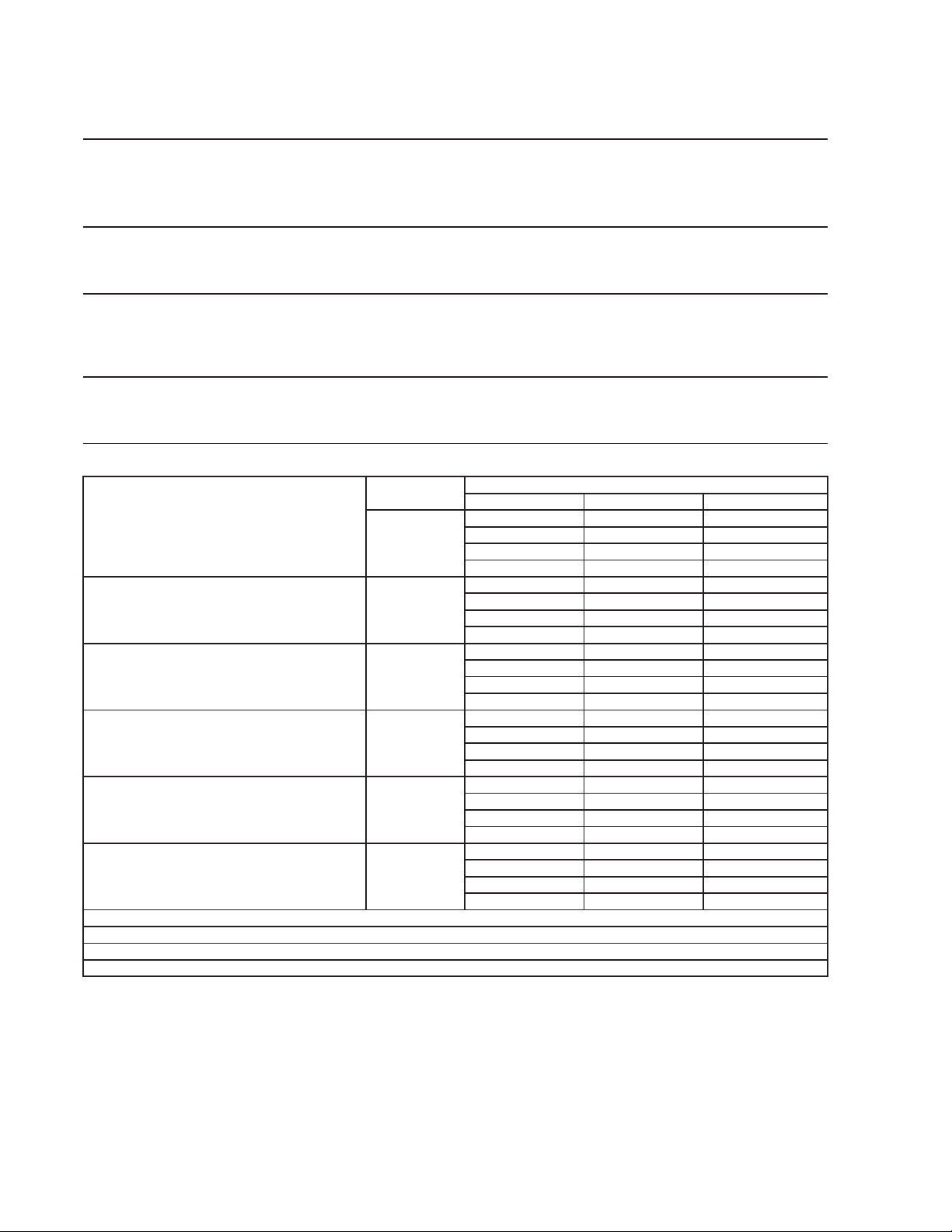
86
17b. F-801MWJ-C
S
p
ecification Shee
t
AC SUPPLY VOLTAGE 115/60/1
COMPRESSOR 115/60/1 7.5 RLA 54.5 LRA
GEAR MOTOR 115 V 3.0 FLA 200W
FAN MOTOR 115 V 1.0 FLA 1/15 HP
OTHER 115 V 0.03 A
MAXIMUM FUSE SIZE 15
A
MAX. HACR BREAKER
(
USA ONLY
)
15
A
MAX. CIRC. BREAKER
(
CANADA ONLY
)
15
A
MINIMUM CIRCUIT AMPACITY 15
A
ELECTRIC & WATER CONSUMPTION 90/70°F 70/50°F
ELECTRIC W
(
kWH/100 lbs.
)
977
(
4.13
)
990
(
3.76
)
POTABLE WATER 70
(
12.0
)
76
(
12.0
)
WATER-COOLED CONDENSER 634
(
120.0
)
332
(
51.6
)
g
al./24HR
(g
al./100 lbs.
)
SHAPE OF ICE Cubele
t
ICE HARDNESS A
pp
rox. 82%, Ice
(
90/70°F, Conductivit
y
200
µ
s/cm
)
BIN CONTROL SYSTEM Photoelectric Senso
r
REFRIGERANT CHARGE R404A, 0 lb. 10.6 oz.
(
300
g)
Performance Data Shee
t
APPROXIMATE Ambien
t
ICE PRODUCTION Tem
p
. °F
(
°C
)
PER 24 HR.
70 (21)
632
(
287
)
637
(
289
)
623
(
282
)
80 (26)
609
(
276
)
595
(
270
)
582
(
264
)
90 (32)
569
(
258
)
580
(
263
)
544
(
247
)
lbs./da
y (
k
g
/da
y)
100 (38)
532
(
241
)
520
(
236
)
484
(
220
)
APPROXIMATE ELECTRIC
70 (21)
990
-- 988 -- 986 --
CONSUMPTION
80 (26)
984 -- 983 -- 981 --
90 (32)
979 --
977
-- 984 --
watts
100 (38)
991 -- 998 --
1006
--
APPROXIMATE WATER
70 (21)
408
(
1545
)
711
(
2690
)
1648
(
6239
)
CONSUMPTION PER 24 HR.
80 (26)
405
(
1535
)
706
(
2672
)
1644
(
6221
)
(
TOTAL
)
90 (32)
401
(
1517
)
704
(
2665
)
1639
(
6204
)
g
al. / da
y (
l/da
y)
100 (38)
396
(
1500
)
697
(
2637
)
1632
(
6176
)
EVAPORATOR OUTLET TEMP.
70 (21)
15
(
(
-9
)
)
15
(
(
-9
)
)
16
(
(
-9
)
)
°F
(
°C
)
80 (26)
16
(
(
-9
)
)
16
(
(
-9
)
)
16
(
(
-9
)
)
90 (32)
17
(
(
-9
)
)
17
(
(
-8
)
)
18
(
(
-8
)
)
100 (38)
18
(
(
-8
)
)
19
(
(
-7
)
)
19
(
(
-7
)
)
HEAD PRESSURE
70 (21)
229
(
16.1
)
229
(
16.1
)
229
(
16.1
)
80 (26)
230
(
16.1
)
230
(
16.2
)
231
(
16.2
)
90 (32)
231
(
16.2
)
231
(
16.3
)
236
(
16.6
)
PSIG
(
k
g
/cm
2
G
)
100 (38)
240
(
16.9
)
245
(
17.2
)
249
(
17.5
)
SUCTION PRESSURE
70 (21)
38
(
2.7
)
38
(
2.7
)
39
(
2.7
)
PSIG
(
k
g
/cm
2
G
)
80 (26)
39
(
2.7
)
39
(
2.7
)
39
(
2.7
)
90 (32)
39
(
2.8
)
39
(
2.8
)
40
(
2.8
)
100 (38)
41
(
2.8
)
41
(
2.9
)
42
(
2.9
)
26
g
al/h
(
AT 90°F / WT 70°F
)
Less than 7 PSI
G
BTU/h
(
AT 90°F / WT 70°F
)
BTU/h
(
AT 90°F / WT 70°F
)
WATER FLOW FOR CONDENSER
PRESSURE DROP OF COOLING WATER LINE
HEAT OF REJECTION FROM CONDENSER 6,000
HEAT OF REJECTION FROM COMPRESSOR 900
Water Temp. °F (°C)
50 (10) 70 (21) 90 (32)
ENG F-013.0.1196
87
18a. F-1001MAJ
S
p
ecification Sheet
A
C SUPPLY VOLTAGE 115/60/1
COMPRESSOR 115 V 11.2 RLA 93 LRA
GEAR MOTOR 115 V 3.0 FLA 200 W
FAN MOTOR 115 V 1.0 FLA 1/15 HP
OTHER 120 V 0.03 A
MAXIMUM FUSE SIZ
E
20
A
MAX. HACR BREAKER
(
USA ONLY
)
20
A
MAX. CIRC. BREAKER
(
CANADA ONLY
)
20
A
MINIMUM CIRCUIT AMPACIT
Y
20
A
ELECTRIC & WATER CONSUMPTION 90/70°F 70/50°F
ELECTRIC W
(
kWH/100 lbs.
)
1200
(
4.52
)
1160
(
3.80
)
WATER
g
al./24HR
(g
al./100 lbs.
)
90
(
12.0
)
116
(
12.0
)
SHAPE OF ICE Flake
ICE HARDNESS
App
rox. 73.6%, Ice
(
90/70°F, Conductivit
y
200
µ
s/cm
)
BIN CONTROL SYSTEM Proximit
y
Switch
(
BC
(
Mechanical
))
REFRIGERANT CHARGE R-404A, 2 lb. 4.1 oz.
(
1025
g)
Performance Data Sheet
A
PPROXIMATE
A
mbien
t
ICE PRODUCTION Tem
p
. °F
(
°C
)
PER 24 HR.
70 (21)
970 440 951 431 910 413
80 (26)
871 395 834 378 798 362
90 (32)
764 347 748 339 701 318
lbs./da
y (
k
g
/da
y)
100 (38)
671 304 642 291 595 270
A
PPROXIMATE ELECTRIC
70 (21)
1160 -
-
1166 -
-
1171 -
-
CONSUMPTION
80 (26)
1177 -
-
1183 -
-
1189 -
-
90 (32)
1194 -
-
1200 -
-
1205 -
-
watts
100 (38)
1210 -
-
1215 -
-
1220 -
-
A
PPROXIMATE WATER
70 (21)
116 441 114 432 109 414
CONSUMPTION PER 24 HR.
80 (26)
105 396 100 379 96 363
90 (32)
92 347 90 340 84 318
g
al. / da
y (
l/da
y)
100 (38)
81 305 77 292 71 270
EVAPORATOR OUTLET TEMP.
70 (21)
19
(
-7
)
20
(
-7
)
20
(
-7
)
°F
(
°C
)
80 (26)
20
(
-7
)
20
(
-6
)
21
(
-6
)
90 (32)
21
(
-6
)
21
(
-6
)
22
(
-6
)
100 (38)
23
(
-5
)
24
(
-5
)
25
(
-4
)
HEAD PRESSURE
70 (21)
213 15.0 222 15.6 230 16.2
PSIG
(
k
g
/cm
2
G
)
80 (26)
239 16.8 248 17.4 257 18.0
90 (32)
265 18.6 274 19.3 284 20.0
100 (38)
295 20.7 305 21.4 315 22.1
SUCTION PRESSURE
70 (21)
32 2.2 33 2.3 34 2.4
PSIG
(
k
g
/cm
2
G
)
80 (26)
35 2.4 35 2.5 36 2.5
90 (32)
37 2.6 38 2.7 39 2.7
100 (38)
40 2.8 40 2.8 41 2.9
9100 BTU/h
(
AT 90°F / WT 70°F
)
TOTAL HEAT OF REJECTION
50 (10) 70 (21) 90 (32)
Water Temp. °F (°C)
ENG F-013.0.1196
88
18b. F-1001MAJ-C
S
p
ecification Sheet
A
C SUPPLY VOLTAGE 115/60/1
COMPRESSOR 115 V 11.2 RLA 93 LRA
GEAR MOTOR 115 V 3.0 FLA 200 W
FAN MOTOR 115 V 1.0 FLA 1/15 HP
OTHER 120 V 0.03 A
MAXIMUM FUSE SIZ
E
20
A
MAX. HACR BREAKER
(
USA ONLY
)
20
A
MAX. CIRC. BREAKER
(
CANADA ONLY
)
20
A
MINIMUM CIRCUIT AMPACIT
Y
20
A
ELECTRIC & WATER CONSUMPTION 90/70°F 70/50°F
ELECTRIC W
(
kWH/100 lbs.
)
1516
(
5.27
)
1469
(
3.90
)
WATER
g
al./24HR
(g
al./100 lbs.
)
79
(
12.0
)
109
(
12.0
)
SHAPE OF ICE Cubelet
ICE HARDNESS
App
rox. 75.6%, Ice
(
90/70°F, Conductivit
y
200
µ
s/cm
)
BIN CONTROL SYSTEM Proximit
y
Switch
(
BC
(
Mechanical
))
REFRIGERANT CHARGE
Performance Data Sheet
A
PPROXIMATE
A
mbien
t
ICE PRODUCTION Tem
p
. °F
(
°C
)
PER 24 HR.
70 (21)
910 413 869 394 832 378
80 (26)
797 362 764 346 731 332
90 (32)
700 318 656 298 643 292
lbs./da
y (
k
g
/da
y)
100 (38)
616 279 590 267 575 261
A
PPROXIMATE ELECTRIC
70 (21)
1469 -
-
1476 -
-
1482 -
-
CONSUMPTION
80 (26)
1489 -
-
1496 -
-
1503 -
-
90 (32)
1509 -
-
1516 -
-
1533 -
-
watts
100 (38)
1551 -
-
1568 -
-
1585 -
-
A
PPROXIMATE WATER
70 (21)
109 414 104 395 100 378
CONSUMPTION PER 24 HR.
80 (26)
96 362 92 347 88 332
(
TOTAL
)
90 (32)
84 318 79 298 77 292
g
al. / da
y (
l/da
y)
100 (38)
74 280 71 268 69 261
EVAPORATOR OUTLET TEMP.
70 (21)
18
(
-8
)
18
(
-8
)
19
(
-7
)
°F
(
°C
)
80 (26)
20
(
-7
)
21
(
-6
)
21
(
-6
)
90 (32)
22
(
-5
)
23
(
-5
)
24
(
-5
)
100 (38)
25
(
-4
)
26
(
-4
)
27
(
-3
)
HEAD PRESSURE
70 (21)
213 15.0 222 15.6 230 16.2
PSIG
(
k
g
/cm
2
G
)
80 (26)
239 16.8 248 17.4 257 18.0
90 (32)
265 18.6 274 19.3 284 20.0
100 (38)
295 20.7 305 21.4 315 22.1
SUCTION PRESSURE
70 (21)
32 2.2 33 2.3 34 2.4
PSIG
(
k
g
/cm
2
G
)
80 (26)
35 2.4 35 2.5 36 2.5
90 (32)
37 2.6 38 2.7 39 2.7
100 (38)
40 2.8 40 2.8 41 2.9
9050 BTU/h
(
AT 90°F / WT 70°F
)
TOTAL HEAT OF REJECTION
R-404A, 2 lb. 4.1 oz. (1025 g)
Water Temp. °F (°C)
50 (10) 70 (21) 90 (32)
ENG F-013.0.1196
89
19a. F-1001MWJ
S
p
ecification Sheet
A
C SUPPLY VOLTAGE 115/60/1
COMPRESSOR 115 V 11.2 RLA 93 LRA
GEAR MOTOR 115 V 3.0 FLA 200 W
FAN MOTOR -
OTHER 120 V 0.03 A
MAXIMUM FUSE SIZ
E
20
A
MAX. HACR BREAKER
(
USA ONLY
)
20
A
MAX. CIRC. BREAKER
(
CANADA ONLY
)
20
A
MINIMUM CIRCUIT AMPACIT
Y
20
A
ELECTRIC & WATER CONSUMPTION 90/70°F 70/50°F
ELECTRIC W
(
kWH/100 lbs.
)
1160
(
4.0
)
1155
(
3.8
)
POTABLE WATER 90
(
12.0
)
107
(
12.0
)
WATER-COOLED CONDENSER 869
(
125.0
)
481
(
54.0
)
g
al./24HR
(g
al./100 lbs.
)
SHAPE OF ICE Flake
ICE HARDNESS
App
rox. 74.1%, Ice
(
90/70°F, Conductivit
y
200
µ
s/cm
)
BIN CONTROL SYSTEM Proximit
y
Switch
(
BC
(
Mechanical
))
REFRIGERANT CHARGE
Performance Data Sheet
A
PPROXIMATE
A
mbien
t
ICE PRODUCTION Tem
p
. °F
(
°C
)
PER 24 HR.
70 (21)
890 404 875 397 852 386
80 (26)
828 376 806 366 784 356
90 (32)
763 346 750 340 722 328
lbs./da
y (
k
g
/da
y)
100 (38)
702 319 683 310 655 297
A
PPROXIMATE ELECTRIC
70 (21)
1155 -
-
1156 -
-
1156 -
-
CONSUMPTION
80 (26)
1157 -
-
1158 -
-
1159 -
-
90 (32)
1159 -
-
1160 -
-
1166 -
-
watts
100 (38)
1173 -
-
1179 -
-
1185 -
-
A
PPROXIMATE WATER
70 (21)
588 2225 964 3649 2939 11125
CONSUMPTION PER 24 HR.
80 (26)
580 2197 956 3618 2931 11094
(
TOTAL
)
90 (32)
573 2167 949 3592 2924 11066
g
al. / da
y (
l/da
y)
100 (38)
565 2140 941 3562 2916 11036
EVAPORATOR OUTLET TEMP.
70 (21)
23
(
-5
)
23
(
-5
)
23
(
-5
)
°F
(
°C
)
80 (26)
23
(
-5
)
23
(
-5
)
23
(
-5
)
90 (32)
23
(
-5
)
23
(
-5
)
23
(
-5
)
100 (38)
24
(
-5
)
24
(
-4
)
25
(
-4
)
HEAD PRESSURE
70 (21)
263 18.5 263 18.5 264 18.5
80 (26)
264 18.6 265 18.6 265 18.6
90 (32)
266 18.7 266 18.7 267 18.7
PSIG
(
k
g
/cm
2
G
)
100 (38)
268 18.8 268 18.9 269 18.9
SUCTION PRESSURE
70 (21)
33 2.3 33 2.3 33 2.3
PSIG
(
k
g
/cm
2
G
)
80 (26)
33 2.3 34 2.4 34 2.4
90 (32)
34 2.4 34 2.4 34 2.4
100 (38)
35 2.4 35 2.4 35 2.5
36
g
al/h
(
AT 90°F / WT 70°F
)
Less than 7 PSIG
7110 BTU/h
(
AT 90°F / WT 70°F
)
1340 BTU/h
(
AT 90°F / WT 70°F
)
70 (21) 90 (32)
R-404A, 12.3 oz (350 g)
Water Temp. °F (°C)
HEAT OF REJECTION FROM CONDENSER
HEAT OF REJECTION FROM COMPRESSOR
WATER FLOW FOR CONDENSER
PRESSURE DROP OF COOLING WATER LINE
50 (10)
ENG F-013.0.1196
90
19b. F-1001MWJ-C
S
p
ecificaiton Sheet
A
C SUPPLY VOLTAGE 115/60/1
COMPRESSOR 115 V 11.2 RLA 93 LRA
GEAR MOTOR 115 V 3.0 FLA 200 W
FAN MOTOR -
OTHER 120 V 0.03 A
MAXIMUM FUSE SIZ
E
20
A
MAX. HACR BREAKER
(
USA ONLY
)
20
A
MAX. CIRC. BREAKER
(
CANADA ONLY
)
20
A
MINIMUM CIRCUIT AMPACIT
Y
20
A
ELECTRIC & WATER CONSUMPTION 90/70°F 70/50°F
ELECTRIC W
(
kWH/100 lbs.
)
1205
(
4.1
)
1200
(
3.8
)
POTABLE WATER 84
(
12.0
)
95
(
12.0
)
WATER-COOLED CONDENSER 857
(
130.0
)
479
(
61.0
)
g
al./24HR
(g
al./100 lbs.
)
SHAPE OF ICE Cubelet
ICE HARDNESS
App
rox. 80.8%, Ice
(
90/70°F, Conductivit
y
200
µ
s/cm
)
BIN CONTROL SYSTEM Proximit
y
Switch
(
BC
(
Mechanical
))
REFRIGERANT CHARGE
Performance Data Sheet
A
PPROXIMATE
A
mbien
t
ICE PRODUCTION Tem
p
. °F
(
°C
)
PER 24 HR.
70 (21)
790 358 788 357 770 349
80 (26)
751 341 734 333 717 325
90 (32)
700 317 703 319 667 303
lbs./da
y (
k
g
/da
y)
100 (38)
651 296 636 289 600 272
A
PPROXIMATE ELECTRIC
70 (21)
1200 -
-
1201 -
-
1201 -
-
CONSUMPTION
80 (26)
1202 -
-
1203 -
-
1204 -
-
90 (32)
1204 -
-
1205 -
-
1206 -
-
watts
100 (38)
1208 -
-
1209 -
-
1210 -
-
A
PPROXIMATE WATER
70 (21)
574 2172 942 3564 2610 9880
CONSUMPTION PER 24 HR.
80 (26)
569 2155 935 3539 2604 9856
(
TOTAL
)
90 (32)
563 2131 931 3525 2598 9834
g
al. / da
y (
l/da
y)
100 (38)
557 2109 923 3495 2590 9803
EVAPORATOR OUTLET TEMP.
70 (21)
23
(
-5
)
23
(
-5
)
23
(
-5
)
°F
(
°C
)
80 (26)
23
(
-5
)
23
(
-5
)
23
(
-5
)
90 (32)
23
(
-5
)
23
(
-5
)
23
(
-5
)
100 (38)
24
(
-5
)
24
(
-4
)
25
(
-4
)
HEAD PRESSURE
70 (21)
263 18.5 263 18.5 264 18.5
80 (26)
264 18.6 265 18.6 265 18.6
90 (32)
266 18.7 266 18.7 267 18.7
PSIG
(
k
g
/cm
2
G
)
100 (38)
268 18.8 268 18.9 269 18.9
SUCTION PRESSURE
70 (21)
33 2.3 33 2.3 33 2.3
PSIG
(
k
g
/cm
2
G
)
80 (26)
33 2.3 34 2.4 34 2.4
90 (32)
34 2.4 34 2.4 34 2.4
100 (38)
35 2.4 35 2.4 35 2.5
36
g
al/h
(
AT 90°F / WT 70°F
)
Less than 7 PSIG
7110 BTU/h
(
AT 90°F / WT 70°F
)
1340 BTU/h
(
AT 90°F / WT 70°F
)
HEAT OF REJECTION FROM CONDENSER
HEAT OF REJECTION FROM COMPRESSOR
WATER FLOW FOR CONDENSER
PRESSURE DROP OF COOLING WATER LINE
R-404A, 12.3 oz (350 g)
Water Temp. °F (°C)
50 (10) 70 (21) 90 (32)
ENG F-013.0.1196

91
20a. F-1001MRJ
S
p
ecification Sheet
A
C SUPPLY VOLTAGE 115/60/1
COMPRESSOR 115 V 11.2 RLA 93 LRA
GEAR MOTOR 115 V 3.0 FLA 200 W
FAN MOTOR REMOTE 120 V 1.0 FLA
OTHER 120 V 0.53 A
MAXIMUM FUSE SIZ
E
20
A
MAX. HACR BREAKER
(
USA ONLY
)
20
A
MAX. CIRC. BREAKER
(
CANADA ONLY
)
20
A
MINIMUM CIRCUIT AMPACIT
Y
20
A
ELECTRIC & WATER CONSUMPTION 90/70°F 70/50°F
ELECTRIC W
(
kWH/100 lbs.
)
1295
(
4.73
)
1285
(
4.1
)
WATER
g
al./24HR
(g
al./100 lbs.
)
86
(
12.0
)
112
(
12.0
)
SHAPE OF ICE Flake
ICE HARDNESS
App
rox. 66.9%, Ice
(
90/70°F, Conductivit
y
200
µ
s/cm
)
BIN CONTROL SYSTEM Proximit
y
Switch
(
BC
(
Mechanical
))
CONDENSER
A
ir-cooled Remote Condenser unit URC-5F Recommended
REFRIGERANT CHARGE
R-404A, 4 lb. 1.2 oz. (1850 g)
(Ice Maker: 2 lb. 3.2 oz., Cond. Unit: 1 lb. 14 oz. )
Performance Data Sheet
A
PPROXIMATE
A
mbien
t
ICE PRODUCTION Tem
p
. °F
(
°C
)
PER 24 HR.
70 (21)
930 422 902 409 867 393
80 (26)
834 378 802 364 771 350
90 (32)
741 336 713 323 685 311
lbs./da
y (
k
g
/da
y)
100 (38)
659 299 633 287 605 274
A
PPROXIMATE ELECTRIC
70 (21)
1285 -
-
1286 -
-
1288 -
-
CONSUMPTION
80 (26)
1289 -
-
1291 -
-
1292 -
-
90 (32)
1294 -
-
1295 -
-
1303 -
-
watts
100 (38)
1310 -
-
1318 -
-
1325 -
-
A
PPROXIMATE WATER
70 (21)
112 423 108 410 104 394
CONSUMPTION PER 24 HR.
80 (26)
100 379 96 364 93 350
90 (32)
89 337 86 324 82 311
g
al. / da
y (
l/da
y)
100 (38)
79 299 76 288 73 275
EVAPORATOR OUTLET TEMP.
70 (21)
23
(
-5
)
24
(
-5
)
24
(
-4
)
°F
(
°C
)
80 (26)
25
(
-4
)
25
(
-4
)
26
(
-4
)
90 (32)
26
(
-3
)
27
(
-3
)
27
(
-3
)
100 (38)
28
(
-3
)
28
(
-2
)
28
(
-2
)
HEAD PRESSURE
70 (21)
221 15.5 226 15.9 231 16.2
80 (26)
236 16.6 241 16.9 246 17.3
90 (32)
251 17.6 256 18.0 266 18.7
PSIG
(
k
g
/cm
2
G
)
100 (38)
276 19.4 285 20.0 295 20.7
SUCTION PRESSURE
70 (21)
33 2.3 33 2.3 34 2.4
PSIG
(
k
g
/cm
2
G
)
80 (26)
34 2.4 35 2.4 35 2.5
90 (32)
36 2.5 36 2.5 37 2.6
100 (38)
38 2.6 38 2.7 39 2.7
CONDENSER VOLUME 74.5 cu in
7660 BTU/h
(
AT 90°F / WT 70°F
)
1380 BTU/h
(
AT 90°F / WT 70°F
)
HEAT OF REJECTION FROM CONDENSER
HEAT OF REJECTION FROM COMPRESSOR
Water Temp. °F (°C)
50 (10) 70 (21) 90 (32)
ENG F-013.0.1196
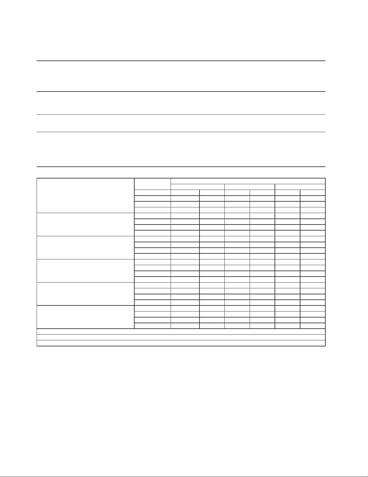
92
20b. F-1001MRJ-C
Specification Sheet
A
C SUPPLY VOLTAGE 115/60/1
COMPRESSOR 115 V 11.2 RLA 93 LRA
GEAR MOTOR 115 V 3.0 FLA 200 W
FAN MOTOR REMOTE 120 V 1.0 FLA
OTHER 120 V 0.53 A
MAXIMUM FUSE SIZ
E
20
A
MAX. HACR BREAKER
(
USA ONLY
)
20
A
MAX. CIRC. BREAKER
(
CANADA ONLY
)
20
A
MINIMUM CIRCUIT AMPACIT
Y
20
A
ELECTRIC & WATER CONSUMPTION 90/70°F 70/50°F
ELECTRIC W
(
kWH/100 lbs.
)
1310
(
5.25
)
1300
(
4.6
)
WATER
g
al./24HR
(g
al./100 lbs.
)
86
(
12.0
)
101
(
12.0
)
SHAPE OF ICE Cubelet
ICE HARDNESS
App
rox. 81.1%, Ice
(
90/70°F, Conductivit
y
200
µ
s/cm
)
BIN CONTROL SYSTEM Proximit
y
Switch
(
BC
(
Mechanical
))
CONDENSER
A
ir-cooled Remote Condenser unit URC-5F Recommended
REFRIGERANT CHARGE
R-404A, 4 lb. 1.2 oz. (1850 g)
(Ice Maker: 2 lb. 3.2 oz., Cond. Unit: 1 lb. 14 oz. )
Performance Data Sheet
A
PPROXIMATE
A
mbien
t
ICE PRODUCTION Tem
p
. °F
(
°C
)
PER 24 HR.
70 (21)
840 381 825 374 797 362
80 (26)
771 350 745 338 720 327
90 (32)
696 316 683 310 650 295
lbs./da
y (
k
g
/da
y)
100 (38)
629 285 608 276 575 261
A
PPROXIMATE ELECTRIC
70 (21)
1300 -
-
1301 -
-
1303 -
-
CONSUMPTION
80 (26)
1304 -
-
1306 -
-
1307 -
-
90 (32)
1309 -
-
1310 -
-
1318 -
-
watts
100 (38)
1325 -
-
1333 -
-
1340 -
-
A
PPROXIMATE WATER
70 (21)
101 382 99 375 96 362
CONSUMPTION PER 24 HR.
80 (26)
93 350 89 339 86 327
(
TOTAL
)
90 (32)
84 316 82 310 78 296
g
al. / da
y (
l/da
y)
100 (38)
75 286 73 276 69 261
EVAPORATOR OUTLET TEMP.
70 (21)
23
(
-5
)
24
(
-5
)
24
(
-4
)
°F
(
°C
)
80 (26)
25
(
-4
)
25
(
-4
)
26
(
-4
)
90 (32)
26
(
-3
)
27
(
-3
)
27
(
-3
)
100 (38)
28
(
-3
)
28
(
-2
)
28
(
-2
)
HEAD PRESSURE
70 (21)
220 15.5 225 15.8 230 16.2
80 (26)
235 16.5 241 16.9 246 17.3
90 (32)
251 17.6 256 18.0 266 18.7
PSIG
(
k
g
/cm
2
G
)
100 (38)
276 19.4 285 20.0 295 20.7
SUCTION PRESSURE
70 (21)
34 2.4 34 2.4 35 2.4
PSIG
(
k
g
/cm
2
G
)
80 (26)
35 2.5 36 2.5 36 2.5
90 (32)
37 2.6 37 2.6 38 2.7
100 (38)
39 2.7 39 2.8 40 2.8
CONDENSER VOLUME 74.5 cu in
7840 BTU/h
(
AT 90°F / WT 70°F
)
1400 BTU/h
(
AT 90°F / WT 70°F
)
HEAT OF REJECTION FROM CONDENSER
HEAT OF REJECTION FROM COMPRESSOR
Water Temp. °F (°C)
50 (10) 70 (21) 90 (32)
ENG F-013.0.1196
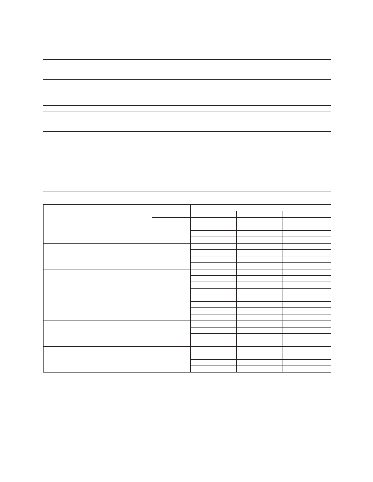
93
21a. F-1001MLJ
S
p
ecification Shee
t
AC SUPPLY VOLTAGE 115/60/1
GEAR MOTOR 115 V 3.0 FLA 200 W
OTHER 120 V 0.53 A
MAXIMUM FUSE SIZE 15
A
MAX. HACR BREAKER
(
USA ONLY
)
15
A
MAX. CIRC. BREAKER
(
CANADA ONLY
)
15
A
MINIMUM CIRCUIT AMPACITY 15
A
SHAPE OF ICE Flake
ELECTRIC & WATER CONSUMPTION 90/70°F 70/50°F
ELECTRIC W
(
kWH/100 lbs.
)
130
(
1.89
)
130
(
1.4
)
WATER
g
al./24HR
(g
al./100 lbs.
)
106
(
12.0
)
138
(
12.0
)
SHAPE OF ICE Flake
ICE HARDNESS A
pp
rox. 73.8%, Ice
(
90/70°F, Conductivit
y
200
µ
s/cm
)
BIN CONTROL SYSTEM Mechanical Bin Control
(
Proximit
y
Sw.
)
CONDENSING UNIT
REFRIGERANT CONTROL
Evaporator Pressure Regulato
r
REFRIGERANT CHARGE
R-404A,
Performance Data Shee
t
APPROXIMATE Ambien
t
ICE PRODUCTION Tem
p
. °F
(
°C
)
PER 24 HR.
70 (21)
1150
(
522
)
1124
(
510
)
1074
(
487
)
80 (26)
1026
(
465
)
980
(
444
)
936
(
425
)
90 (32)
894
(
406
)
871
(
395
)
816
(
370
)
lbs./da
y (
k
g
/da
y)
100 (38)
780
(
354
)
745
(
338
)
690
(
313
)
APPROXIMATE ELECTRIC
70 (21)
130
-- 130 -- 130 --
CONSUMPTION
80 (26)
130 -- 130 -- 130 --
90 (32)
130 --
130
-- 131 --
watts
100 (38)
133 -- 134 --
135
--
APPROXIMATE WATER
70 (21)
138
(
523
)
135
(
511
)
129
(
488
)
CONSUMPTION PER 24 HR.
80 (26)
123
(
466
)
118
(
445
)
112
(
425
)
(
TOTAL
)
90 (32)
107
(
406
)
105
(
396
)
98
(
371
)
g
al. / da
y (
l/da
y)
100 (38)
94
(
354
)
89
(
338
)
83
(
314
)
EVAPORATOR OUTLET TEMP.
70 (21)
21
(
(
-6
)
)
21
(
(
-6
)
)
21
(
(
-6
)
)
°F
(
°C
)
80 (26)
21
(
(
-6
)
)
21
(
(
-6
)
)
21
(
(
-6
)
)
90 (32)
21
(
(
-6
)
)
21
(
(
-6
)
)
22
(
(
-6
)
)
100 (38)
22
(
(
-6
)
)
23
(
(
-5
)
)
23
(
(
-5
)
)
HEAD PRESSURE
70 (21)
106
(
7.4
)
111
(
7.8
)
117
(
8.2
)
PSIG
(
k
g
/cm
2
G
)
80 (26)
122
(
8.6
)
127
(
8.9
)
132
(
9.3
)
90 (32)
138
(
9.7
)
143
(
10.0
)
149
(
10.5
)
100 (38)
155
(
10.9
)
160
(
11.3
)
166
(
11.7
)
SUCTION PRESSURE
70 (21)
26
(
1.8
)
27
(
1.9
)
28
(
2.0
)
PSIG
(
k
g
/cm
2
G
)
80 (26)
29
(
2.0
)
30
(
2.1
)
31
(
2.2
)
90 (32)
32
(
2.2
)
33
(
2.3
)
34
(
2.4
)
100 (38)
34
(
2.4
)
35
(
2.4
)
35
(
2.5
)
50 (10) 70 (21) 90 (32)
Required refrigeration capacity for ice maker is 5700 BTU/h
at discharge pressure 213 PSIG and suction pressure
31.2 PSIG with R-404A refrigerant.
Suction pressure needs to be 31.2 PSIG.
3.5 oz. (100 g Holding Charge)
Water Temp. °F (°C)
ENG F-013.0.1196
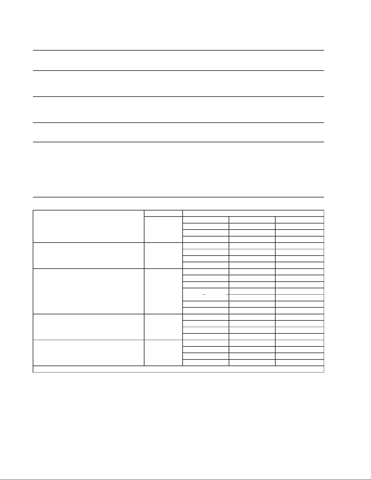
94
21b. F-1002MLJ
Specification Shee
t
AC SUPPLY VOLTAGE 115/60/1
GEAR MOTOR 115 V 3.0 FLA 200 W
OTHER 115 V 0.03 A
MAXIMUM FUSE SIZE 15
A
MAX. HACR BREAKER
(
USA ONLY
)
15
A
MAX. CIRC. BREAKER
(
CANADA ONLY
)
15
A
MINIMUM CIRCUIT AMPACITY 15
A
ELECTRIC & WATER CONSUMPTION
90/70°F 70/50°F
ELECTRIC W
(
kWH/100 lbs.
)
132(1.51) 130(1.20)
POTABLE WATER
96(12.0) 123(12.0)
g
al./24HR
(g
al./100 lbs.
)
SHAPE OF ICE
Flake
ICE HARDNESS
Approx. 72.8%, Ice (32/21 (90/70), Conductivity 200 µs/cm
)
BIN CONTROL SYSTEM
Photoelectric Senso
r
CONDENSING UNIT
REFRIGERANT CONTROL Eva
p
orator Pressure Re
g
ulator
(
EPR
)
REFRIGERANT CHARGE Nitrogen Holding Charge (5 PSIG
)
Can be used with refrigerant R404A, R407A, and R407
F
Performance Data Shee
t
APPROXIMATE Ambien
t
PER 24 HR.
70 (21)
1028
(
466 996
(
452
)
960
(
436
)
80 (26)
926
(
420 893
(
405
)
861
(
390
)
90 (32)
830
(
376
797
(
362
)
771
(
350
)
lbs./da
y (
k
g
/da
y)
100 (38)
743
(
337 717
(
325
)
690
(
313
)
APPROXIMATE ELECTRIC
70 (21)
130
-- 130 -- 131 --
CONSUMPTION
80 (26)
131 -- 131 -- 131 --
90 (32)
132 --
132
-- 133 --
watts
100 (38)
134 -- 134 --
135
--
APPROXIMATE WATER
70 (21)
123
(
467 120
(
453
)
115
(
436
)
CONSUMPTION PER 24 HR.
80 (26)
111
(
421 107
(
406
)
103
(
391
)
(
TOTAL
)
90 (32)
100
(
377
96
(
362
)
93
(
350
)
g
al. / da
y (
l/da
y)
100 (38)
89
(
338 86
(
326
)
83
(
314
)
°F
(
°C
)
80 (26)
17
(
(
-9
)
17
(
(
-8
)
)
17
(
(
-8
)
)
90 (32)
17
(
(
-8
)
18
(
(
-8
)
)
18
(
(
-8
)
)
100 (38)
19
(
(
-8
)
19
(
(
-7
)
)
19
(
(
-7
)
)
HEAD PRESSURE
70 (21)
205
(
14.4 212
(
14.9
)
219
(
15.4
)
80 (26)
226
(
15.9 233
(
16.4
)
240
(
16.9
)
90 (32)
247
(
17.3
254
(
17.8
)
259
(
18.2
)
PSIG
(
k
g
/cm2G
)
100 (38)
264
(
18.6 270
(
19.0
)
275
(
19.3
)
SUCTION PRESSURE
70 (21)
32
(
2.2 32
(
2.3
)
33
(
2.3
)
PSIG
(
k
g
/cm2G
)
80 (26)
33
(
2.3 34
(
2.4
)
34
(
2.4
)
90 (32)
35
(
2.4
35
(
2.5
)
36
(
2.5
)
100 (38)
37
(
2.6 37
(
2.6
)
38
(
2.7
)
HEAT OF REJECTION FROM CONDENSER 8,600 BTU/h (AT 90°F / WT 70°F)
Water Temp. °F (°C)
Required refrigeration capacity for ice maker is estiamted at 8,600BTU/h.
Suction pressure need to be set to (EPR):
R404A - 31PSIG
R407A - 22PSIG
R407F - 23PSIG
ENG F-013.0.1196
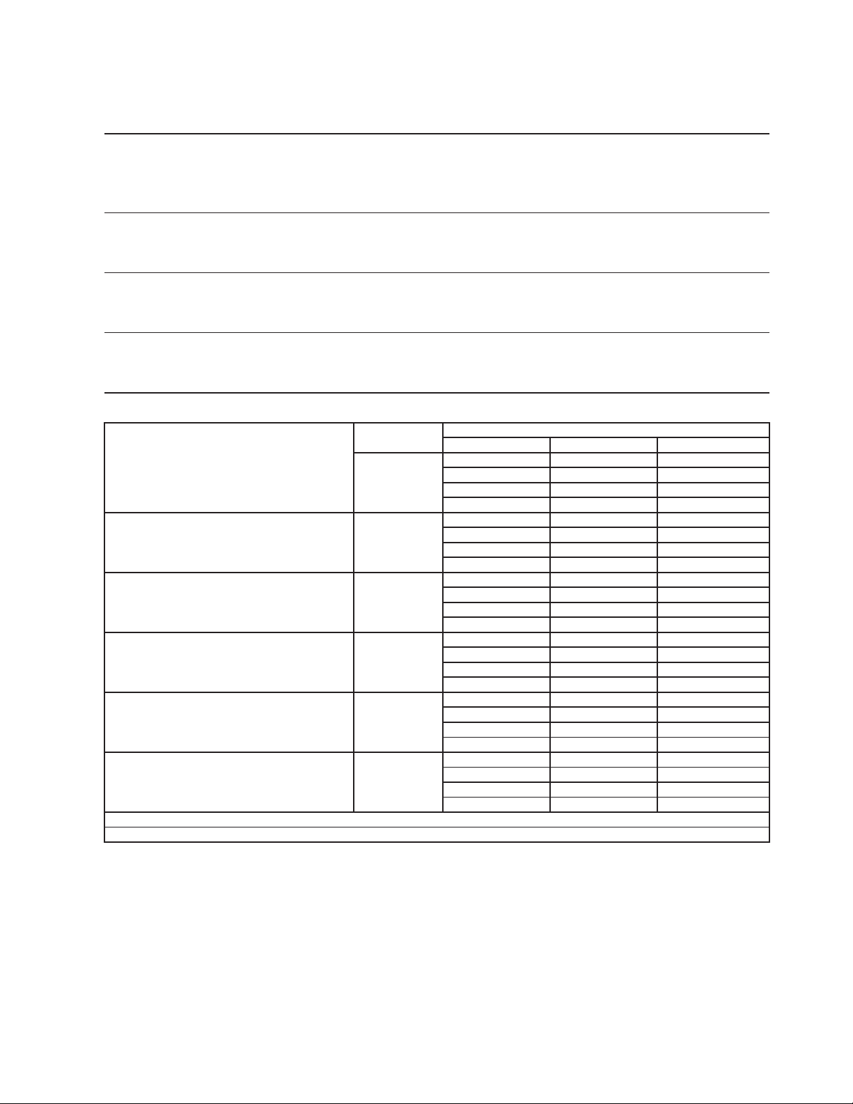
95
22a. F-1002MAJ
Specification Shee
t
AC SUPPLY VOLTAGE 115/60/1
COMPRESSOR 115/60/1 11.2 RLA 93 LRA
GEAR MOTOR 115 V 3.0 FLA 200 W
FAN MOTOR 115 V 1.0 FLA 1/15 HP
OTHER 115 V 0.03 A
MAXIMUM FUSE SIZE 20
A
MAX. HACR BREAKER
(
USA ONLY
)
20
A
MAX. CIRC. BREAKER
(
CANADA ONLY
)
20
A
MINIMUM CIRCUIT AMPACITY 20
A
ELECTRIC & WATER CONSUMPTION
90/70°F 70/50°F
ELECTRIC W
(
kWH/100 lbs.
)
1200(4.36
)
1160(3.09
)
POTABLE WATER
91(12.0) 118(12.0)
g
al./24HR
(g
al./100 lbs.
)
SHAPE OF ICE Flake
ICE HARDNESS A
pp
rox. 80.1%, Ice
(
90/70°F, Conductivit
y
200
µ
s/cm
)
BIN CONTROL SYSTEM Photoelectric Senso
r
REFRIGERANT CHARGE R404A, 2 lb. 4.2 oz.
(
1025
g)
Performance Data Shee
t
APPROXIMATE Ambien
t
ICE PRODUCTION Tem
p
. °F
(
°C
)
PER 24 HR.
70 (21)
980
(
445
)
963
(
437
)
921
(
418
)
80 (26)
881
(
400
)
843
(
382
)
806
(
366
)
90 (32)
772
(
350
)
758
(
344
)
706
(
320
)
lbs./da
y (
k
g
/da
y)
100 (38)
676
(
306
)
646
(
293
)
595
(
270
)
APPROXIMATE ELECTRIC
70 (21)
1160
-- 1166 -- 1171 --
CONSUMPTION
80 (26)
1177 -- 1183 -- 1189 --
90 (32)
1194 --
1200
-- 1205 --
watts
100 (38)
1210 -- 1215 --
1220
--
APPROXIMATE WATER
70 (21)
118
(
445
)
116
(
437
)
111
(
419
)
CONSUMPTION PER 24 HR.
80 (26)
106
(
400
)
101
(
383
)
97
(
367
)
(
TOTAL
)
90 (32)
93
(
351
)
91
(
344
)
85
(
321
)
g
al. / da
y (
l/da
y)
100 (38)
81
(
307
)
78
(
294
)
71
(
270
)
EVAPORATOR OUTLET TEMP.
70 (21)
19
(
(
-7
)
)
20
(
(
-7
)
)
20
(
(
-7
)
)
°F
(
°C
)
80 (26)
20
(
(
-7
)
)
20
(
(
-6
)
)
21
(
(
-6
)
)
90 (32)
21
(
(
-6
)
)
21
(
(
-6
)
)
22
(
(
-6
)
)
100 (38)
22
(
(
-6
)
)
23
(
(
-5
)
)
23
(
(
-5
)
)
HEAD PRESSURE
70 (21)
213
(
15.0
)
222
(
15.6
)
230
(
16.2
)
80 (26)
239
(
16.8
)
248
(
17.4
)
257
(
18.0
)
90 (32)
265
(
18.6
)
274
(
19.3
)
284
(
20.0
)
PSIG
(
k
g
/cm
2
G
)
100 (38)
295
(
20.7
)
305
(
21.4
)
315
(
22.1
)
SUCTION PRESSURE
70 (21)
32
(
2.2
)
33
(
2.3
)
34
(
2.4
)
PSIG
(
k
g
/cm
2
G
)
80 (26)
35
(
2.4
)
35
(
2.5
)
36
(
2.5
)
90 (32)
37
(
2.6
)
38
(
2.7
)
35
(
2.4
)
100 (38)
32
(
2.2
)
28
(
2.0
)
25
(
1.8
)
BTU/h
(
AT 90°F / WT 70°F
)
BTU/h
(
AT 90°F / WT 70°F
)
HEAT OF REJECTION FROM CONDENSER 8,500
HEAT OF REJECTION FROM COMPRESSOR 1,400
Water Temp. °F (°C)
50 (10) 70 (21) 90 (32)
ENG F-013.0.1196
96
22b. F-1002MAJ-C
Specification Shee
t
AC SUPPLY VOLTAGE 115/60/1
COMPRESSOR 115/60/1 11.2 RLA 93 LRA
GEAR MOTOR 115 V 3.0 FLA 200 W
FAN MOTOR 115 V 1.0 FLA 1/15 HP
OTHER 115 V 0.03 A
MAXIMUM FUSE SIZE 20
A
MAX. HACR BREAKER
(
USA ONLY
)
20
A
MAX. CIRC. BREAKER
(
CANADA ONLY
)
20
A
MINIMUM CIRCUIT AMPACITY 20
A
ELECTRIC & WATER CONSUMPTION 90/70°F 70/50°F
ELECTRIC W (kWH/100 lbs.) 1366(4.57
)
1301(3.51
)
POTABLE WATER 87(12.0) 107(12.0)
g
al./24HR
(g
al./100 lbs.
)
SHAPE OF ICE Cubele
t
ICE HARDNESS A
pp
rox. 87.1%, Ice
(
90/70°F, Conductivit
y
200
µ
s/cm
)
BIN CONTROL SYSTEM Photoelectric Senso
r
REFRIGERANT CHARGE R404A, 2 lb. 4 oz. (1025g
)
Performance Data Shee
t
APPROXIMATE Ambien
t
ICE PRODUCTION Temp. °F (°C)
PER 24 HR.
70 (21)
890
(
404
)
882
(
400
)
849
(
385
)
80 (26)
817
(
371
)
786
(
357
)
757
(
343
)
90 (32)
729
(
331
)
726
(
329
)
675
(
306
)
lbs./da
y (
k
g
/da
y)
100 (38)
650
(
295
)
625
(
284
)
575
(
261
)
APPROXIMATE ELECTRIC
70 (21)
1301
-- 1310 -- 1319 --
CONSUMPTION
80 (26)
1329 -- 1338 -- 1347 --
90 (32)
1356 --
1366
-- 1381 --
watts
100 (38)
1396 -- 1411 --
1426
--
APPROXIMATE WATER
70 (21)
107
(
404
)
106
(
401
)
102
(
386
)
CONSUMPTION PER 24 HR.
80 (26)
98
(
371
)
94
(
357
)
91
(
344
)
(
TOTAL
)
90 (32)
87
(
331
)
87
(
330
)
81
(
307
)
g
al. / da
y (
l/da
y)
100 (38)
78
(
295
)
75
(
284
)
69
(
261
)
EVAPORATOR OUTLET TEMP.
70 (21)
16
(
(
-9
)
)
16
(
(
-9
)
)
16
(
(
-9
)
)
°F
(
°C
)
80 (26)
17
(
(
-9
)
)
17
(
(
-8
)
)
17
(
(
-8
)
)
90 (32)
17
(
(
-8
)
)
18
(
(
-8
)
)
18
(
(
-8
)
)
100 (38)
19
(
(
-8
)
)
19
(
(
-7
)
)
19
(
(
-7
)
)
HEAD PRESSURE
70 (21)
213
(
15.0
)
222
(
15.6
)
231
(
16.2
)
80 (26)
240
(
16.8
)
248
(
17.5
)
257
(
18.1
)
90 (32)
266
(
18.7
)
275
(
19.3
)
285
(
20.0
)
PSIG
(
k
g
/cm
2
G
)
100 (38)
295
(
20.7
)
305
(
21.4
)
315
(
22.1
)
SUCTION PRESSURE
70 (21)
32
(
2.2
)
33
(
2.3
)
34
(
2.4
)
PSIG
(
k
g
/cm
2
G
)
80 (26)
35
(
2.4
)
35
(
2.5
)
36
(
2.5
)
90 (32)
37
(
2.6
)
38
(
2.7
)
39
(
2.7
)
100 (38)
40
(
2.8
)
40
(
2.8
)
41
(
2.9
)
BTU/h
(
AT 90°F / WT 70°F
)
BTU/h
(
AT 90°F / WT 70°F
)
HEAT OF REJECTION FROM CONDENSER 8,700
HEAT OF REJECTION FROM COMPRESSOR 1,400
Water Temp. °F (°C)
50 (10) 70 (21) 90 (32)
ENG F-013.0.1196
97
23a. F-1002MWJ
Specification Shee
t
AC SUPPLY VOLTAGE 115/60/1
COMPRESSOR 115/60/1 10.7 RLA 93 LRA
GEAR MOTOR 115 V 3.0 FLA 200W
FAN MOTOR -
OTHER 115 V 0.03 A
MAXIMUM FUSE SIZE 20
A
MAX. HACR BREAKER
(
USA ONLY
)
20
A
MAX. CIRC. BREAKER
(
CANADA ONLY
)
20
A
MINIMUM CIRCUIT AMPACITY 20
A
ELECTRIC & WATER CONSUMPTION
90/70°F 70/50°F
ELECTRIC W
(
kWH/100 lbs.
)
1224(3.57
)
1215(3.06
)
POTABLE WATER
100(12.0) 115(12.0)
WATER-COOLED CONDENSER
858(110.0
)
462(48.4)
g
al./24HR
(g
al./100 lbs.
)
SHAPE OF ICE Flake
ICE HARDNESS A
pp
rox. 76.8%, Ice
(
90/70°F, Conductivit
y
200
µ
s/cm
)
BIN CONTROL SYSTEM Photoelectric Senso
r
REFRIGERANT CHARGE R404A, 0 lb. 12.3 oz. (350g
)
Performance Data Shee
t
APPROXIMATE Ambien
t
ICE PRODUCTION Tem
p
. °F
(
°C
)
PER 24 HR.
70 (21)
955
(
433
)
958
(
434
)
929
(
421
)
80 (26)
901
(
409
)
873
(
396
)
847
(
384
)
90 (32)
821
(
373
)
833
(
378
)
773
(
350
)
lbs./da
y (
k
g
/da
y)
100 (38)
749
(
340
)
727
(
330
)
667
(
302
)
APPROXIMATE ELECTRIC
70 (21)
1215
-- 1217 -- 1218 --
CONSUMPTION
80 (26)
1219 -- 1220 -- 1222 --
90 (32)
1223 --
122
4
-- 1235 --
watts
100 (38)
1245 -- 1255 --
1265
--
APPROXIMATE WATER
70 (21)
577
(
2184
)
973
(
3681
)
2007
(
7597
)
CONSUMPTION PER 24 HR.
80 (26)
570
(
2159
)
963
(
3643
)
1997
(
7560
)
(
TOTAL
)
90 (32)
561
(
2123
)
958
(
3625
)
1988
(
7526
)
g
al. / da
y (
l/da
y)
100 (38)
552
(
2090
)
945
(
3576
)
1976
(
7478
)
EVAPORATOR OUTLET TEMP.
70 (21)
15
(
(
-9
)
)
15
(
(
-9
)
)
16
(
(
-9
)
)
°F
(
°C
)
80 (26)
16
(
(
-9
)
)
17
(
(
-9
)
)
17
(
(
-8
)
)
90 (32)
17
(
(
-8
)
)
18
(
(
-8
)
)
18
(
(
-8
)
)
100 (38)
19
(
(
-7
)
)
19
(
(
-7
)
)
20
(
(
-7
)
)
HEAD PRESSURE
70 (21)
227
(
16.0
)
228
(
16.0
)
229
(
16.1
)
80 (26)
230
(
16.2
)
231
(
16.2
)
232
(
16.3
)
90 (32)
233
(
16.4
)
234
(
16.5
)
241
(
16.9
)
PSIG
(
k
g
/cm
2
G
)
100 (38)
247
(
17.3
)
253
(
17.8
)
259
(
18.2
)
SUCTION PRESSURE
70 (21)
31
(
2.2
)
31
(
2.2
)
31
(
2.2
)
PSIG
(
k
g
/cm
2
G
)
80 (26)
31
(
2.2
)
31
(
2.2
)
31
(
2.2
)
90 (32)
31
(
2.2
)
31
(
2.2
)
32
(
2.2
)
100 (38)
32
(
2.3
)
33
(
2.3
)
33
(
2.3
)
36
g
al/h
(
AT 90°F / WT 70°F
)
Less than 7 PSI
G
BTU/h
(
AT 90°F / WT 70°F
)
BTU/h
(
AT 90°F / WT 70°F
)
Water Temp. °F (°C)
50 (10) 70 (21) 90 (32)
WATER FLOW FOR CONDENSER
PRESSURE DROP OF COOLING WATER LINE
HEAT OF REJECTION FROM CONDENSER 8,200
HEAT OF REJECTION FROM COMPRESSOR 1,200
ENG F-013.0.1196
98
23b. F-1002MWJ-C
Specification Sheet
AC SUPPLY VOLTAGE 115/60/1
COMPRESSOR 115/60/1 10.7 RLA 93 LRA
GEAR MOTOR 115 V 3.0 FLA 200W
FAN MOTOR N/A
OTHER 115 V 0.03 A
MAXIMUM FUSE SIZE 20
A
MAX. HACR BREAKER
(
USA ONLY
)
20
A
MAX. CIRC. BREAKER
(
CANADA ONLY
)
20
A
MINIMUM CIRCUIT AMPACITY 20
A
ELECTRIC & WATER CONSUMPTION
90/70°F 70/50°F
ELECTRIC W
(
kWH/100 lbs.
)
1224(3.95
)
1215(3.47
)
POTABLE WATER
92(12.0) 105(12.0)
WATER-COOLED CONDENSER
858(111.0
)
462(54.5)
g
al./24HR
(g
al./100 lbs.
)
SHAPE OF ICE Cubele
t
ICE HARDNESS A
pp
rox. 84.6%, Ice
(
90/70°F, Conductivit
y
200
µ
s/cm
)
BIN CONTROL SYSTEM Photoelectric Senso
r
REFRIGERANT CHARGE R404A, 0 lb. 12.3 oz.
(
350
g)
Performance Data Shee
t
APPROXIMATE Ambien
t
ICE PRODUCTION Tem
p
. °F
(
°C
)
PER 24 HR.
70 (21)
878
(
398
)
871
(
395
)
850
(
386
)
80 (26)
830
(
377
)
810
(
368
)
791
(
359
)
90 (32)
772
(
350
)
770
(
349
)
736
(
334
)
lbs./da
y (
k
g
/da
y)
100 (38)
718
(
326
)
701
(
318
)
667
(
302
)
APPROXIMATE ELECTRIC
70 (21)
1215
-- 1217 -- 1218 --
CONSUMPTION
80 (26)
1219 -- 1220 -- 1222 --
90 (32)
1223 --
122
4
-- 1235 --
watts
100 (38)
1245 -- 1255 --
1265
--
APPROXIMATE WATER
70 (21)
568
(
2149
)
962
(
3642
)
1998
(
7562
)
CONSUMPTION PER 24 HR.
80 (26)
562
(
2127
)
955
(
3615
)
1991
(
7535
)
(
TOTAL
)
90 (32)
555
(
2101
)
950
(
3596
)
1984
(
7510
)
g
al. / da
y (
l/da
y)
100 (38)
549
(
2076
)
942
(
3565
)
1976
(
7478
)
EVAPORATOR OUTLET TEMP.
70 (21)
15
(
(
-9
)
)
15
(
(
-9
)
)
16
(
(
-9
)
)
°F
(
°C
)
80 (26)
16
(
(
-9
)
)
17
(
(
-9
)
)
17
(
(
-8
)
)
90 (32)
17
(
(
-8
)
)
18
(
(
-8
)
)
18
(
(
-8
)
)
100 (38)
19
(
(
-7
)
)
19
(
(
-7
)
)
20
(
(
-7
)
)
HEAD PRESSURE
70 (21)
227
(
16.0
)
228
(
16.0
)
229
(
16.1
)
80 (26)
230
(
16.2
)
231
(
16.2
)
232
(
16.3
)
90 (32)
233
(
16.4
)
234
(
16.5
)
241
(
16.9
)
PSIG
(
k
g
/cm
2
G
)
100 (38)
247
(
17.3
)
253
(
17.8
)
259
(
18.2
)
SUCTION PRESSURE
70 (21)
31
(
2.2
)
31
(
2.2
)
31
(
2.2
)
PSIG
(
k
g
/cm
2
G
)
80 (26)
31
(
2.2
)
31
(
2.2
)
31
(
2.2
)
90 (32)
31
(
2.2
)
31
(
2.2
)
32
(
2.2
)
100 (38)
32
(
2.3
)
33
(
2.3
)
33
(
2.3
)
36
g
al/h
(
AT 90°F / WT 70°F
)
Less than 7 PSI
G
BTU/h
(
AT 90°F / WT 70°F
)
BTU/h
(
AT 90°F / WT 70°F
)
Water Temp. °F (°C)
50 (10) 70 (21) 90 (32)
WATER FLOW FOR CONDENSER
PRESSURE DROP OF COOLING WATER LINE
HEAT OF REJECTION FROM CONDENSER 8,200
HEAT OF REJECTION FROM COMPRESSOR 1,200
ENG F-013.0.1196
99
24a. F-1002MRJ
Specification Shee
t
AC SUPPLY VOLTAGE 115/60/1
COMPRESSOR 115/60/1 11.2 RLA 93 LRA
GEAR MOTOR 115 V 3.0 FLA 200 W
FAN MOTOR REMOTE 115 V 1.0 FLA
OTHER 115 V 0.53 A
MAXIMUM FUSE SIZE 20
A
MAX. HACR BREAKER
(
USA ONLY
)
20
A
MAX. CIRC. BREAKER
(
CANADA ONLY
)
20
A
MINIMUM CIRCUIT AMPACITY 20
A
ELECTRIC & WATER CONSUMPTION
90/70°F 70/50°F
ELECTRIC W
(
kWH/100 lbs.
)
1321(4.51
)
1297(3.43
)
g
al./24HR
(g
al./100 lbs.
)
87(12.0) 109(12.0)
SHAPE OF ICE Flake
ICE HARDNESS A
pp
rox. 79.5%, Ice
(
90/70°F, Conductivit
y
200
µ
s/cm
)
BIN CONTROL SYSTEM Photoelectric Senso
r
CONDENSER Air-cooled Remote Condenser Unit URC-5F Recommende
d
REFRIGERANT CHARGE R404A, 4 lb. 1 oz.
(
1850
g)
Ice Maker: 2 lb. 3.3 oz.
(
1000
g)
, Cond. Unit: 1 lb. 14 oz.
(
850
g)
Performance Data Sheet
APPROXIMATE Ambien
t
ICE PRODUCTION Tem
p
. °F
(
°C
)
PER 24 HR.
70 (21)
907
(
411
)
887
(
403
)
856
(
388
)
80 (26)
825
(
374
)
796
(
361
)
767
(
348
)
90 (32)
740
(
336
)
722
(
327
)
688
(
312
)
lbs./da
y (
k
g
/da
y)
100 (38)
663
(
301
)
640
(
290
)
605
(
274
)
APPROXIMATE ELECTRIC
70 (21)
1297
-- 1300 -- 1304 --
CONSUMPTION
80 (26)
1307 -- 1311 -- 1314 --
90 (32)
1318 --
1321
-- 1501 --
watts
100 (38)
1681 -- 1860 --
2040
--
APPROXIMATE WATER
70 (21)
109
(
412
)
107
(
403
)
103
(
389
)
CONSUMPTION PER 24 HR.
80 (26)
99
(
375
)
96
(
362
)
92
(
349
)
(
TOTAL
)
90 (32)
89
(
336
)
87
(
328
)
83
(
313
)
g
al. / da
y (
l/da
y)
100 (38)
80
(
301
)
77
(
291
)
73
(
275
)
EVAPORATOR OUTLET TEMP.
70 (21)
16
(
(
-9
)
)
16
(
(
-9
)
)
16
(
(
-9
)
)
°F
(
°C
)
80 (26)
17
(
(
-9
)
)
17
(
(
-8
)
)
17
(
(
-8
)
)
90 (32)
17
(
(
-8
)
)
18
(
(
-8
)
)
18
(
(
-8
)
)
100 (38)
19
(
(
-8
)
)
19
(
(
-7
)
)
19
(
(
-7
)
)
HEAD PRESSURE
70 (21)
205
(
14.4
)
212
(
14.9
)
219
(
15.4
)
80 (26)
226
(
15.9
)
233
(
16.4
)
240
(
16.9
)
90 (32)
247
(
17.3
)
254
(
17.8
)
259
(
18.2
)
PSIG
(
k
g
/cm
2
G
)
100 (38)
264
(
18.6
)
270
(
19.0
)
275
(
19.3
)
SUCTION PRESSURE
70 (21)
32
(
2.2
)
32
(
2.3
)
33
(
2.3
)
PSIG
(
k
g
/cm
2
G
)
80 (26)
33
(
2.3
)
34
(
2.4
)
34
(
2.4
)
90 (32)
35
(
2.4
)
35
(
2.5
)
36
(
2.5
)
100 (38)
37
(
2.6
)
37
(
2.6
)
38
(
2.7
)
CONDENSER VOLUME 74.5 cu. In.
BTU/h
(
AT 90°F / WT 70°F
)
BTU/h
(
AT 90°F / WT 70°F
)
HEAT OF REJECTION FROM COMPRESSOR 1,300
Water Temp. °F (°C)
50 (10) 70 (21) 90 (32)
HEAT OF REJECTION FROM CONDENSER 8,600
ENG F-013.0.1196
100
24b. F-1002MRJ-C
Specification Shee
t
AC SUPPLY VOLTAGE 115/60/1
COMPRESSOR 115/60/1 11.2 RLA 93 LRA
GEAR MOTOR 115 V 3.0 FLA 200 W
FAN MOTOR 115 V 1.0 FLA
OTHER 115 V 0.53 A
MAXIMUM FUSE SIZE 20
A
MAX. HACR BREAKER
(
USA ONLY
)
20
A
MAX. CIRC. BREAKER
(
CANADA ONLY
)
20
A
MINIMUM CIRCUIT AMPACITY 20
A
ELECTRIC & WATER CONSUMPTION 90/70°F 70/50°F
ELECTRIC W (kWH/100 lbs.) 1393 (4.94
)
1333 (3.90
)
WATER
g
al./24HR
(g
al./100 lbs.
)
82 (12.0) 99 (12.0)
SHAPE OF ICE Cubele
t
ICE HARDNESS Approx. 85.9%, Ice (90/70°F, Conductivity 200 µs/cm
)
BIN CONTROL SYSTEM Photoelectric Senso
r
CONDENSER Air-Cooled Remote Condenser Unit URC-5F Recommende
d
REFRIGERANT CHARGE R404A, 4 lb. 1 oz.
(
1850
g)
Ice Maker: 2 lb. 3.3 oz. (1000g), Cond. Unit: 1 lb. 14 oz. (850g
)
Performance Data Shee
t
APPROXIMATE Ambien
t
ICE PRODUCTION Tem
p
. °F
(
°C
)
80 (26)
759
(
344
)
735
(
333
)
712
(
323
)
90 (32)
690
(
313
)
680
(
308
)
648
(
294
)
lbs./da
y (
k
g
/da
y)
100 (38)
627
(
285
)
608
(
276
)
575
(
261
)
APPROXIMATE ELECTRIC
70 (21)
1333
-- 1342 -- 1350 --
CONSUMPTION
80 (26)
1359 -- 1367 -- 1376 --
90 (32)
1384 --
1393
-- 1395 --
watts
100 (38)
1396 -- 1398 --
1400
--
APPROXIMATE WATER
70 (21)
99
(
373
)
97
(
367
)
94
(
356
)
CONSUMPTION PER 24 HR.
80 (26)
91
(
345
)
88
(
334
)
86
(
324
)
(
TOTAL
)
90 (32)
83
(
314
)
82
(
309
)
78
(
294
)
g
al. / da
y (
l/da
y)
100 (38)
75
(
285
)
73
(
276
)
69
(
261
)
EVAPORATOR OUTLET TEMP.
70 (21)
16
(
(
-9
)
)
16
(
(
-9
)
)
16
(
(
-9
)
)
°F
(
°C
)
80 (26)
17
(
(
-9
)
)
17
(
(
-8
)
)
17
(
(
-8
)
)
90 (32)
17
(
(
-8
)
)
18
(
(
-8
)
)
18
(
(
-8
)
)
100 (38)
19
(
(
-8
)
)
19
(
(
-7
)
)
19
(
(
-7
)
)
HEAD PRESSURE
70 (21)
209
(
14.7
)
216
(
15.2
)
223
(
15.7
)
80 (26)
230
(
16.2
)
237
(
16.7
)
244
(
17.2
)
90 (32)
251
(
17.7
)
258
(
18.2
)
268
(
18.8
)
PSIG
(
k
g
/cm
2
G
)
100 (38)
277
(
19.4
)
286
(
20.1
)
295
(
20.7
)
SUCTION PRESSURE
70 (21)
32
(
2.2
)
32
(
2.3
)
33
(
2.3
)
PSIG
(
k
g
/cm
2
G
)
80 (26)
33
(
2.3
)
34
(
2.4
)
34
(
2.4
)
90 (32)
35
(
2.4
)
35
(
2.5
)
36
(
2.5
)
100 (38)
37
(
2.6
)
37
(
2.6
)
38
(
2.7
)
CONDENSER VOLUME 74.5 uc. In.
BTU/h
(
AT 90°F / WT 70°F
)
BTU/h
(
AT 90°F / WT 70°F
)
HEAT OF REJECTION FROM CONDENSER 8,500
HEAT OF REJECTION FROM COMPRESSOR 1,300
Water Temp. °F (°C)
50 (10) 70 (21) 90 (32)
ENG F-013.0.1196
101
25a. F-1501MAJ
S
p
ecification Shee
t
AC SUPPLY VOLTAGE 208-230/60/1
(
3 wire with neutral for 115V
)
COMPRESSOR 208-230 V 9.3 RLA 56 LRA
GEAR MOTOR 115 V 5.6 FLA 400W
FAN MOTOR 115 V 1.0 FLA 1/15HP
OTHER 115 V 0.03 A
MAXIMUM FUSE SIZE 20
A
MAX. HACR BREAKER
(
USA ONLY
)
20
A
MAX. CIRC. BREAKER
(
CANADA ONLY
)
20
A
MINIMUM CIRCUIT AMPACITY 20
A
ELECTRIC & WATER CONSUMPTION 90/70°F 70/50°F
ELECTRIC W
(
kWH/100 lbs.
)
1863 (4.00
)
1820 (2.81
)
POTABLE WATER
139 (12.0) 185 (12.0)
SHAPE OF ICE Flake
ICE HARDNESS A
pp
rox. 75.5%, Ice
(
90/70°F, Conductivit
y
200
µ
s/cm
)
BIN CONTROL SYSTEM Photoelectric Senso
r
REFRIGERANT CHARGE R404A, 2 lb. 5 oz. (1050g
)
Performance Data Shee
t
APPROXIMATE Ambient
ICE PRODUCTION Temp. °F (°C)
PER 24 HR.
70 (21)
1543
(
700
)
1497
(
679
)
1432
(
650
)
80 (26)
1370
(
621
)
1310
(
594
)
1253
(
568
)
90 (32)
1199
(
544
)
115
4
(
523
)
1097
(
497
)
lbs./da
y (
k
g
/da
y)
100 (38)
1049
(
476
)
1003
(
455
)
945
(
429
)
APPROXIMATE ELECTRIC
70 (21)
1820
-- 1826 -- 1832 --
CONSUMPTION
80 (26)
1838 -- 1845 -- 1851 --
90 (32)
1857 --
1863
-- 1867 --
watts
100 (38)
1872 -- 1876 --
1880
--
APPROXIMATE WATER
70 (21)
185
(
701
)
180
(
681
)
172
(
651
)
CONSUMPTION PER 24 HR.
80 (26)
164
(
623
)
157
(
595
)
150
(
570
)
(
TOTAL
)
90 (32)
144
(
545
)
139
(
524
)
132
(
498
)
g
al. / da
y (
l/da
y)
100 (38)
126
(
477
)
120
(
456
)
113
(
429
)
EVAPORATOR OUTLET TEMP.
70 (21)
16
(
(
-9
)
)
16
(
(
-9
)
)
16
(
(
-9
)
)
°F
(
°C
)
80 (26)
17
(
(
-9
)
)
17
(
(
-8
)
)
17
(
(
-8
)
)
90 (32)
17
(
(
-8
)
)
18
(
(
-8
)
)
18
(
(
-8
)
)
100 (38)
19
(
(
-8
)
)
19
(
(
-7
)
)
19
(
(
-7
)
)
HEAD PRESSURE
70 (21)
210
(
14.8
)
219
(
15.4
)
227
(
16.0
)
80 (26)
236
(
16.6
)
244
(
17.2
)
253
(
17.8
)
90 (32)
261
(
18.4
)
270
(
19.0
)
280
(
19.7
)
PSIG
(
k
g
/cm
2
G
)
100 (38)
290
(
20.4
)
300
(
21.1
)
310
(
21.8
)
SUCTION PRESSURE
70 (21)
35
(
2.5
)
36
(
2.5
)
36
(
2.6
)
PSIG
(
k
g
/cm
2
G
)
80 (26)
37
(
2.6
)
38
(
2.7
)
39
(
2.7
)
90 (32)
39
(
2.8
)
40
(
2.8
)
41
(
2.8
)
100 (38)
41
(
2.9
)
42
(
2.9
)
42
(
3.0
)
BTU/h
(
AT 90°F / WT 70°F
)
BTU/h
(
AT 90°F / WT 70°F
)
HEAT OF REJECTION FROM CONDENSER 12,300
HEAT OF REJECTION FROM COMPRESSOR 1,900
Water Temp. °F (°C)
50 (10) 70 (21) 90 (32)
ENG F-013.0.1196
102
25b. F-1501MAJ-C
Specification Shee
t
AC SUPPLY VOLTAGE 208-230/60/1
(
3 wire with neutral for 115V
)
COMPRESSOR 208-230 V 9.3 RLA 56 LRA
GEAR MOTOR 115 V 5.6 FLA 400W
FAN MOTOR 115 V 1.0 FLA 1/15HP
OTHER 115 V 0.03 A
MAXIMUM FUSE SIZE 20
A
MAX. HACR BREAKER
(
USA ONLY
)
20
A
MAX. CIRC. BREAKER
(
CANADA ONLY
)
20
A
MINIMUM CIRCUIT AMPACITY 20
A
ELECTRIC & WATER CONSUMPTION 90/70°F
70/50°F
ELECTRIC W
(
kWH/100 lbs.
)
1863 (4.61
)
1820 (3.40
)
WATER
g
al./24HR
(g
al./100 lbs.
)
122 (12.0) 159 (12.0)
SHAPE OF ICE Cubele
t
ICE HARDNESS A
pp
rox. 88.3%, Ice
(
90/70°F, Conductivit
y
200
µ
s/cm
)
BIN CONTROL SYSTEM Photoelectric Senso
r
REFRIGERANT CHARGE
R404A, 2 lb. 5 oz. (1050g
)
Performance Data Shee
t
APPROXIMATE Ambien
t
ICE PRODUCTION Temp. °F (°C)
PER 24 HR.
70 (21)
1327
(
602
)
1302
(
591
)
1245
(
565
)
80 (26)
1190
(
540
)
1138
(
516
)
1088
(
493
)
90 (32)
1040
(
472
)
1020
(
463
)
951
(
431
)
lbs./da
y (
k
g
/da
y)
100 (38)
909
(
412
)
869
(
394
)
800
(
363
)
APPROXIMATE ELECTRIC
70 (21)
1820
-- 1826 -- 1832 --
CONSUMPTION
80 (26)
1838 -- 1845 -- 1851 --
90 (32)
1857 --
1863
-- 1867 --
watts
100 (38)
1872 -- 1876 --
1880
--
APPROXIMATE WATER
70 (21)
159
(
603
)
156
(
592
)
149
(
566
)
CONSUMPTION PER 24 HR.
80 (26)
143
(
541
)
137
(
517
)
131
(
494
)
(
TOTAL
)
90 (32)
125
(
473
)
122
(
464
)
114
(
432
)
g
al. / da
y (
l/da
y)
100 (38)
109
(
413
)
104
(
395
)
96
(
364
)
EVAPORATOR OUTLET TEMP.
70 (21)
16
(
(
-9
)
)
16
(
(
-9
)
)
16
(
(
-9
)
)
°F
(
°C
)
80 (26)
17
(
(
-9
)
)
17
(
(
-8
)
)
17
(
(
-8
)
)
90 (32)
17
(
(
-8
)
)
18
(
(
-8
)
)
18
(
(
-8
)
)
100 (38)
19
(
(
-8
)
)
19
(
(
-7
)
)
19
(
(
-7
)
)
HEAD PRESSURE
70 (21)
210
(
14.8
)
219
(
15.4
)
227
(
16.0
)
80 (26)
236
(
16.6
)
244
(
17.2
)
253
(
17.8
)
90 (32)
261
(
18.4
)
270
(
19.0
)
280
(
19.7
)
PSIG
(
k
g
/cm
2
G
)
100 (38)
290
(
20.4
)
300
(
21.1
)
310
(
21.8
)
SUCTION PRESSURE
70 (21)
35
(
2.5
)
36
(
2.5
)
36
(
2.6
)
PSIG
(
k
g
/cm
2
G
)
80 (26)
37
(
2.6
)
38
(
2.7
)
39
(
2.7
)
90 (32)
39
(
2.8
)
40
(
2.8
)
41
(
2.8
)
100 (38)
41
(
2.9
)
42
(
2.9
)
42
(
3.0
)
BTU/h
(
AT 90°F / WT 70°F
)
BTU/h
(
AT 90°F / WT 70°F
)
HEAT OF REJECTION FROM CONDENSER 12,300
HEAT OF REJECTION FROM COMPRESSOR 1,900
Water Temp. °F (°C)
50 (10) 70 (21) 90 (32)
ENG F-013.0.1196

103
26a. F-1501MWJ
Specification Shee
t
AC SUPPLY VOLTAGE 208-230/60/1
(
3 wire with neutral for 115V
)
COMPRESSOR 208-230 V 9.3 RLA 56 LRA
GEAR MOTOR 115 V 5.6 FLA 400W
CABINET FAN MOTOR 115 V 0.51 FLA 8W
OTHER 115 V 0.03 A
MAXIMUM FUSE SIZE 20
A
MAX. HACR BREAKER
(
USA ONLY
)
20
A
MAX. CIRC. BREAKER
(
CANADA ONLY
)
20
A
MINIMUM CIRCUIT AMPACITY 20
A
ELECTRIC & WATER CONSUMPTION
90/70°F 70/50°F
ELECTRIC W
(
kWH/100 lbs.
)
1834 (3.20
)
1827 (2.70
)
POTABLE WATER
169 (12.0) 195 (12.0)
WATER-COOLED CONDENSER
1349 (105.0
)
721 (44.4)
g
al./24HR
(g
al./100 lbs.
)
SHAPE OF ICE Flake
ICE HARDNESS A
pp
rox. 70.3%, Ice
(
90/70°F, Conductivit
y
200
µ
s/cm
)
BIN CONTROL SYSTEM Photoelectric Senso
r
REFRIGERANT CHARGE
R404A, 1 lb. 4.5 oz. (580g
)
Performance Data Shee
t
APPROXIMATE Ambien
t
ICE PRODUCTION Tem
p
. °F
(
°C
)
PER 24 HR.
70 (21)
162
4
(
737
)
1624
(
737
)
1576
(
715
)
80 (26)
1529
(
694
)
1484
(
673
)
1440
(
653
)
90 (32)
1397
(
634
)
1410
(
640
)
1315
(
597
)
lbs./da
y (
k
g
/da
y)
100 (38)
1276
(
579
)
1238
(
562
)
114
4
(
519
)
APPROXIMATE ELECTRIC
70 (21)
1827
-- 1828 -- 1829 --
CONSUMPTION
80 (26)
1830 -- 1831 -- 1832 --
90 (32)
1833 --
183
4
-- 1839 --
watts
100 (38)
1844 -- 1849 --
185
4
--
APPROXIMATE WATER
70 (21)
916
(
3468
)
1544
(
5844
)
3014
(
11407
)
CONSUMPTION PER 24 HR.
80 (26)
905
(
3425
)
1527
(
5780
)
2998
(
11346
)
(
TOTAL
)
90 (32)
889
(
3365
)
1518
(
5747
)
2983
(
11289
)
g
al. / da
y (
l/da
y)
100 (38)
875
(
3310
)
1498
(
5669
)
2962
(
11211
)
EVAPORATOR OUTLET TEMP.
70 (21)
16
(
(
-9
)
)
16
(
(
-9
)
)
16
(
(
-9
)
)
°F
(
°C
)
80 (26)
16
(
(
-9
)
)
16
(
(
-9
)
)
16
(
(
-9
)
)
90 (32)
17
(
(
-9
)
)
17
(
(
-9
)
)
17
(
(
-8
)
)
100 (38)
18
(
(
-8
)
)
18
(
(
-8
)
)
19
(
(
-7
)
)
HEAD PRESSURE
70 (21)
217
(
15.3
)
218
(
15.3
)
219
(
15.4
)
80 (26)
219
(
15.4
)
220
(
15.5
)
221
(
15.5
)
90 (32)
221
(
15.6
)
222
(
15.6
)
227
(
15.9
)
PSIG
(
k
g
/cm
2
G
)
100 (38)
232
(
16.3
)
236
(
16.6
)
241
(
16.9
)
SUCTION PRESSURE
70 (21)
35
(
2.5
)
35
(
2.5
)
35
(
2.5
)
PSIG
(
k
g
/cm
2
G
)
80 (26)
36
(
2.5
)
36
(
2.5
)
36
(
2.5
)
90 (32)
36
(
2.5
)
36
(
2.5
)
37
(
2.6
)
100 (38)
37
(
2.6
)
38
(
2.6
)
38
(
2.7
)
56
g
al/h
(
AT 90°F / WT 70°F
)
Less than 7 PSI
G
BTU/h
(
AT 90°F / WT 70°F
)
BTU/h
(
AT 90°F / WT 70°F
)
Water Temp. °F (°C)
50 (10) 70 (21) 90 (32)
WATER FLOW FOR CONDENSER
PRESSURE DROP OF COOLING WATER LINE
HEAT OF REJECTION FROM CONDENSER 12,900
HEAT OF REJECTION FROM COMPRESSOR 1,800
ENG F-013.0.1196
104
26b. F-1501MWJ-C
Specification Shee
t
AC SUPPLY VOLTAGE 208-230/60/1
(
3 wire with neutral for 115V
)
COMPRESSOR 208-230 V 9.3 RLA 56 LRA
GEAR MOTOR 115 V 5.6 FLA 400W
CABINET FAN MOTOR 115 V 0.51 FLA 8W
OTHER 115 V 0.03 A
MAXIMUM FUSE SIZE 20
A
MAX. HACR BREAKER
(
USA ONLY
)
20
A
MAX. CIRC. BREAKER
(
CANADA ONLY
)
20
A
MINIMUM CIRCUIT AMPACITY 20
A
ELECTRIC & WATER CONSUMPTION
90/70°F 70/50°F
ELECTRIC W
(
kWH/100 lbs.
)
1891 (3.76
)
1914 (3.34
)
POTABLE WATER
146 (12.0) 165 (12.0)
WATER-COOLED CONDENSER
1298 (123.0
)
717 (52.0)
g
al./24HR
(g
al./100 lbs.
)
SHAPE OF ICE Cubele
t
ICE HARDNESS A
pp
rox. 83.3%, Ice
(
90/70°F, Conductivit
y
200
µ
s/cm
)
BIN CONTROL SYSTEM Photoelectric Senso
r
REFRIGERANT CHARGE
R404A, 1 lb. 4.5 oz. (580g
)
Performance Data Shee
t
APPROXIMATE Ambien
t
ICE PRODUCTION Tem
p
. °F
(
°C
)
PER 24 HR.
70 (21)
1376
(
624
)
1378
(
625
)
1341
(
608
)
80 (26)
1306
(
592
)
1271
(
577
)
1238
(
561
)
90 (32)
1205
(
547
)
1218
(
552
)
1142
(
518
)
lbs./da
y (
k
g
/da
y)
100 (38)
1112
(
504
)
1083
(
491
)
1007
(
457
)
APPROXIMATE ELECTRIC
70 (21)
191
4
-- 1911 -- 1907 --
CONSUMPTION
80 (26)
1904 -- 1901 -- 1898 --
90 (32)
1894 --
1891
-- 1898 --
watts
100 (38)
1905 -- 1912 --
1919
--
APPROXIMATE WATER
70 (21)
882
(
3338
)
1463
(
5539
)
2919
(
11047
)
CONSUMPTION PER 24 HR.
80 (26)
873
(
3306
)
1451
(
5491
)
2906
(
11000
)
(
TOTAL
)
90 (32)
861
(
3260
)
144
4
(
5466
)
2895
(
10957
)
g
al. / da
y (
l/da
y)
100 (38)
850
(
3218
)
1428
(
5405
)
2879
(
10895
)
EVAPORATOR OUTLET TEMP.
70 (21)
18
(
(
-8
)
)
19
(
(
-7
)
)
19
(
(
-7
)
)
°F
(
°C
)
80 (26)
19
(
(
-7
)
)
20
(
(
-7
)
)
20
(
(
-7
)
)
90 (32)
20
(
(
-7
)
)
21
(
(
-6
)
)
21
(
(
-6
)
)
100 (38)
22
(
(
-6
)
)
22
(
(
-5
)
)
23
(
(
-5
)
)
HEAD PRESSURE
70 (21)
219
(
15.4
)
220
(
15.5
)
221
(
15.5
)
80 (26)
222
(
15.6
)
223
(
15.6
)
223
(
15.7
)
90 (32)
224
(
15.8
)
225
(
15.8
)
230
(
16.2
)
PSIG
(
k
g
/cm
2
G
)
100 (38)
236
(
16.6
)
241
(
16.9
)
246
(
17.3
)
SUCTION PRESSURE
70 (21)
35
(
2.5
)
35
(
2.5
)
36
(
2.5
)
PSIG
(
k
g
/cm
2
G
)
80 (26)
36
(
2.5
)
36
(
2.5
)
36
(
2.5
)
90 (32)
36
(
2.5
)
36
(
2.6
)
37
(
2.6
)
100 (38)
37
(
2.6
)
38
(
2.7
)
38
(
2.7
)
54
g
al/h
(
AT 90°F / WT 70°F
)
Less than 7 PSI
G
BTU/h
(
AT 90°F / WT 70°F
)
BTU/h
(
AT 90°F / WT 70°F
)
WATER FLOW FOR CONDENSER
PRESSURE DROP OF COOLING WATER LINE
HEAT OF REJECTION FROM CONDENSER 12,800
HEAT OF REJECTION FROM COMPRESSOR 1,800
Water Temp. °F (°C)
50 (10) 70 (21) 90 (32)
ENG F-013.0.1196
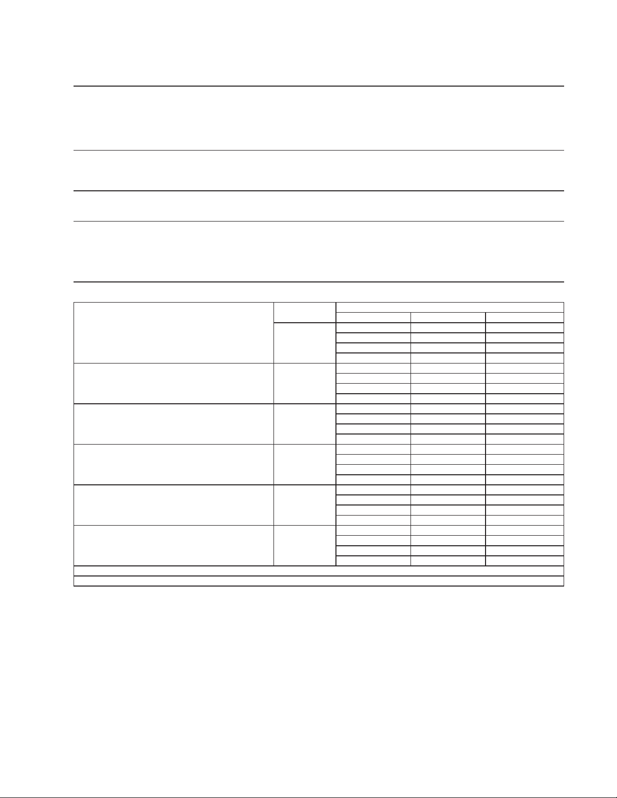
105
27a. F-1501MRJ
Specification Shee
t
A
C SUPPLY VOLTAGE 208-230/60/1
(
3 wire with neutral for 115V
)
COMPRESSOR 208-230 V 9.3 RLA 56 LRA
GEAR MOTOR 115 V 5.6 FLA 400W
CABINET FAN MOTOR 115 V 0.51 FLA 8W
FAN MOTOR 115 V 3.0 A MAX.
OTHER 115 V 0.03 A
MAXIMUM FUSE SIZE 20
A
MAX. HACR BREAKER
(
USA ONLY
)
20
A
MAX. CIRC. BREAKER
(
CANADA ONLY
)
20
A
MINIMUM CIRCUIT AMPACIT
Y
20
A
ELECTRIC & WATER CONSUMPTION
90/70°F 70/50°F
ELECTRIC W
(
kWH/100 lbs.
)
2015 (3.44) 2010 (2.74)
POTABLE WATER
g
al./24HR
(g
al./100 lbs.
)
164 (12.0) 205 (12.0)
SHAPE OF ICE Flake
ICE HARDNESS
App
rox. 66.8%, Ice
(
90/70°F, Conductivit
y
200
µ
s/cm
)
BIN CONTROL SYSTEM Photoelectric Senso
r
CONDENSER
A
ir-Cooled Remote Condenser URC14-F Recommende
d
REFRIGERANT CHARGE R404A, 9 lb. 9 oz.
(
4340
g)
Ice Maker: 5 lb. 2.5 oz.
(
2340
g)
, Cond. Unit: 4 lb. 6.5 oz.
(
2000
g)
Performance Data Shee
t
A
PPROXIMATE
A
mbien
t
ICE PRODUCTION Tem
p
. °F
(
°C
)
PER 24 HR.
70 (21)
1705
(
773
)
1688
(
766
)
1621
(
735
)
80 (26)
1556
(
706
)
1494
(
678
)
1434
(
650
)
90 (32)
1377
(
624
)
1370
(
621
)
1269
(
576
)
lbs./da
y (
k
g
/da
y)
100 (38)
1218
(
553
)
1170
(
531
)
1070
(
485
)
A
PPROXIMATE ELECTRIC
70 (21)
2010 -
-
2011 -
-
2011 -
-
CONSUMPTION
80 (26)
2012 -
-
2013 -
-
2014 -
-
90 (32)
2014 -
-
2015 -
-
2021 -
-
watts
100 (38)
2028 -
-
2034 -
-
2040 -
-
A
PPROXIMATE WATER
70 (21)
205
(
775
)
203
(
767
)
195
(
736
)
CONSUMPTION PER 24 HR.
80 (26)
187
(
707
)
179
(
679
)
172
(
652
)
(
TOTAL
)
90 (32)
165
(
626
)
164
(
623
)
152
(
577
)
g
al. / da
y (
l/da
y)
100 (38)
146
(
554
)
140
(
532
)
128
(
486
)
EVAPORATOR OUTLET TEMP.
70 (21)
19
(
(
-7
)
)
20
(
(
-7
)
)
20
(
(
-7
)
)
°F
(
°C
)
80 (26)
20
(
(
-7
)
)
20
(
(
-6
)
)
21
(
(
-6
)
)
90 (32)
21
(
(
-6
)
)
21
(
(
-6
)
)
22
(
(
-6
)
)
100 (38)
22
(
(
-6
)
)
23
(
(
-5
)
)
23
(
(
-5
)
)
HEAD PRESSURE
70 (21)
215
(
15.1
)
219
(
15.4
)
222
(
15.6
)
80 (26)
226
(
15.9
)
229
(
16.1
)
233
(
16.4
)
90 (32)
236
(
16.6
)
240
(
16.9
)
249
(
17.5
)
PSIG
(
k
g
/cm
2
G
)
100 (38)
258
(
18.1
)
266
(
18.7
)
275
(
19.3
)
SUCTION PRESSURE
70 (21)
38
(
2.7
)
38
(
2.7
)
39
(
2.7
)
PSIG
(
k
g
/cm
2
G
)
80 (26)
39
(
2.7
)
39
(
2.8
)
39
(
2.8
)
90 (32)
40
(
2.8
)
40
(
2.8
)
41
(
2.8
)
100 (38)
41
(
2.9
)
42
(
2.9
)
42
(
3.0
)
BTU/h
(
AT 90°F / WT 70°F
)
BTU/h
(
AT 90°F / WT 70°F
)
HEAT OF REJECTION FROM CONDENSER 12,300
HEAT OF REJECTION FROM COMPRESSOR 1,900
Water Temp. °F (°C)
50 (10) 70 (21) 90 (32)
ENG F-013.0.1196
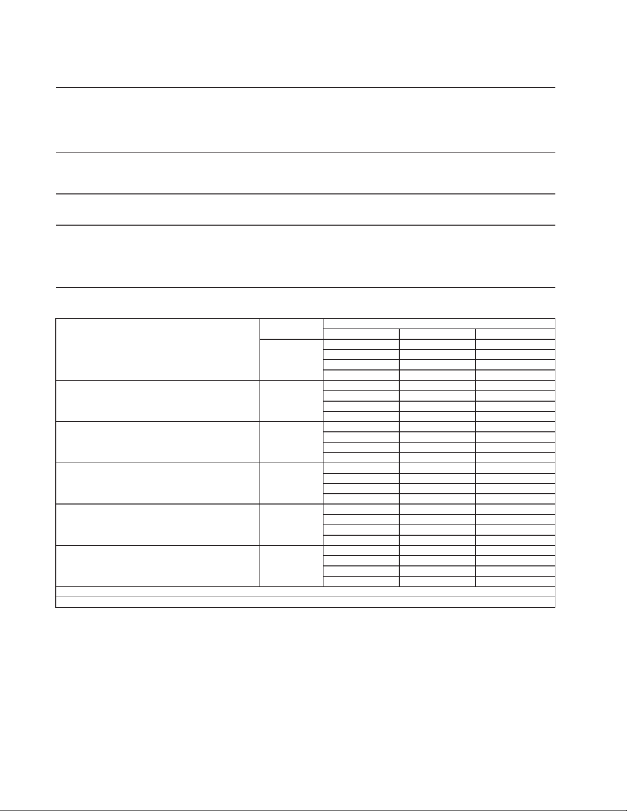
106
27b. F-1501MRJ-C
Specification Shee
t
A
C SUPPLY VOLTAGE 208-230/60/1
(
3 wire with neutral for 115V
)
COMPRESSOR 208-230 V 9.3 RLA 56 LRA
GEAR MOTOR 115 V 5.6 FLA 400W
CABINET FAN MOTOR 115 V 0.51 FLA 8W
FAN MOTOR 115 V 3.0 A MAX.
OTHER 115 V 0.03 A
MAXIMUM FUSE SIZE 20
A
MAX. HACR BREAKER
(
USA ONLY
)
20
A
MAX. CIRC. BREAKER
(
CANADA ONLY
)
20
A
MINIMUM CIRCUIT AMPACIT
Y
20
A
ELECTRIC & WATER CONSUMPTION
90/70°F 70/50°F
ELECTRIC W
(
kWH/100 lbs.
)
2015 (4.35) 2010 (3.50)
POTABLE WATER
g
al./24HR
(g
al./100 lbs.
)
135 (12.0) 160 (12.0)
SHAPE OF ICE Cubele
t
ICE HARDNESS
App
rox. 86.7%, Ice
(
90/70°F, Conductivit
y
200
µ
s/cm
)
BIN CONTROL SYSTEM Photoelectric Senso
r
CONDENSER
A
ir-Cooled Remote Condenser URC14-F Recommende
d
REFRIGERANT CHARGE
R404A, 9 lb. 9 oz. (4340g
)
Ice Maker: 5 lb. 2.5 oz. (2340g), Cond. Unit: 4 lb. 6.5 oz. (2000g)
Performance Data Shee
t
A
PPROXIMATE
A
mbien
t
ICE PRODUCTION Tem
p
. °F
(
°C
)
PER 24 HR.
70 (21)
1335
(
606
)
1324
(
601
)
1282
(
582
)
80 (26)
1242
(
563
)
1203
(
546
)
1165
(
528
)
90 (32)
1128
(
512
)
1125
(
510
)
1058
(
480
)
lbs./da
y (
k
g
/da
y)
100 (38)
1024
(
465
)
992
(
450
)
925
(
420
)
A
PPROXIMATE ELECTRIC
70 (21)
2010 -
-
2011 -
-
2011 -
-
CONSUMPTION
80 (26)
2012 -
-
2013 -
-
2014 -
-
90 (32)
2014 -
-
2015 -
-
2021 -
-
watts
100 (38)
2028 -
-
2034 -
-
2040 -
-
A
PPROXIMATE WATER
70 (21)
160
(
607
)
159
(
602
)
154
(
583
)
CONSUMPTION PER 24 HR.
80 (26)
149
(
564
)
144
(
547
)
140
(
529
)
(
TOTAL
)
90 (32)
135
(
513
)
135
(
511
)
127
(
481
)
g
al. / da
y (
l/da
y)
100 (38)
123
(
466
)
119
(
451
)
111
(
420
)
EVAPORATOR OUTLET TEMP.
70 (21)
19
(
(
-7
)
)
20
(
(
-7
)
)
20
(
(
-7
)
)
°F
(
°C
)
80 (26)
20
(
(
-7
)
)
20
(
(
-6
)
)
21
(
(
-6
)
)
90 (32)
21
(
(
-6
)
)
21
(
(
-6
)
)
22
(
(
-6
)
)
100 (38)
22
(
(
-6
)
)
23
(
(
-5
)
)
23
(
(
-5
)
)
HEAD PRESSURE
70 (21)
215
(
15.1
)
219
(
15.4
)
222
(
15.6
)
80 (26)
226
(
15.9
)
229
(
16.1
)
233
(
16.4
)
90 (32)
236
(
16.6
)
240
(
16.9
)
249
(
17.5
)
PSIG
(
k
g
/cm
2
G
)
100 (38)
258
(
18.1
)
266
(
18.7
)
275
(
19.3
)
SUCTION PRESSURE
70 (21)
38
(
2.7
)
38
(
2.7
)
39
(
2.7
)
PSIG
(
k
g
/cm
2
G
)
80 (26)
39
(
2.7
)
39
(
2.8
)
39
(
2.8
)
90 (32)
40
(
2.8
)
40
(
2.8
)
41
(
2.8
)
100 (38)
41
(
2.9
)
42
(
2.9
)
42
(
3.0
)
BTU/h
(
AT 90°F / WT 70°F
)
BTU/h
(
AT 90°F / WT 70°F
)
HEAT OF REJECTION FROM CONDENSER 12,300
HEAT OF REJECTION FROM COMPRESSOR 1,900
Water Temp. °F (°C)
50 (10) 70 (21) 90 (32)
ENG F-013.0.1196
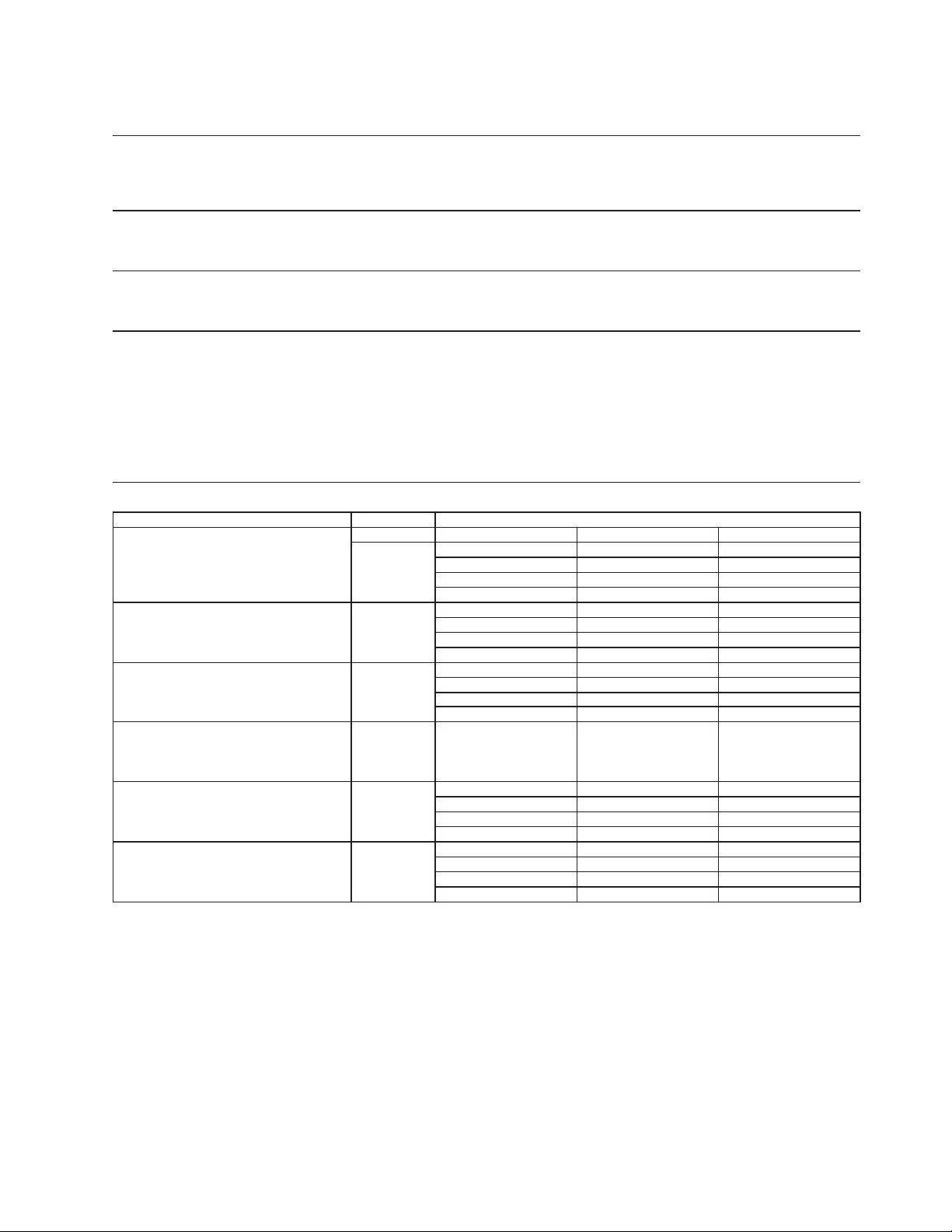
107
28a. F-2001MLJ
Specification Sheet
AC SUPPLY VOLTAGE 115/60/1
COMPRESSOR N/A
GEAR MOTOR 120 V 5.6 FLA 400W
FAN MOTOR 115 V 0.51 FLA 8W
OTHER 120 V 0.03A
MAXIMUM FUSE SIZE 15 A
MAX. HACR BREAKER (USA ONLY) 15 A
MAX. CIRC. BREAKER (CANADA ONLY) 15 A
MINIMUM CIRCUIT AMPACITY 15 A
ELECTRIC & WATER CONSUMPTION 90/70°F 70/50°F
ELECTRIC W (kWH/100 lbs.) 470 (0.6) 490 (0.5)
POTABLE WATER 207 (12) 258 (12)
gal./24HR (gal./100 lbs.)
SHAPE OF ICE Flake
ICE HARDNESS Approx. 69.20%, Ice (32/21 (90/70), Conductivity 200 µs/cm)
BIN CONTROL SYSTEM Photoelectric Sensor
CONDENSING UNIT
REFRIGERANT CHARGE Nitrogen Holding Charge (5 PSIG)
Can be used with refrigerant R404A, R407A, and R407F
Performance Data Sheet
APPROXIMATE Ambient Water Temp. (F)
ICE PRODUCTION Temp. (F)
PER 24 HR. 70 2280 (921) 1955 (887) 1915 (869)
80 2010 (851) 1835 (832) 1795 (814)
90 1760 (798) 1733 (786) 1685 (764)
lbs./DAY ( kg/day) 100 1650 (748) 1615 (733) 1370 (680)
APPROXIMATE ELECTRIC 70 490 -- 470 -- 470 --
CONSUMPTION 80 490 -- 470 -- 470 --
90 490 -- 470 -- 470 --
watts 100 490 -- 470 -- 470 --
APPROXIMATE WATER 70 258 (921) 234 (887) 230 (869)
CONSUMPTION PER 24 HR. 80 225 (851) 220 (832) 215 (814)
(TOTAL) 90 211 (798) 207 (785) 202 (764)
gal. / day (m
3
/day)
100 198 (748) 194 (733) 180 (680)
EVAPORATOR OUTLET TEMP. 70 12 (-11) 12 (-11) 12 (-11)
°F (°C) 80 12 (-11) 12 (-11) 12 (-11)
90 12 (-11) 12 (-11) 14 (-10)
100 14 (-10) 14 (-10) 14 (-10)
HEAD PRESSURE 70 190 (18.4) 256 (18.5) 297 (18.6)
80 190 (18.4) 256 (18.5) 297 (18.6)
90 190 (18.4) 256 (18.5) 297 (18.6)
PSIG (kg/sq.cmG) 100 190 (18.4) 256 (18.5) 297 (18.6)
SUCTION PRESSURE 70 16 (1.8) 21 (1.9) 22 (2.0)
PSIG (kg/sq.cmG) 80 16 (1.8) 21 (1.9) 22 (2.0)
90 16 (1.8) 21 (1.9) 22 (2.0)
100 16 (1.8) 21 (1.9) 22 (2.0)
Required refrigeration capacity for ice maker is estiamted at
11,600BTU/h. Suction pressure need to be set to:
R404A - 22PSIG
R407A - 14PSIG
R407F - 15PSIG
50 70 90
ENG.F-011.1.0205
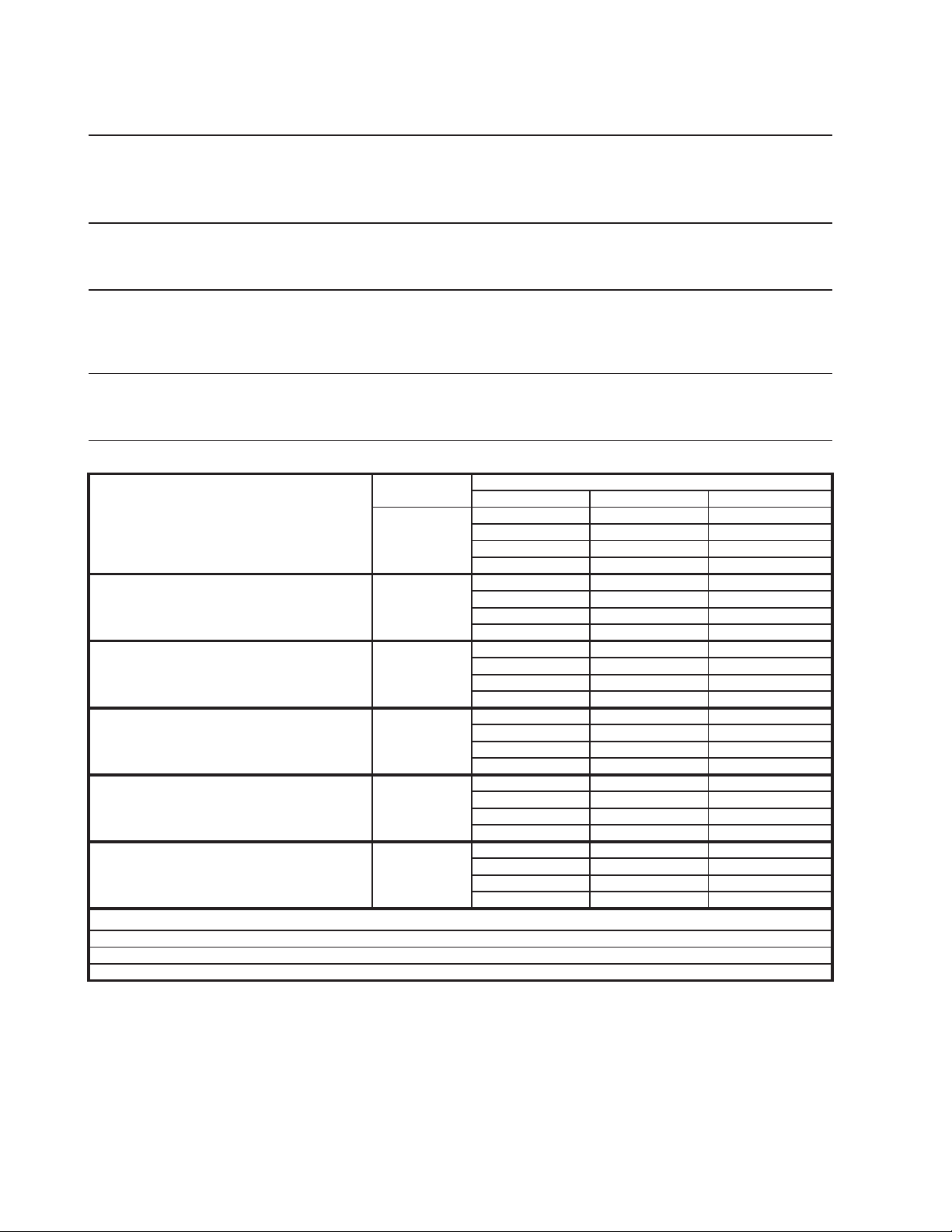
108
28b. F-2001MWJ
S
p
ecification Shee
t
AC SUPPLY VOLTAGE 208-230/60/1
(
3 wire with neutral for 115V
)
COMPRESSOR 208-230 V 10.8 RLA 96 LRA
GEAR MOTOR 120 V 5.6 FLA 400W
FAN MOTOR -
OTHER 120 V 0.03 A
MAXIMUM FUSE SIZE 30
A
MAX. HACR BREAKER
(
USA ONLY
)
30
A
MAX. CIRC. BREAKER
(
CANADA ONLY
)
30
A
MINIMUM CIRCUIT AMPACITY 30
A
ELECTRIC & WATER CONSUMPTION 90/70°F 70/50°F
ELECTRIC W (kWH/100 lbs.) 2409 (3.19
)
2380 (2.82
)
POTABLE WATER 221 (12.0) 245 12.0
)
WATER-COOLED CONDENSER 1895 (109.0
)
1426 (65.3
)
gal./24HR (gal./100 lbs.
)
SHAPE OF ICE Flake
ICE HARDNESS A
pp
rox. 77.0%, Ice
(
32/21
(
90/70
)
, Conductivit
y
200
µ
s/cm
)
BIN CONTROL SYSTEM Photoelectric Senso
r
REFRIGERANT CHARGE R404A, 2 lb. 0.1 oz.
(
910
g)
Performance Data Shee
t
APPROXIMATE Ambien
t
ICE PRODUCTION Tem
p
. °F
(
°C
)
PER 24 HR.
70 (21)
* 2043
(
927
)
2062
(
935
)
2006
(
910
)
80 (26)
1952
(
885
)
1899
(
861
)
1847
(
838
)
90 (32)
1797
(
815
)
* 1840
(
835
)
1701
(
772
)
lbs./da
y (
k
g
/da
y)
100 (38)
1655
(
751
)
1610
(
730
)
* 1472
(
668
)
APPROXIMATE ELECTRIC
70 (21)
* 2380 -- 2384 -- 2389 --
CONSUMPTION
80 (26)
2393 -- 2397 -- 2401 --
90 (32)
2405 -- * 2409 -- 2426 --
watts
100 (38)
2443 -- 2459 -- * 2476 --
APPROXIMATE WATER
70 (21)
* 1671
(
6324
)
2142
(
8109
)
3151
(
11928
)
CONSUMPTION PER 24 HR.
80 (26)
1660
(
6283
)
2123
(
8035
)
3132
(
11856
)
(
TOTAL
)
90 (32)
1641
(
6213
)
* 2116
(
8008
)
3115
(
11789
)
g
al. / da
y (
l/da
y)
100 (38)
1624
(
6148
)
2088
(
7904
)
* 3087
(
11685
)
EVAPORATOR OUTLET TEMP.
70 (21)
* 29
(
(
-2
)
)
25
(
(
-4
)
)
21
(
(
-6
)
)
°F
(
°C
)
80 (26)
17
(
(
-8
)
)
13
(
(
-10
)
)
9
(
(
-13
)
)
90 (32)
5
(
(
-15
)
)
*1
(
(
-17
)
)
3
(
(
-16
)
)
100 (38)
6
(
(
-15
)
)
8
(
(
-13
)
)
* 10
(
(
-12
)
)
HEAD PRESSURE
70 (21)
* 213
(
15.0
)
214
(
15.0
)
215
(
15.1
)
80 (26)
216
(
15.2
)
217
(
15.2
)
218
(
15.3
)
90 (32)
219
(
15.4
)
* 220
(
15.4
)
229
(
16.1
)
PSIG
(
k
g
/cm
2
G
)
100 (38)
239
(
16.8
)
249
(
17.5
)
* 258
(
18.1
)
SUCTION PRESSURE
70 (21)
* 23
(
1.6
)
23
(
1.6
)
23
(
1.6
)
PSIG
(
k
g
/cm
2
G
)
80 (26)
24
(
1.7
)
24
(
1.7
)
24
(
1.7
)
90 (32)
24
(
1.7
)
* 24
(
1.7
)
25
(
1.7
)
100 (38)
26
(
1.8
)
26
(
1.8
)
* 27
(
1.9
)
79 gal/h (AT 90°F / WT 70°F)
Less than 10 PSI
G
BTU/h
(
AT 90°F / WT 70°F
)
BTU/h
(
AT 90°F / WT 70°F
)
WATER FLOW FOR CONDENSER
PRESSURE DROP OF COOLING WATER LINE
HEAT OF REJECTION FROM CONDENSER 19,500
HEAT OF REJECTION FROM COMPRESSOR 2,800
Water Temp. °F (°C)
50 (10) 70 (21) 90 (32)
ENG F-013.0.1196
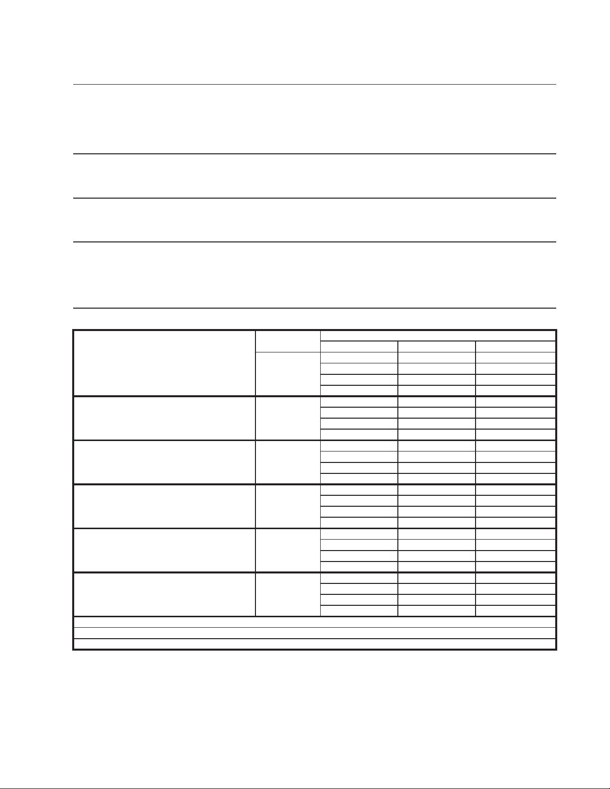
109
28c. F-2001MRJ
S
p
ecification Sheet
AC SUPPLY VOLTAGE 208-230/60/1
(
3 wire with neutral for 115V
)
COMPRESSOR 208-230 V 10.8 RLA 96 LRA
GEAR MOTOR 115 V 5.6 FLA 400W
CABINET FAN MOTOR 115 V 0.51 FLA 8W
FAN MOTOR 115 V 3.0 A MAX.
OTHER 115 V 0.03 A
MAXIMUM FUSE SIZE 30 A
MAX. HACR BREAKER
(
USA ONLY
)
30 A
MAX. CIRC. BREAKER
(
CANADA ONLY
)
30 A
MINIMUM CIRCUIT AMPACIT
Y
30 A
ELECTRIC & WATER CONSUMPTION 90/70°F 70/50°F
ELECTRIC W
(
kWH/100 lbs.
)
3073
(
3.81
)
2576
(
3.30
)
POTABLE WATER 199
(
12.0
)
249
(
12.0
)
g
al./24HR
(g
al./100 lbs.
)
SHAPE OF ICE Flake
ICE HARDNESS A
pp
rox. 78.0%, Ice
(
32/21
(
90/70
)
, Conductivit
y
200
µ
s/cm
)
BIN CONTROL SYSTEM Photoelectric Sensor
CONDENSE
R
Air-cooled remote condenser, URC-22F
REFRIGERANT CHARGE R404A, 15 lb. 14 oz.
(
7200
g)
Ice Maker: 8 lb. 2.5 oz.
(
3700
g)
, Cond. Unit: 7 lb. 11.5 oz.
(
3500
g)
Performance Data Sheet
APPROXIMATE Ambient
ICE PRODUCTION Tem
p
. °F
(
°C
)
PER 24 HR.
70 (21)
* 2073
(
940
)
2038
(
924
)
1963
(
890
)
80 (26)
1890
(
857
)
1820
(
825
)
1752
(
795
)
90 (32)
1688
(
765
)
* 1660
(
753
)
1565
(
710
)
lbs./da
y (
k
g
/da
y)
100 (38)
1507
(
684
)
1451
(
658
)
* 1356
(
615
)
APPROXIMATE ELECTRIC
70 (21)
* 2576 -
-
2647 -
-
2718 -
-
CONSUMPTION
80 (26)
2789 -
-
2860 -
-
2931 -
-
90 (32)
3002 -
-
* 3073 -
-
2991 -
-
watts
100 (38)
2908 -
-
2826 -
-
* 2743 -
-
APPROXIMATE WATER
70 (21)
* 249
(
942
)
245
(
926
)
236
(
892
)
CONSUMPTION PER 24 HR.
80 (26)
227
(
859
)
219
(
827
)
210
(
796
)
(
TOTAL
)
90 (32)
203
(
767
)
* 199
(
754
)
188
(
711
)
g
al. / da
y (
l/da
y)
100 (38)
181
(
685
)
174
(
659
)
* 163
(
616
)
EVAPORATOR OUTLET TEMP.
70 (21)
*5
(
(
-15
)
)
6
(
(
-15
)
)
7
(
(
-14
)
)
°F
(
°C
)
80 (26)
7
(
(
-14
)
)
8
(
(
-13
)
)
9
(
(
-13
)
)
90 (32)
10
(
(
-12
)
)
* 10
(
(
-12
)
)
11
(
(
-12
)
)
100 (38)
12
(
(
-11
)
)
13
(
(
-11
)
)
* 14
(
(
-10
)
)
HEAD PRESSURE
70 (21)
* 198
(
13.9
)
203
(
14.3
)
209
(
14.7
)
80 (26)
214
(
15.0
)
219
(
15.4
)
224
(
15.8
)
90 (32)
230
(
16.1
)
* 235
(
16.5
)
243
(
17.1
)
PSIG
(
k
g
/cm
2
G
)
100 (38)
252
(
17.7
)
260
(
18.3
)
* 268
(
18.8
)
SUCTION PRESSURE
70 (21)
* 19
(
1.3
)
19
(
1.4
)
20
(
1.4
)
PSIG
(
k
g
/cm
2
G
)
80 (26)
20
(
1.4
)
20
(
1.4
)
20
(
1.4
)
90 (32)
21
(
1.5
)
* 21
(
1.5
)
23
(
1.6
)
100 (38)
25
(
1.7
)
26
(
1.8
)
* 28
(
2.0
)
in
3
BTU/h
(
AT 90°F / WT 70°F
)
BTU/h
(
AT 90°F / WT 70°F
)
Water Temp. °F (°C)
50 (10) 70 (21) 90 (32)
HEAT OF REJECTION FROM COMPRESSOR 2,600
CONDENSER VOLUME 214
HEAT OF REJECTION FROM CONDENSER 16,500
ENG F-013.0.1196
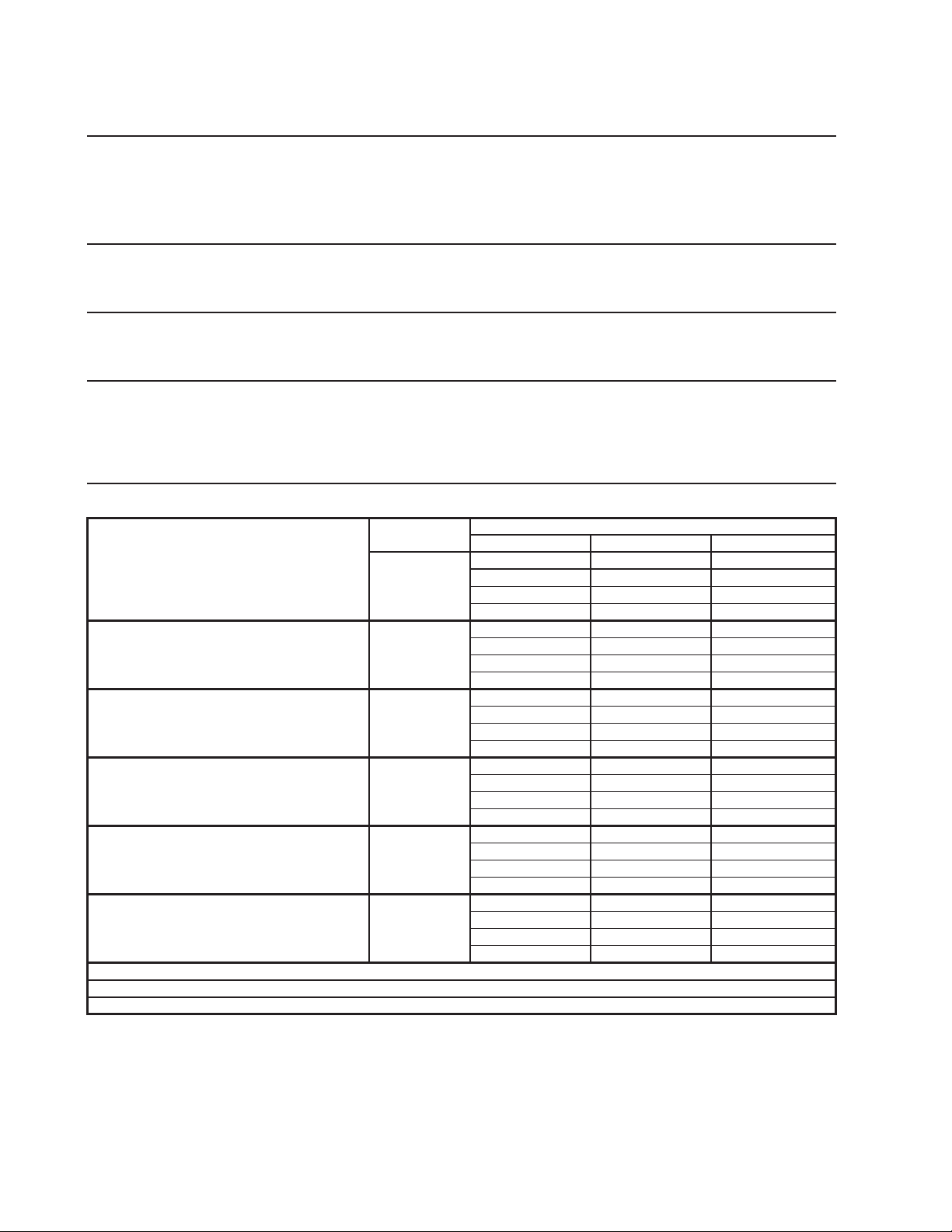
110
28d. F-2001MRJ-C
S
p
ecification Sheet
AC SUPPLY VOLTAGE 208-230/60/1
(
3 wire with neutral for 115V
)
COMPRESSOR 208-230 V 10.8 RLA 96 LRA
GEAR MOTOR 115 V 5.6 FLA 400W
CABINET FAN MOTOR 115 V 0.51 FLA 8W
FAN MOTOR 115 V 3.0 A MAX.
OTHER 115 V 0.03 A
MAXIMUM FUSE SIZE 30 A
MAX. HACR BREAKER
(
USA ONLY
)
30 A
MAX. CIRC. BREAKER
(
CANADA ONLY
)
30 A
MINIMUM CIRCUIT AMPACIT
Y
30 A
ELECTRIC & WATER CONSUMPTION 90/70°F 70/50°F
ELECTRIC W (kWH/100 lbs.) 2684 (4.35) 2687 (3.52)
POTABLE WATER 180 (12.0) 220 (12.0)
gal./24HR (gal./100 lbs.)
SHAPE OF ICE Cublete
ICE HARDNESS A
pp
rox. 90.0%, Ice
(
32/21
(
90/70
)
, Conductivit
y
200
µ
s/cm
)
BIN CONTROL SYSTEM Photoelectric Sensor
CONDENSE
R
Air-cooled remote condenser, URC-22F
REFRIGERANT CHARGE R404A, 15 lb. 14 oz. (7200g)
Ice Maker: 8 lb. 2.5 oz. (3700g), Cond. Unit: 7 lb. 11.5 oz. (3500g)
Performance Data Sheet
APPROXIMATE Ambient
ICE PRODUCTION Tem
p
. °F
(
°C
)
PER 24 HR.
70 (21)
* 1832
(
831
)
1810
(
821
)
1746
(
792
)
80 (26)
1685
(
764
)
1625
(
737
)
1568
(
711
)
90 (32)
1513
(
686
)
* 1500
(
680
)
1409
(
639
)
lbs./da
y (
k
g
/da
y)
100 (38)
1359
(
616
)
1311
(
595
)
* 1220
(
553
)
APPROXIMATE ELECTRIC
70 (21)
* 2687 -
-
2687 -
-
2686 -
-
CONSUMPTION
80 (26)
2686 -
-
2685 -
-
2685 -
-
90 (32)
2684 -
-
* 2684 -
-
2716 -
-
watts
100 (38)
2747 -
-
2779 -
-
* 2810 -
-
APPROXIMATE WATER
70 (21)
* 220
(
833
)
217
(
822
)
210
(
794
)
CONSUMPTION PER 24 HR.
80 (26)
202
(
766
)
195
(
739
)
188
(
713
)
(
TOTAL
)
90 (32)
182
(
688
)
* 180
(
682
)
169
(
640
)
g
al. / da
y (
l/da
y)
100 (38)
163
(
618
)
157
(
596
)
* 146
(
554
)
EVAPORATOR OUTLET TEMP.
70 (21)
*5
(
(
-15
)
)
6
(
(
-15
)
)
6
(
(
-14
)
)
°F
(
°C
)
80 (26)
7
(
(
-14
)
)
7
(
(
-14
)
)
8
(
(
-14
)
)
90 (32)
8
(
(
-13
)
)
*9
(
(
-13
)
)
10
(
(
-13
)
)
100 (38)
10
(
(
-12
)
)
11
(
(
-12
)
)
* 12
(
(
-11
)
)
HEAD PRESSURE
70 (21)
* 194
(
13.6
)
200
(
14.1
)
206
(
14.5
)
80 (26)
212
(
14.9
)
218
(
15.3
)
224
(
15.7
)
90 (32)
230
(
16.2
)
* 236
(
16.6
)
246
(
17.3
)
PSIG
(
k
g
/cm
2
G
)
100 (38)
256
(
18.0
)
265
(
18.6
)
* 275
(
19.3
)
SUCTION PRESSURE
70 (21)
* 23
(
1.6
)
24
(
1.7
)
24
(
1.7
)
PSIG
(
k
g
/cm
2
G
)
80 (26)
25
(
1.7
)
25
(
1.8
)
26
(
1.8
)
90 (32)
26
(
1.9
)
* 27
(
1.9
)
28
(
2.0
)
100 (38)
29
(
2.0
)
29
(
2.1
)
* 30
(
2.1
)
in
3
BTU/h
(
AT 90°F / WT 70°F
)
BTU/h
(
AT 90°F / WT 70°F
)
CONDENSER VOLUME 214
HEAT OF REJECTION FROM CONDENSER 20,300
HEAT OF REJECTION FROM COMPRESSOR 2,900
Water Temp. °F (°C)
50 (10) 70 (21) 90 (32)
ENG F-013.0.1196

111
28e. F-2001MRJ3
S
p
ecification Sheet
AC SUPPLY VOLTAGE 208-230/60/3
COMPRESSOR 208-230 V 9.0 RLA 96 LRA
GEAR MOTOR 115 V 5.6 FLA 400W
CABINET FAN MOTOR 115 V 0.51 FLA 8W
FAN MOTOR 115 V 3.0 A MAX.
OTHER 115 V 0.03 A
MAXIMUM FUSE SIZE 20 A
MAX. HACR BREAKER
(
USA ONLY
)
20 A
MAX. CIRC. BREAKER
(
CANADA ONLY
)
20 A
MINIMUM CIRCUIT AMPACIT
Y
20 A
ELECTRIC & WATER CONSUMPTION 90/70°F 70/50°F
ELECTRIC W
(
kWH/100 lbs.
)
2681
(
3.90
)
2590
(
3.00
)
POTABLE WATER 201
(
12.0
)
252
(
12.0
)
g
al./24HR
(g
al./100 lbs.
)
SHAPE OF ICE Flake
ICE HARDNESS A
pp
rox. 77.0%, Ice
(
32/21
(
90/70
)
, Conductivit
y
200
µ
s/cm
)
BIN CONTROL SYSTEM Photoelectric Sensor
CONDENSE
R
Air-cooled remote condenser, URC-22F
REFRIGERANT CHARGE R404A, 15 lb. 14 oz.
(
7200
g)
Ice Maker: 8 lb. 2.5 oz.
(
3700
g)
, Cond. Unit: 7 lb. 11.5 oz.
(
3500
g)
Performance Data Sheet
APPROXIMATE Ambient
ICE PRODUCTION Tem
p
. °F
(
°C
)
PER 24 HR.
70 (21)
* 2098
(
952
)
2070
(
939
)
1988
(
902
)
80 (26)
1910
(
866
)
1835
(
832
)
1762
(
799
)
90 (32)
1693
(
768
)
* 1675
(
760
)
1562
(
709
)
lbs./da
y (
k
g
/da
y)
100 (38)
1501
(
681
)
1442
(
654
)
* 1330
(
603
)
APPROXIMATE ELECTRIC
70 (21)
* 2590 -
-
2603 -
-
2616 -
-
CONSUMPTION
80 (26)
2629 -
-
2642 -
-
2655 -
-
90 (32)
2668 -
-
* 2681 -
-
2698 -
-
watts
100 (38)
2714 -
-
2731 -
-
* 2747 -
-
APPROXIMATE WATER
70 (21)
* 252
(
953
)
248
(
941
)
239
(
904
)
CONSUMPTION PER 24 HR.
80 (26)
229
(
868
)
220
(
834
)
212
(
801
)
(
TOTAL
)
90 (32)
203
(
769
)
* 201
(
761
)
188
(
710
)
g
al. / da
y (
l/da
y)
100 (38)
180
(
682
)
173
(
655
)
* 160
(
605
)
EVAPORATOR OUTLET TEMP.
70 (21)
*2
(
(
-17
)
)
2
(
(
-17
)
)
3
(
(
-16
)
)
°F
(
°C
)
80 (26)
3
(
(
-16
)
)
3
(
(
-16
)
)
3
(
(
-16
)
)
90 (32)
4
(
(
-16
)
)
*4
(
(
-16
)
)
5
(
(
-15
)
)
100 (38)
7
(
(
-14
)
)
8
(
(
-13
)
)
* 10
(
(
-12
)
)
HEAD PRESSURE
70 (21)
* 198
(
13.9
)
203
(
14.3
)
208
(
14.6
)
80 (26)
213
(
14.9
)
218
(
15.3
)
222
(
15.6
)
90 (32)
227
(
16.0
)
* 232
(
16.3
)
243
(
17.1
)
PSIG
(
k
g
/cm
2
G
)
100 (38)
254
(
17.8
)
264
(
18.6
)
* 275
(
19.3
)
SUCTION PRESSURE
70 (21)
* 19
(
1.3
)
20
(
1.4
)
21
(
1.5
)
PSIG
(
k
g
/cm
2
G
)
80 (26)
22
(
1.6
)
23
(
1.6
)
24
(
1.7
)
90 (32)
25
(
1.8
)
* 26
(
1.8
)
27
(
1.9
)
100 (38)
28
(
1.9
)
28
(
2.0
)
* 29
(
2.1
)
in
3
BTU/h
(
AT 90°F / WT 70°F
)
BTU/h
(
AT 90°F / WT 70°F
)
CONDENSER VOLUME 214
HEAT OF REJECTION FROM CONDENSER 19,500
HEAT OF REJECTION FROM COMPRESSOR 2,900
Water Temp. °F (°C)
50 (10) 70 (21) 90 (32)
ENG F-013.0.1196
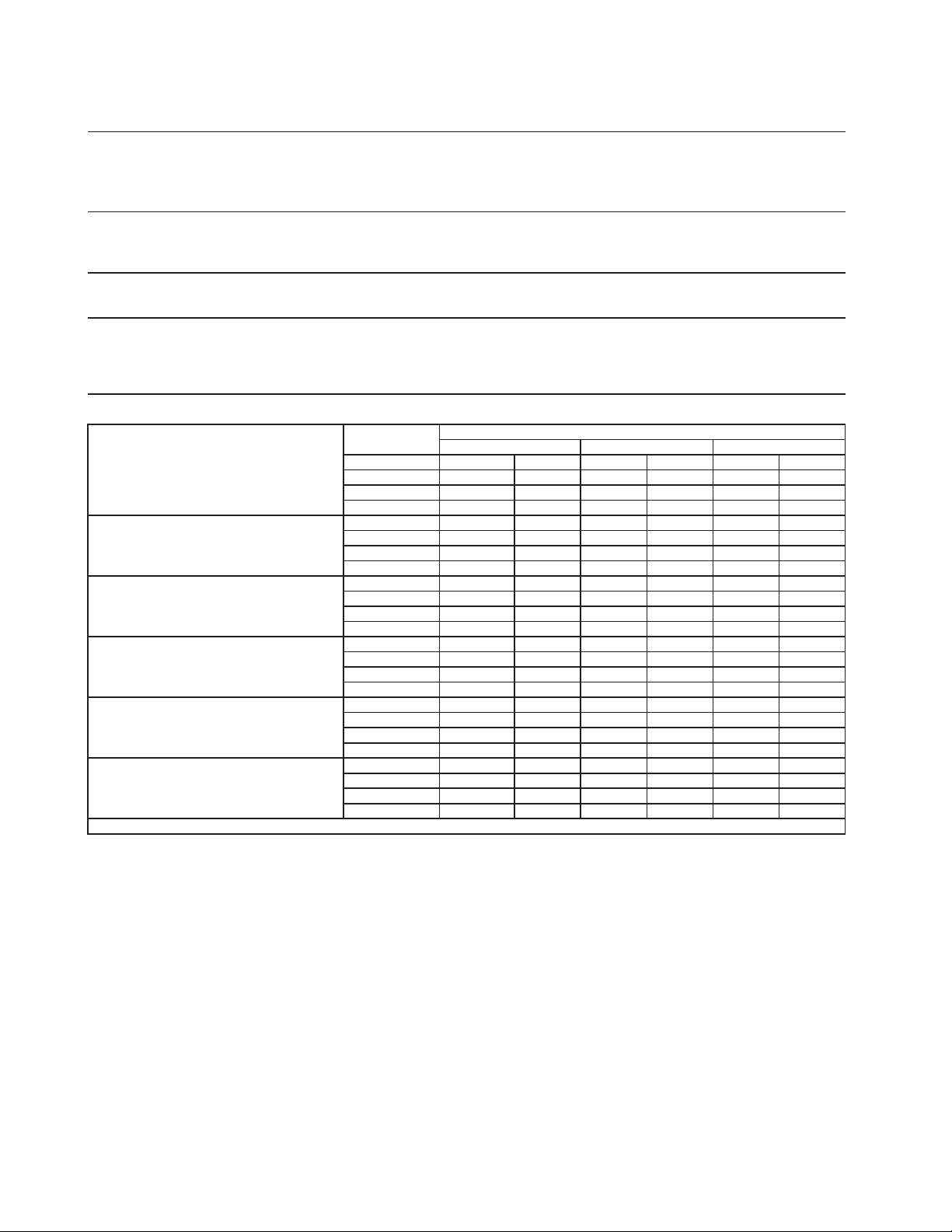
112
29. FD-1001MAJ-C
S
p
ecification Sheet
A
C SUPPLY VOLTAGE 115/60/1
COMPRESSOR 115 V 11.2 RLA 93 LRA
GEAR MOTOR 115 V 3.0 FLA 200 W
FAN MOTOR 115 V 1.0 FLA 1/15 HP
OTHER 120 V 0.03 A
MAXIMUM FUSE SIZ
E
20
A
MAX. HACR BREAKER
(
USA ONLY
)
20
A
MAX. CIRC. BREAKER
(
CANADA ONLY
)
20
A
MINIMUM CIRCUIT AMPACIT
Y
20
A
ELECTRIC & WATER CONSUMPTION 90/70°F 70/50°F
ELECTRIC W
(
kWH/100 lbs.
)
1389
(
4.79
)
1319
(
3.40
)
WATER
g
al./24HR
(g
al./100 lbs.
)
81
(
12.0
)
113
(
12.0
)
SHAPE OF ICE Cubelet
ICE HARDNESS
App
rox. 85.9%, Ice
(
90/70°F, Conductivit
y
200
µ
s/cm
)
BIN CONTROL SYSTEM (PRIMARY) Photoelectric Sensor (BC1 (Infrared Sensor))
BIN CONTROL SYSTEM (SECONDARY) Proximity Switch (BC2 (Mechanical)
)
REFRIGERANT CHARGE R-404A, 2 lb. 4.1 oz.
(
1025
g)
Performance Data Sheet
A
PPROXIMATE
A
mbien
t
ICE PRODUCTION Tem
p
. °F
(
°C
)
PER 24 HR.
70 (21)
940 426 900 408 861 390
80 (26)
823 373 787 357 752 341
90 (32)
719 326 677 307 657 298
lbs./da
y (
k
g
/da
y)
100 (38)
628 285 601 273 580 263
A
PPROXIMATE ELECTRIC
70 (21)
1319 -
-
1329 -
-
1339 -
-
CONSUMPTION
80 (26)
1349 -
-
1359 -
-
1369 -
-
90 (32)
1379 -
-
1389 -
-
1393 -
-
watts
100 (38)
1397 -
-
1400 -
-
1404 -
-
A
PPROXIMATE WATER
70 (21)
113 427 108 409 103 391
CONSUMPTION PER 24 HR.
80 (26)
99 374 94 358 90 342
(
TOTAL
)
90 (32)
86 327 81 308 79 299
g
al. / da
y (
l/da
y)
100 (38)
75 286 72 273 70 264
EVAPORATOR OUTLET TEMP.
70 (21)
12
(
-11
)
12
(
-11
)
13
(
-11
)
°F
(
°C
)
80 (26)
13
(
-11
)
13
(
-10
)
13
(
-10
)
90 (32)
14
(
-10
)
14
(
-10
)
20
(
-10
)
100 (38)
15
(
-10
)
15
(
-9
)
16
(
-9
)
HEAD PRESSURE
70 (21)
204 14.3 213 15.0 223 15.6
80 (26)
232 16.3 241 16.9 250 17.6
90 (32)
260 18.3 269 18.9 278 19.5
PSIG
(
k
g
/cm
2
G
)
100 (38)
287 20.1 295 20.7 304 21.4
SUCTION PRESSURE
70 (21)
31 2.2 32 2.2 32 2.3
PSIG
(
k
g
/cm
2
G
)
80 (26)
33 2.3 34 2.4 35 2.4
90 (32)
35 2.5 36 2.5 37 2.6
100 (38)
38 2.6 38 2.7 39 2.7
8800 BTU/h
(
AT 90°F / WT 70°F
)
TOTAL HEAT OF REJECTION
Water Temp. °F (°C)
50 (10) 70 (21) 90 (32)
ENG F-013.0.1196
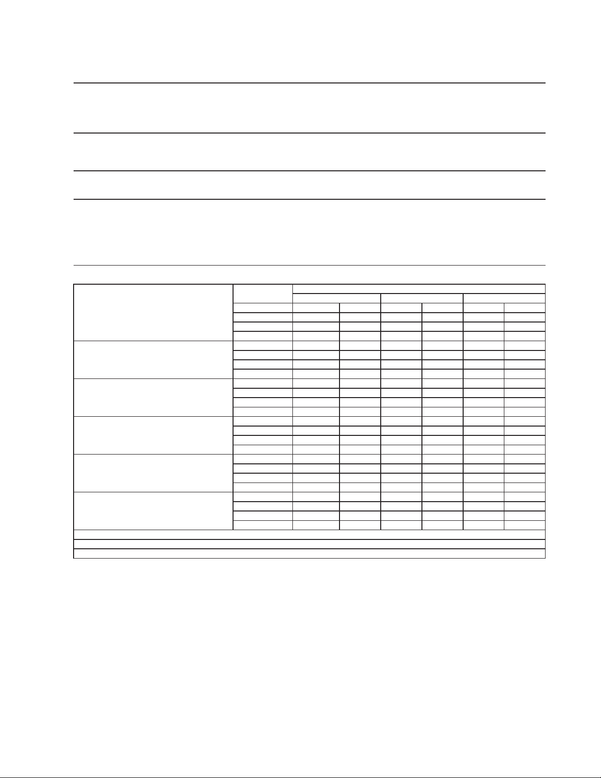
113
30. FD-1001MRJ-C
S
p
ecification Sheet
A
C SUPPLY VOLTAGE 115/60/1
COMPRESSOR 115 V 11.2 RLA 93 LRA
GEAR MOTOR 115 V 3.0 FLA 200 W
FAN MOTOR REMOTE 120 V 1.0 FLA
OTHER 120 V 0.53 A
MAXIMUM FUSE SIZ
E
20
A
MAX. HACR BREAKER
(
USA ONLY
)
20
A
MAX. CIRC. BREAKER
(
CANADA ONLY
)
20
A
MINIMUM CIRCUIT AMPACIT
Y
20
A
ELECTRIC & WATER CONSUMPTION 90/70°F 70/50°F
ELECTRIC W
(
kWH/100 lbs.
)
1440
(
5.08
)
1401
(
3.6
)
WATER
g
al./24HR
(g
al./100 lbs.
)
82
(
12.0
)
112
(
12.0
)
SHAPE OF ICE Cubelet
ICE HARDNESS
App
rox. 81.1%, Ice
(
90/70°F, Conductivit
y
200
µ
s/cm
)
BIN CONTROL SYSTEM (PRIMARY) Photoelectric Sensor (BC1 (Infrared Sensor))
BIN CONTROL SYSTEM (SECONDARY) Proximity Switch (BC2 (Mechanical)
)
CONDENSER
A
ir-Cooled Remote Condenser URC5-F Recommended
REFRIGERANT CHARGE
R-404A, 4 lb. 1.2 oz. (1850 g)
(Ice Maker: 2 lb. 3.2 oz., Cond. Unit: 1 lb. 14 oz. )
Performance Data Sheet
A
PPROXIMATE
A
mbien
t
ICE PRODUCTION Tem
p
. °F
(
°C
)
PER 24 HR.
70 (21)
930 422 895 406 857 389
80 (26)
820 372 785 356 752 341
90 (32)
720 326 683 310 660 299
lbs./da
y (
k
g
/da
y)
100 (38)
631 286 604 274 580 263
A
PPROXIMATE ELECTRIC
70 (21)
1401 -
-
1407 -
-
1412 -
-
CONSUMPTION
80 (26)
1418 -
-
1423 -
-
1429 -
-
90 (32)
1434 -
-
1440 -
-
1443 -
-
watts
100 (38)
1445 -
-
1448 -
-
1450 -
-
A
PPROXIMATE WATER
70 (21)
112 423 107 407 103 389
CONSUMPTION PER 24 HR.
80 (26)
98 373 94 357 90 342
(
TOTAL
)
90 (32)
86 327 82 310 79 300
g
al. / da
y (
l/da
y)
100 (38)
76 287 73 275 70 264
EVAPORATOR OUTLET TEMP.
70 (21)
5
(
-15
)
6
(
-15
)
6
(
-14
)
°F
(
°C
)
80 (26)
7
(
-14
)
7
(
-14
)
8
(
-14
)
90 (32)
8
(
-13
)
9
(
-13
)
20
(
-13
)
100 (38)
10
(
-12
)
11
(
-12
)
12
(
-11
)
HEAD PRESSURE
70 (21)
205 14.4 213 15.0 222 15.6
PSIG
(
k
g
/cm
2
G
)
80 (26)
230 16.2 239 16.8 247 17.4
90 (32)
256 18.0 264 18.6 273 19.2
PSIG
(
k
g
/cm
2
G
)
100 (38)
283 19.9 292 20.5 301 21.2
SUCTION PRESSURE
70 (21)
33 2.3 33 2.3 34 2.4
PSIG
(
k
g
/cm
2
G
)
80 (26)
34 2.4 35 2.4 35 2.5
90 (32)
36 2.5 36 2.5 37 2.6
100 (38)
38 2.6 38 2.7 39 2.7
CONDENSER VOLUME 74.5 cu in
8900 BTU/h
(
AT 90°F / WT 70°F
)
1400 BTU/h
(
AT 90°F / WT 70°F
)
Water Temp. °F (°C)
HEAT OF REJECTION FROM CONDENSER
HEAT OF REJECTION FROM COMPRESSOR
90 (32)70 (21)50 (10)
ENG F-013.0.1196
114
31. FD-1002MAJ-C
Specification Shee
t
AC SUPPLY VOLTAGE 115/60/1
COMPRESSOR 115/60/1 11.2 RLA 93 LRA
GEAR MOTOR 115 V 3.0 FLA 200 W
FAN MOTOR 115 V 1.0 FLA 1/15 HP
OTHER 115 V 0.03 A
MAXIMUM FUSE SIZE 20
A
MAX. HACR BREAKER
(
USA ONLY
)
20
A
MAX. CIRC. BREAKER
(
CANADA ONLY
)
20
A
MINIMUM CIRCUIT AMPACITY 20
A
ELECTRIC & WATER CONSUMPTION
90/70°F 70/50°F
ELECTRIC W
(
kWH/100 lbs.
)
1366 (4.57
)
1301 (3.51
)
WATER
g
al./24HR
(g
al./100 lbs.
)
87 (12.0) 107 (12.0)
SHAPE OF ICE Cubele
t
ICE HARDNESS A
pp
rox. 87.1%, Ice
(
90/70°F, Conductivit
y
200
µ
s/cm
)
BIN CONTROL SYSTEM Photoelectric Senso
r
REFRIGERANT CHARGE
R404A, 2 lb. 4 oz. (1025g
)
Performance Data Shee
t
APPROXIMATE Ambien
t
ICE PRODUCTION Tem
p
. °F
(
°C
)
PER 24 HR.
70 (21)
890
(
404
)
882
(
400
)
849
(
385
)
80 (26)
817
(
371
)
786
(
357
)
757
(
343
)
90 (32)
729
(
331
)
726
(
329
)
675
(
306
)
lbs./da
y (
k
g
/da
y)
100 (38)
650
(
295
)
625
(
284
)
575
(
261
)
APPROXIMATE ELECTRIC
70 (21)
1301
-- 1310 -- 1319 --
CONSUMPTION
80 (26)
1329 -- 1338 -- 1347 --
90 (32)
1356 --
1366
-- 1381 --
watts
100 (38)
1396 -- 1411 --
1426
--
APPROXIMATE WATER
70 (21)
107
(
404
)
106
(
401
)
102
(
386
)
CONSUMPTION PER 24 HR.
80 (26)
98
(
371
)
94
(
357
)
91
(
344
)
(
TOTAL
)
90 (32)
87
(
331
)
87
(
330
)
81
(
307
)
g
al. / da
y (
l/da
y)
100 (38)
78
(
295
)
75
(
284
)
69
(
261
)
EVAPORATOR OUTLET TEMP.
70 (21)
16
(
(
-9
)
)
16
(
(
-9
)
)
16
(
(
-9
)
)
°F
(
°C
)
80 (26)
17
(
(
-9
)
)
17
(
(
-8
)
)
17
(
(
-8
)
)
90 (32)
17
(
(
-8
)
)
18
(
(
-8
)
)
18
(
(
-8
)
)
100 (38)
19
(
(
-8
)
)
19
(
(
-7
)
)
19
(
(
-7
)
)
HEAD PRESSURE
70 (21)
213
(
15.0
)
222
(
15.6
)
231
(
16.2
)
80 (26)
240
(
16.8
)
248
(
17.5
)
257
(
18.1
)
90 (32)
266
(
18.7
)
275
(
19.3
)
285
(
20.0
)
PSIG
(
k
g
/cm
2
G
)
100 (38)
295
(
20.7
)
305
(
21.4
)
315
(
22.1
)
SUCTION PRESSURE
70 (21)
32
(
2.2
)
33
(
2.3
)
34
(
2.4
)
PSIG
(
k
g
/cm
2
G
)
80 (26)
35
(
2.4
)
35
(
2.5
)
36
(
2.5
)
90 (32)
37
(
2.6
)
38
(
2.7
)
39
(
2.7
)
100 (38)
40
(
2.8
)
40
(
2.8
)
41
(
2.9
)
BTU/h
(
AT 90°F / WT 70°F
)
BTU/h
(
AT 90°F / WT 70°F
)
HEAT OF REJECTION FROM CONDENSER 8,700
HEAT OF REJECTION FROM COMPRESSOR 1,400
Water Temp. °F (°C)
50 (10) 70 (21) 90 (32)
ENG F-013.0.1196
115
32. FD-1002MRJ-C
Specification Shee
t
AC SUPPLY VOLTAGE 115/60/1
COMPRESSOR 115/60/1 11.2 RLA 93 LRA
GEAR MOTOR 115 V 3.0 FLA 200 W
FAN MOTOR 115 V 1.0 FLA
OTHER 115 V 0.03 A
MAXIMUM FUSE SIZE 20
A
MAX. HACR BREAKER
(
USA ONLY
)
20
A
MAX. CIRC. BREAKER
(
CANADA ONLY
)
20
A
MINIMUM CIRCUIT AMPACITY 20
A
ELECTRIC & WATER CONSUMPTION
90/70°F 70/50°F
ELECTRIC W
(
kWH/100 lbs.
)
1393 (4.94
)
1333 (3.90
)
WATER
g
al./24HR
(g
al./100 lbs.
)
82 (12.0) 99 (12.0)
SHAPE OF ICE Cubele
t
ICE HARDNESS A
pp
rox. 85.9%, Ice
(
90/70°F, Conductivit
y
200
µ
s/cm
)
BIN CONTROL SYSTEM Photoelectric Senso
r
CONDENSER Air-Cooled Remote Condenser URC5-F Recommende
d
REFRIGERANT CHARGE R404A, 4 lb. 1 oz.
(
1850
g)
Ice Maker: 2 lb. 3.3 oz. (1000g), Cond. Unit: 1 lb. 14 oz. (850g)
Performance Data Shee
t
APPROXIMATE Ambien
t
ICE PRODUCTION Tem
p
. °F
(
°C
)
PER 24 HR.
70 (21)
821
(
372
)
808
(
367
)
783
(
355
)
80 (26)
759
(
344
)
735
(
333
)
712
(
323
)
90 (32)
690
(
313
)
680
(
308
)
648
(
294
)
lbs./da
y (
k
g
/da
y)
100 (38)
627
(
285
)
608
(
276
)
575
(
261
)
APPROXIMATE ELECTRIC
70 (21)
1333
-- 1342 -- 1350 --
CONSUMPTION
80 (26)
1359 -- 1367 -- 1376 --
90 (32)
1384 --
1393
-- 1395 --
watts
100 (38)
1396 -- 1398 --
1400
--
APPROXIMATE WATER
70 (21)
99
(
373
)
97
(
367
)
94
(
356
)
CONSUMPTION PER 24 HR.
80 (26)
91
(
345
)
88
(
334
)
86
(
324
)
(
TOTAL
)
90 (32)
83
(
314
)
82
(
309
)
78
(
294
)
g
al. / da
y (
l/da
y)
100 (38)
75
(
285
)
73
(
276
)
69
(
261
)
EVAPORATOR OUTLET TEMP.
70 (21)
16
(
(
-9
)
)
16
(
(
-9
)
)
16
(
(
-9
)
)
°F
(
°C
)
80 (26)
17
(
(
-9
)
)
17
(
(
-8
)
)
17
(
(
-8
)
)
90 (32)
17
(
(
-8
)
)
18
(
(
-8
)
)
18
(
(
-8
)
)
100 (38)
19
(
(
-8
)
)
19
(
(
-7
)
)
19
(
(
-7
)
)
HEAD PRESSURE
70 (21)
209
(
14.7
)
216
(
15.2
)
223
(
15.7
)
80 (26)
230
(
16.2
)
237
(
16.7
)
244
(
17.2
)
90 (32)
251
(
17.7
)
258
(
18.2
)
268
(
18.8
)
PSIG
(
k
g
/cm
2
G
)
100 (38)
277
(
19.4
)
286
(
20.1
)
295
(
20.7
)
SUCTION PRESSURE
70 (21)
32
(
2.2
)
32
(
2.3
)
33
(
2.3
)
PSIG
(
k
g
/cm
2
G
)
80 (26)
33
(
2.3
)
34
(
2.4
)
34
(
2.4
)
90 (32)
35
(
2.4
)
35
(
2.5
)
36
(
2.5
)
100 (38)
37
(
2.6
)
37
(
2.6
)
38
(
2.7
)
BTU/h
(
AT 90°F / WT 70°F
)
BTU/h
(
AT 90°F / WT 70°F
)
Water Temp. °F (°C)
HEAT OF REJECTION FROM CONDENSER 8,500
HEAT OF REJECTION FROM COMPRESSOR 1,300
50 (10) 70 (21) 90 (32)
ENG F-013.0.1196
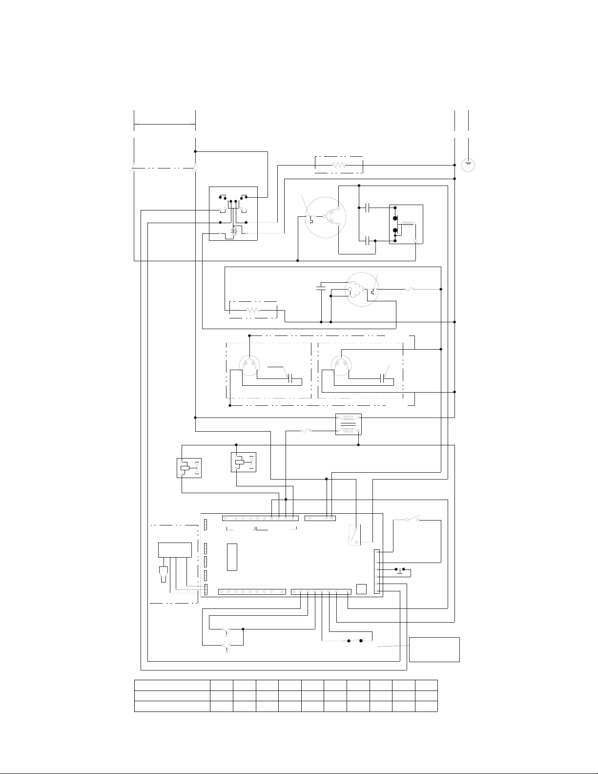
116
B. Wiring Diagrams
1. F-1001MAH(-C), F-1001MWH(-C), F-1001MRH(-C), FD-1001M_H-C
(BR)
(W)
(DBU)
INFRARED
SENSOR
(BK)
WIRE COLOR CODE
BK -BLACK
BR -BROWN
BU -BLUE
DBU -DARK BLUE
GR -GREEN
GY -GRAY
LBU -LIGHT BLUE
O -ORANGE
P -PINK
R -RED
V -VIOLET
W -WHITE
Y -YELLOW
W/BK -WHITE BLACK
W/BR -WHITE BROWN
W/BU -WHITE BLUE
W/O -WHITE ORANGE
W/R -WHITE RED
(T2)
(C)
N
W/O
W/O
O
CAP.
24MFD
GND
S2
S1
X1
115VAC
K9
5VDC
K5
K4
K3
J2
(C)
FUSE (1A)
FUSE
(3A)
L1
W/R
R
LBU
R
CONTROL
TRANSFORMER
Y
W/BK
W/BK
GY
FLOAT SWITCH
(BU)
(R)
(BK)
O
W/BU
INLET
WATER
VALVE
CONTROL SWITCH
DRAIN
VALVE
CONTROL BOARD
BR
W
BR
R
LBU
UPPER
LOWER
115VAC
24VAC
W/O
W/O
LBU
LBU
LBU
W/R
W/R
W/R
W/R
BR
BK
R
W
W
BR
FD MODELS:
BIN CONTROL 1
LBU
OPEN:ICE
CLOSED:DRAIN
BU
R
BK
W/O
W/O
COMPRESSOR
CONTROL RELAY
1
3
5
7
2
4
6
8
2
3
POWER
SWITCH
GY
START CAP.
108-130MFD
RUN CAP.
25MFD
START
RELAY
1
2
5
COMP.
R
C
S
GY
R
R
R
O
BK
BK
BK
BK
BK
HI-PRESS.
SWITCH
CRANKCASE
HEATER
(REMOTE ONLY)
FAN MOTOR
(AIR ONLY)
(BK)
CAP.
5MFD
Y
W
R
W/R
W/O
W/O
(BK)
(BK)
W
W
BR
W
W
BR
BK
BR
BR
BR
(P)
(P)
(T1)
GY
GEAR MOTOR
(BR)
(BR)
FAN MOTOR
(REMOTE ONLY)
(BK)
CAP.
BK
W
FIELD
WIRING
FIELD
WIRING
(W)
(W)
BR
BR
1
2
3
4
5
6
K8
5VDC
K7
5VDC
115VAC
K1
K2
W
BK
(BR)
(BR)
LBU
W/R
BR
BK
R
R
O
O
INTERNAL
PROTECTOR
INTERNAL
PROTECTOR
EVAPORATOR
HEATER
(CUBELET (-C) ONLY)
(BK)
(BK)
W
BIN CONTROL 2
(mechanical)
GY
L2
BR
5
6
BR
BK
208-230/60/1 (3 WIRE WITH NEUTRAL)
O
W W
BK
BK
W/BU
BR
BK
BR
R
BK
W
BK
BK
W
W
GY
W/O
W/O
3
2
1
K6
1 2 3 4 5 6 7 8 9
10
115VAC 24VAC
1
2
3
12345678123456789
S1 DIP SWITCH SETTING 1 2 3 4 5 6 7 8 9 10
FD-1001M_H(-C) ON OFF OFF OFF OFF OFF ON ON OFF OFF
F-1001M_H(-C)
OFF OFF OFF OFF OFF OFF OFF OFF OFF OFF
BK
BK
F-1001M_H(-C)
ONLY BIN CONTROL
FD MODELS:
BIN CONTROL 2
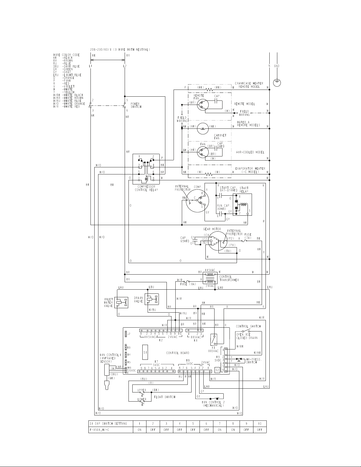
117
2. F-1501M_H(-C)
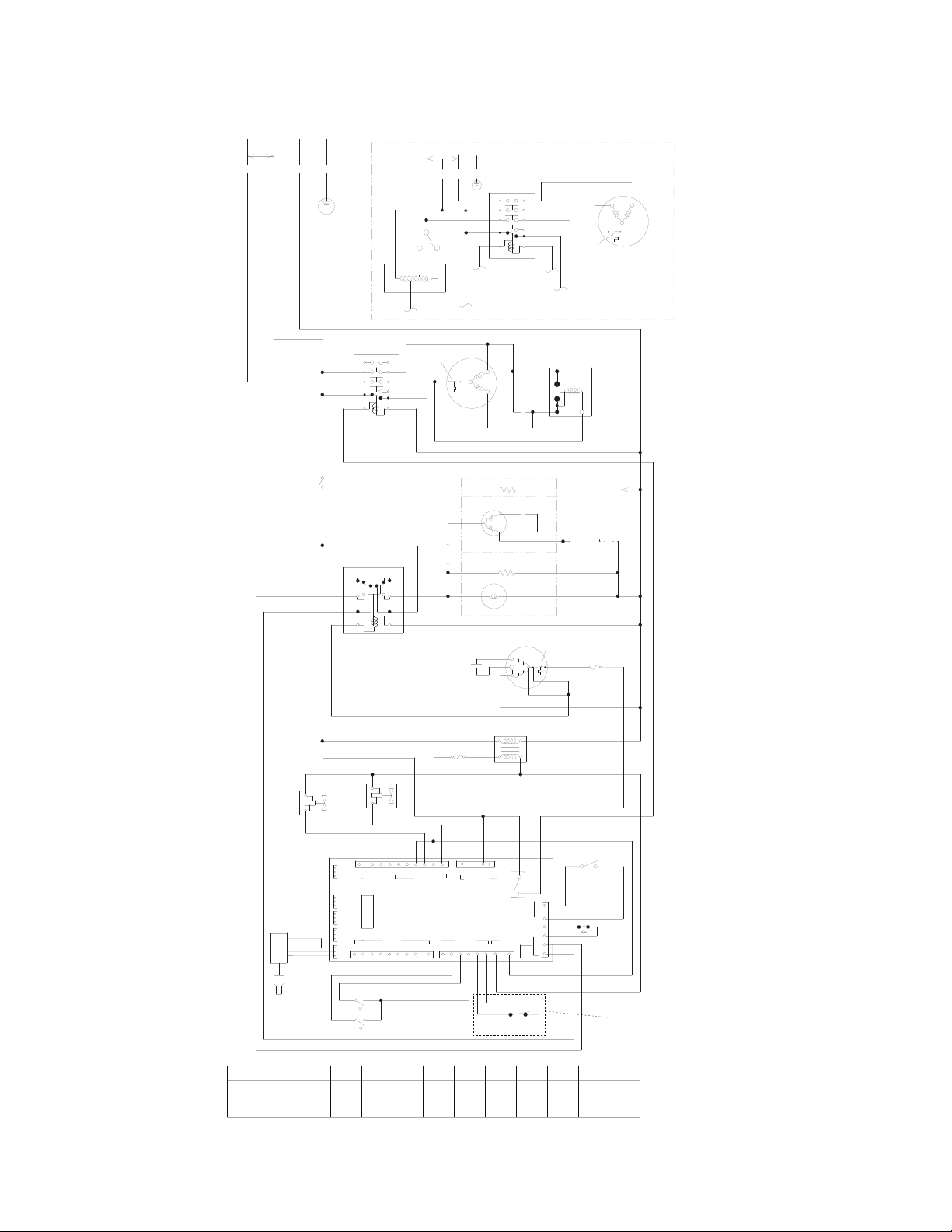
118
3. F-2001MWH(-C), F-2001MRH(-C)(3),F-2001MWJ, F-2001MRJ(-C)(3)
WIRE COLOR CODE
BK -BLACK
BR -BROWN
BU -BLUE
DBU -DARK BLUE
GR -GREEN
GY -GRAY
LBU -LIGHT BLUE
O -ORANGE
P -PINK
R -RED
V -VIOLET
W -WHITE
Y -YELLOW
W/BK -WHITE BLACK
W/BR -WHITE BROWN
W/BU -WHITE BLUE
W/O -WHITE ORANGE
W/R -WHITE RED
(T2)
(C2)
N
W/O
W/O
O
CAP.
65MFD
GND
S2
S1
X1
115VAC
K9
5VDC
K5
K4
K3
J2
(C1)
FUSE (1A)
FUSE
(7A)
L1
W/R
R
LBU
R
CONTROL
TRANSFORMER
Y
W/BK
W/BK
GY
FLOAT SWITCH
(BU)
(R)
(BK)
O
W/BU
INLET
WATER
VALVE
CONTROL SWITCH
DRAIN
VALVE
CONTROL BOARD
BR
W
BR
V
LBU
UPPER
LOWER
115VAC
24VAC
W/O
W/O
LBU
LBU
LBU
W/R
W/R
W/R
W/R
BR
BK
V
W
W
BR
LBU
OPEN:ICE
CLOSED:DRAIN
BU
R
BK
W/O
W/O
COMPRESSOR
CONTROL RELAY
1
3
5
7
2
4
6
8
POWER
SWITCH
GY
START CAP.
189-227MFD
RUN CAP.
40MFD
START
RELAY
1
2
5
COMP.
R
C
S
GY
R
R
R
O
BK
BK
BK
BK
BK
HI-PRESS.
SWITCH
CRANKCASE HEATER
REMOTE MODEL
Y
R
W/R
W/O
W/O
(BK)
(BK)
W
P
W
R
BR
BR
BR
(P1)
(P2)
(T1)
GY
GEAR MOTOR
BR
1
2
3
4
5
6
8 7 6 5 4 3 2 1
K7
5VDC
9 8 7 6 5 4 3 2 1
1 2 3
115VAC
K1
1 2 3 4 5 6 7 8 9 10
115VAC
K2
W
BK
LBU
W/R
BR
BR
BK
O
INTERNAL
PROTECTOR
INTERNAL
PROTECTOR
EVAPORATOR
HEATER
CUBLET MODEL
(W)
(W)
BIN CONTROL 2
(MECHANICAL)
GY
L2
BR
5
6
BR
BK
208-230/60/1 (1 PHASE - 3 WIRE WITH NEUTRAL FOR 115V)
O
W
W
W/BU
BR
BK
BR
V
W
BK
BK
GY
3
2
1
K6
20VDC
REMOTE MODEL
(BR)
(W)
WATER &
REMOTE MODELS
(BK)
(BK)
W
BK
W
W
FIELD
WIRING
W
W
W
BK
24VAC
K8
5VDC
CAP.
FAN
FAN
O
O
GY
MAGNETIC
CONTACTOR
L3
L2
L1
COM
T3
T2
T1
C1
C2
NO
NC
W
W
V
V
V
V
BK
R
BR
BR
BK
V
W
P
FIELD
WIRING
BR
W
W/O
W/O
BK
BK
R
BR
L2 L3L1
208-230/60/3 (3 PHASE)
GND
R
COMP.
INTERNAL
PROTECTOR
MAGNETIC
CONTACTOR
L3
L2
L1
COM
T3
T2
T1
C1
C2
NO
NC
R
BK
R
BR
BR
BK
R
W
P
R
BR
BR
VOLTAGE
TAP SW.
BK BK
MAIN
TRANSFORMER
0V
230V
208V
115V
P
W
W
(BR)
(W)
(DBU)
BIN CONTROL 1
(INFRARED
SENSOR)
(BK)
S1 DIP SWITCH SETTING 1 2 3 4 5 6 7 8 9 10
F-2001MWH/-C
F-2001MRH/-C(3)
F-2001MWJ/-C
F-2001MRJ/-C(3)
ON OFF OFF OFF OFF OFF ON ON OFF OFF
KD2
BR
W
BR
W
BK
BK
BR
BR
BR
R
BR
BK
R
W
W
W
LBU
O
V
W
24VAC
M_H(-C) Models Only
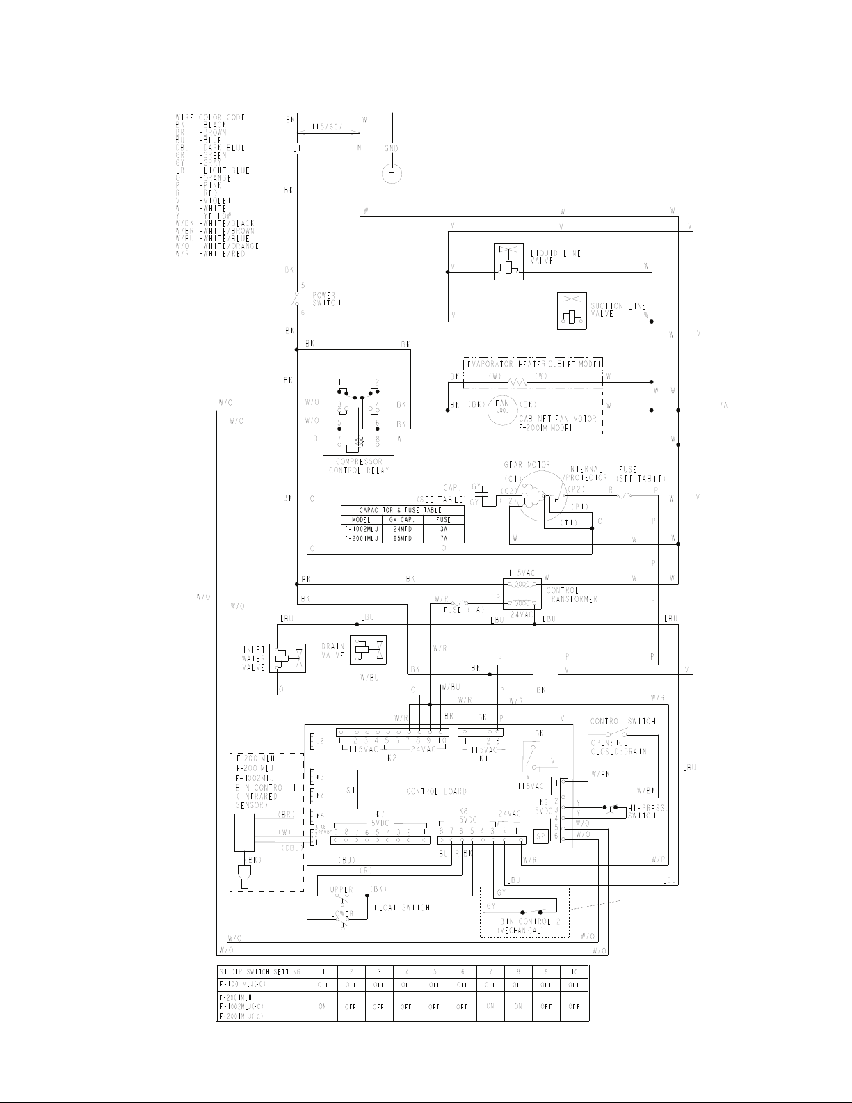
119
4. F-2001MLH, F-1001MLJ, F-1002MLJ, F-2001MLJ
F-1001MLJ and
F-2001MLH Only
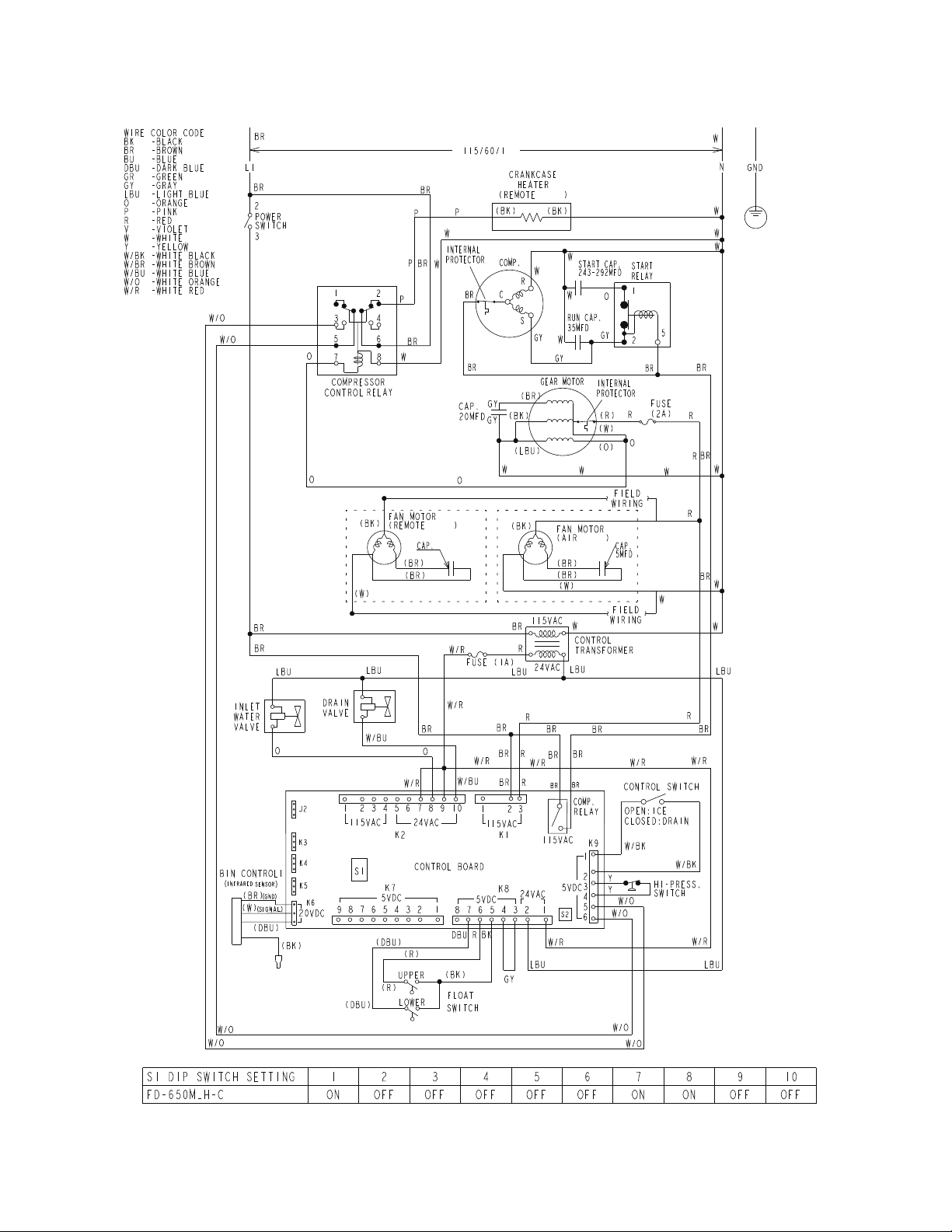
120
5. FD-650M_H-C
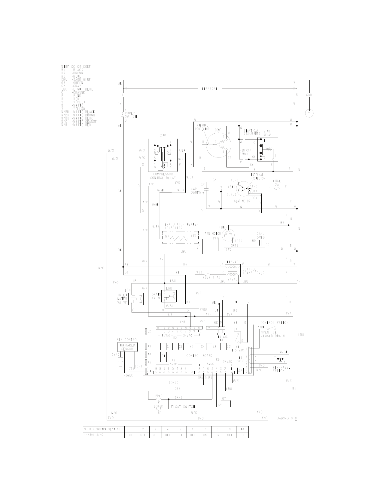
121
6. F-450MAJ(-C)
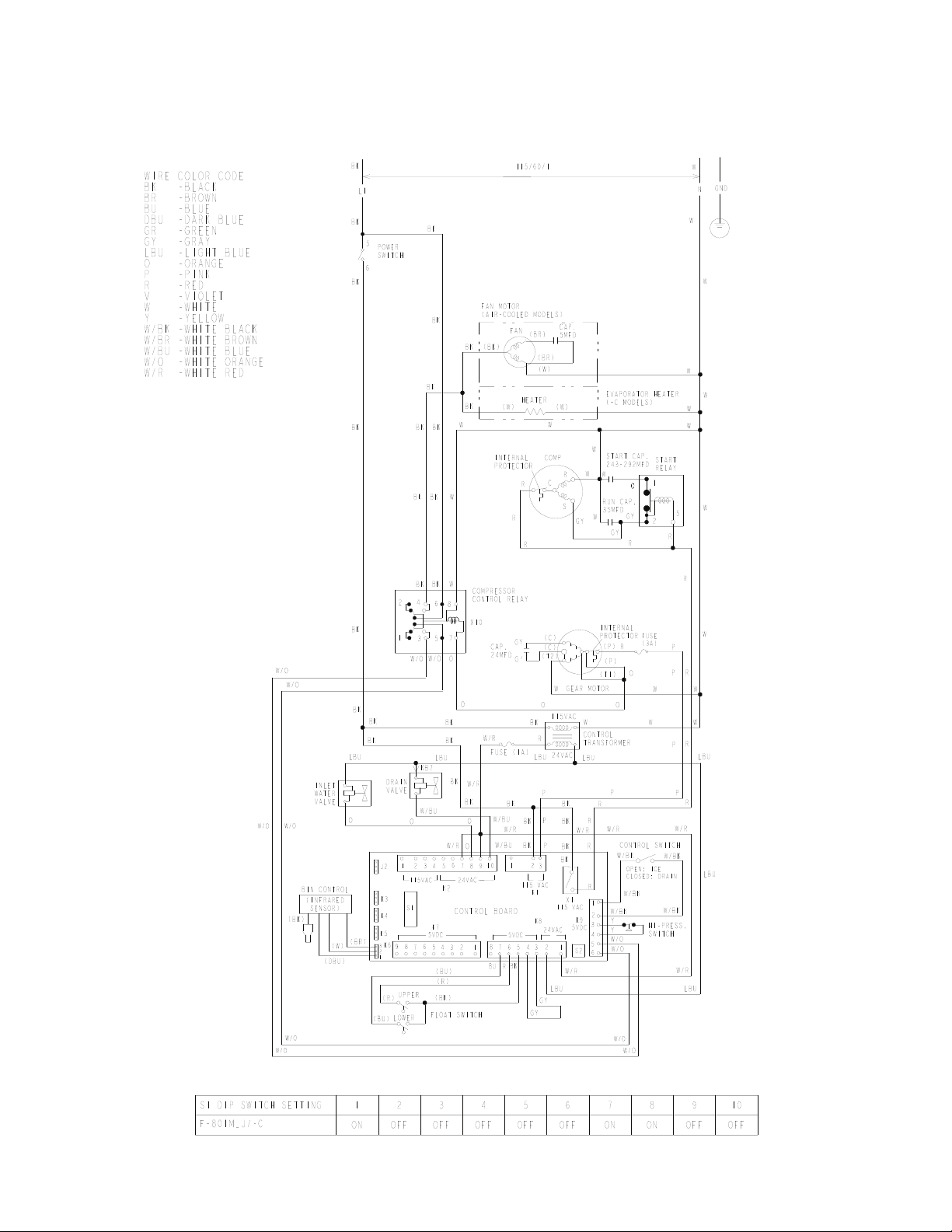
122
7. F-801M_J(-C)
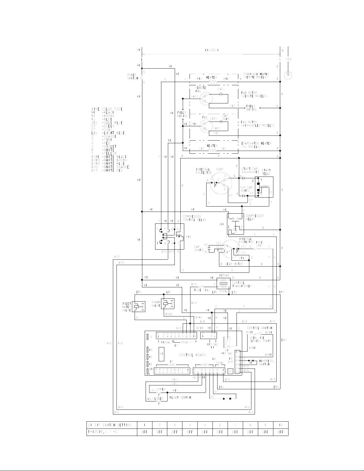
123
8. F-1001MAJ(-C), F-1001MWJ(-C), F-1001MRJ(-C)
BIN CONTROL 2
(MECHANICAL)
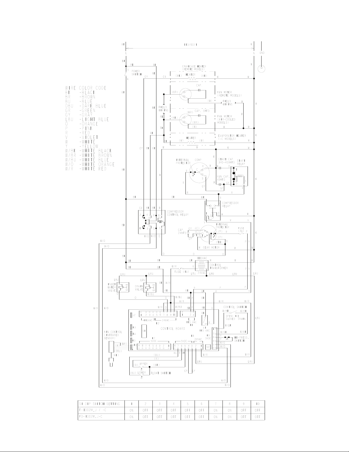
124
9. F-1002MAJ(-C), F-1002MWJ(-C), F-1002MRJ(-C), FD-1002M_J-C
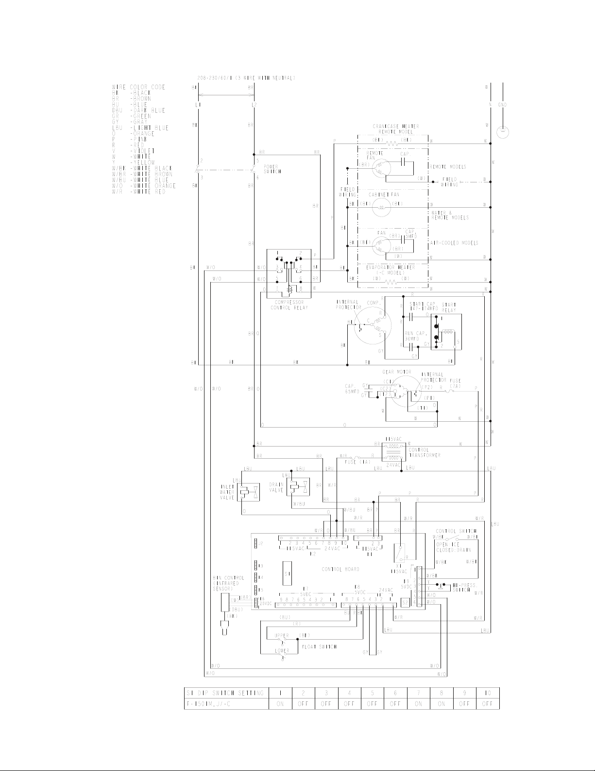
125
10. F-1501M_J(-C)
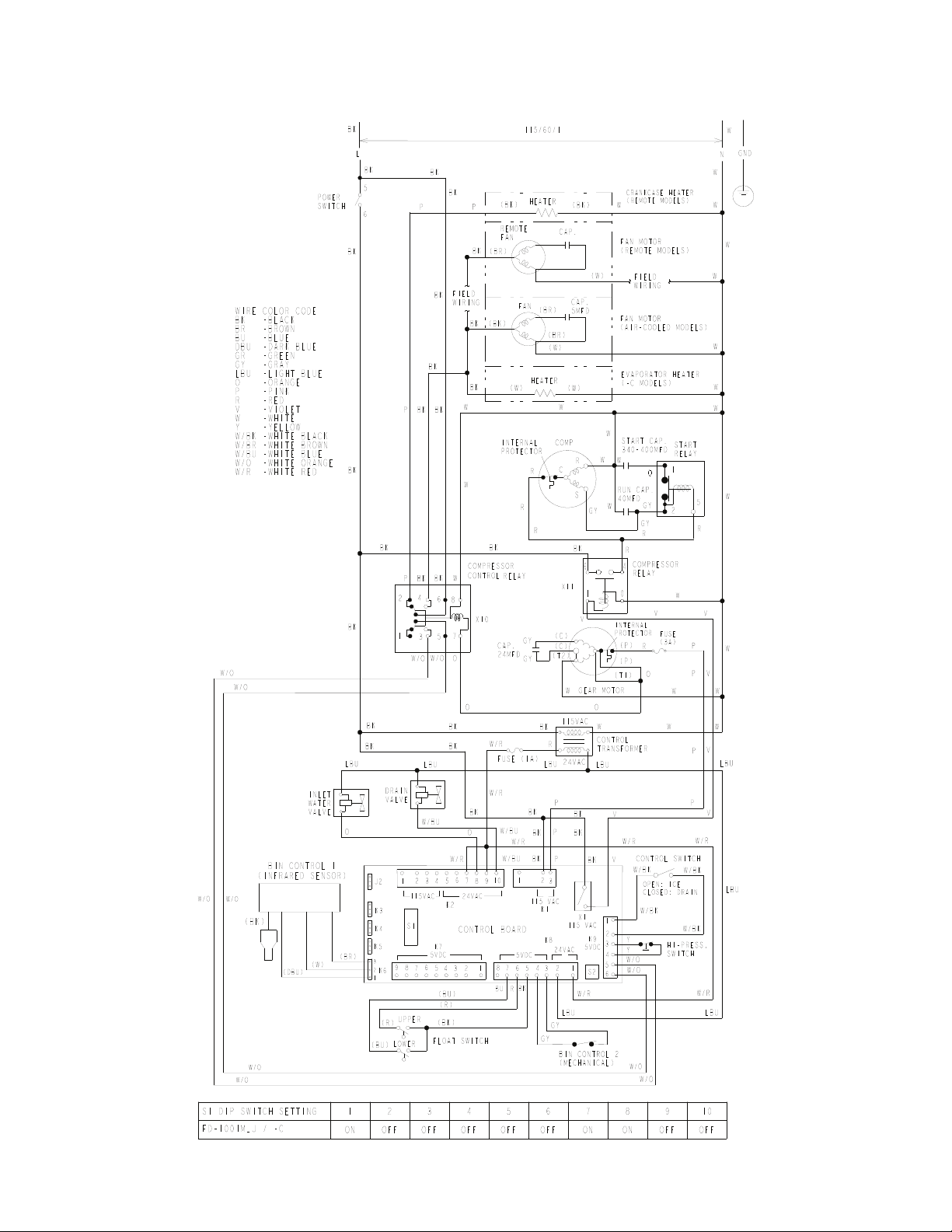
126
11. FD-1001M_J-C