
Loading ...
Loading ...
Loading ...
25
C. Control Board Check
Before replacing a control board that does not show a visible defect and that you suspect
is bad, always conduct the following check procedure. This procedure will help you verify
your diagnosis.
1) Check CB S1 dip switch settings to assure that they are in the factory default position.
For factory default settings, see "III.B.1. Default Dip Switch Settings."
Note: S1 dip switch 7determines bin control application:
BC (mechanical stand-alone) or BC2 (mechanical backup only): S1 dip switch 7 in
the "OFF" position.
BC1 (infrared sensor stand-alone) or with BC2 (mechanical backup): S1 dip switch
7in the "ON" position.
2) Move the power switch to the "ON" position and move the control switch to the "ICE"
position. The "POWER OK" LED turns on. Diagnosis "POWER OK" LED: Check that
the CB "POWER OK" LED is on. If not, check for proper supply voltage (115VAC) input
to the control transformer (power switch, breaker, and fuse). Next, check for proper
low-voltage (24VAC) output from the control transformer and that the 1A fuse is good.
Check for 24VAC at CB K8 #1 (W/R) to CB K8 #2 (LBU). If 24VAC is present and the
"POWER OK" LED is off, replace CB.
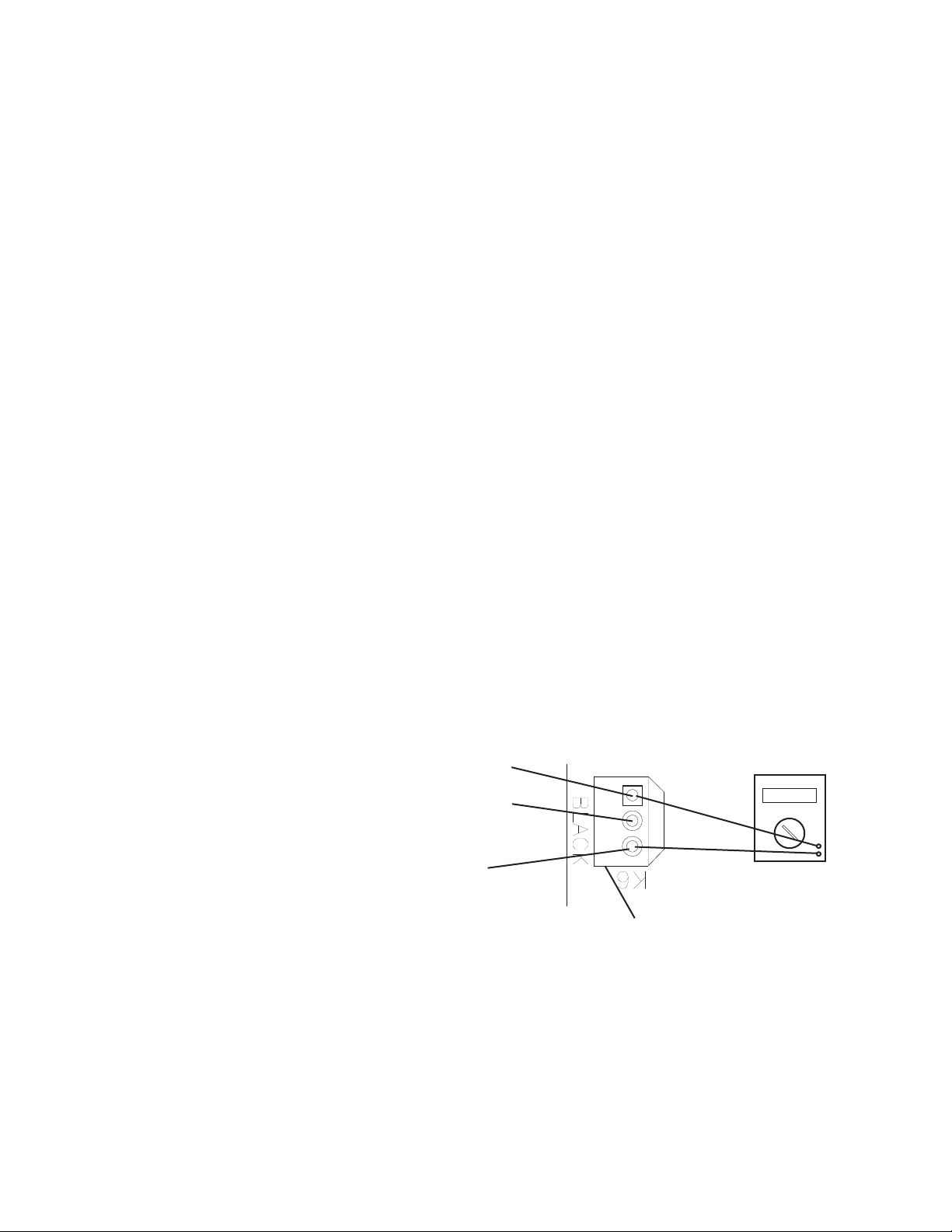
3) BC1 (infrared sensor) Power Supply (K6 connector): CB supplies 20VDC to BC1
and BC1 green LED is on. Diagnosis: Check that BC1 green LED is on. If not, check
for 20VDC between CB K6 #1 (DBU) and CB K6 #3(BR). See Fig. 1. If 20VDC is not
present, replace CB. If 20VDC is present, conrm that the yellow LED is not ashing
or steady. If BC1 yellow LED is on or ashing, move ice away from lens. If no ice is
present, clean the lens with a warm, clean damp cloth. If cleaning the lens does not
work, replace BC1 (infrared sensor).
Fig. 1
Red Positive
Test Lead
Black Negative
Test Lead
20VDC
Multimeter
3
2
1
K6 #3
Brown (BR)
K6 #2
White (W)
K6 #1
Dark Blue (DBU)
• K6 Connector
BC1 (Infrared Sensor)
BC1 (infrared sensor) (20VDC)
Open (yellow LED ashing or steady)
20VDC K6 #1 (DBU) to K6 #3 (BR)
0VDC K6 #1 (DBU) to K6 #2 (W)
20VDC K6 #2 (W) to K6 #3 (BR)
BC1 (infrared sensor) (20VDC) Closed
20VDC K6 #1 (DBU) to K6 #3 (BR)
20VDC K6 #1 (DBU) to K6 #2 (W)
0VDC K6 #2 (W) to K6 #3 (BR)
Loading ...
Loading ...
Loading ...