Loading ...
Loading ...
Loading ...
40
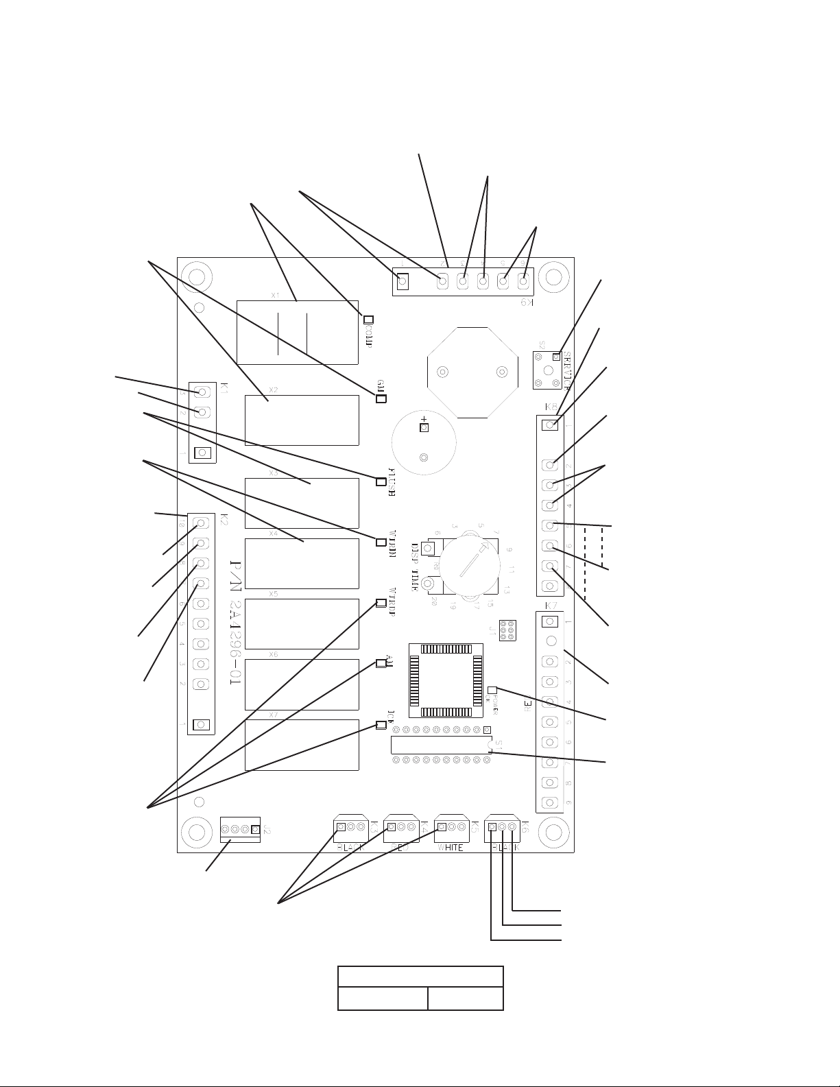
1. Control Board Layout
• K1 Connector
(115VAC)
GM, CCR/GMPR, EH,
FM, FMR #3
115VAC Input #2
Drain Valve #10
Control Transformer
24VAC Input
#1 (white/red)
Upper Float Switch
#6 (red) (5VDC)
Compressor Control Relay Circuit/Gear
Motor Protect Relay Circuit
#5 to #6 (white/orange) (5VDC)
High-Pressure Switch
#3 to #4 (yellow) (5VDC)
Control Switch
#1 to #2 (white/black) (5VDC)
• "POWER OK" LED
Control Transformer
24VAC Neutral
#2 (light blue)
Lower Float Switch
#7 (blue) (5VDC)
Float Switch
#5 (black) (5VDC)
• S1 Dip Switch
• K8 Connector
(24VAC and 5VDC)
• K7 Connector-Open
• K2 Connector
(24VAC)
5VDC common terminals
• K3 Connector-Open
• K4 Connector-Open
• K5 Connector-Open
Inlet Water
Valve #8
3 2 1
(DRAIN)
• K6 Connector (20VDC)
Bin Control 1 (infrared sensor)
(dark blue)
(white, signal (common))
(brown (ground))
• J2 Connector-Open
Water Dispensing
Valve, Agitation
Motor, and Ice
Dispensing LEDs
(not used on
these models)
Control Transformer
24VAC Input
#7 (white/red)
Control Transfor mer
24VAC Input
#9 (white/red)
• S2 "SERVICE" Button
(Ice Purge Cycle Bypass)
Bin Control (2) (mechanical)
#3 & #4 (gray) (5VDC)
• "FLUSH" LED
(X3 Relay) (drain)
DV
• "WTRIN" LED
(X4 Relay)
WV
• "GM" LED
(X2 Relay)
GM
• "COMP" LED
(X1 Relay)
Comp, LLV, SLV
• K9 Connector (5VDC)
Control Board
Part Number
2A8054-01
Loading ...
Loading ...
Loading ...