Loading ...
Loading ...
Loading ...
30
D. Bin Control Check
1. Bin Control 1 (infrared sensor) Check
IMPORTANT
Make sure CB S1 dip switch 7 is in the "ON" position. This allows the control board
to monitor BC1 (infrared sensor) along with BC2 (mechanical) backup bin control.
1) Turn off the power supply.
2) Remove the front panel, top panel, and control box cover.
3) Conrm that CB S1 dip switch 1, 2, 3 are in the proper position for your application.
See "III.B.2. BC1 (Infrared Sensor) Shutdown Delay (S1 dip switch 1, 2, 3)."
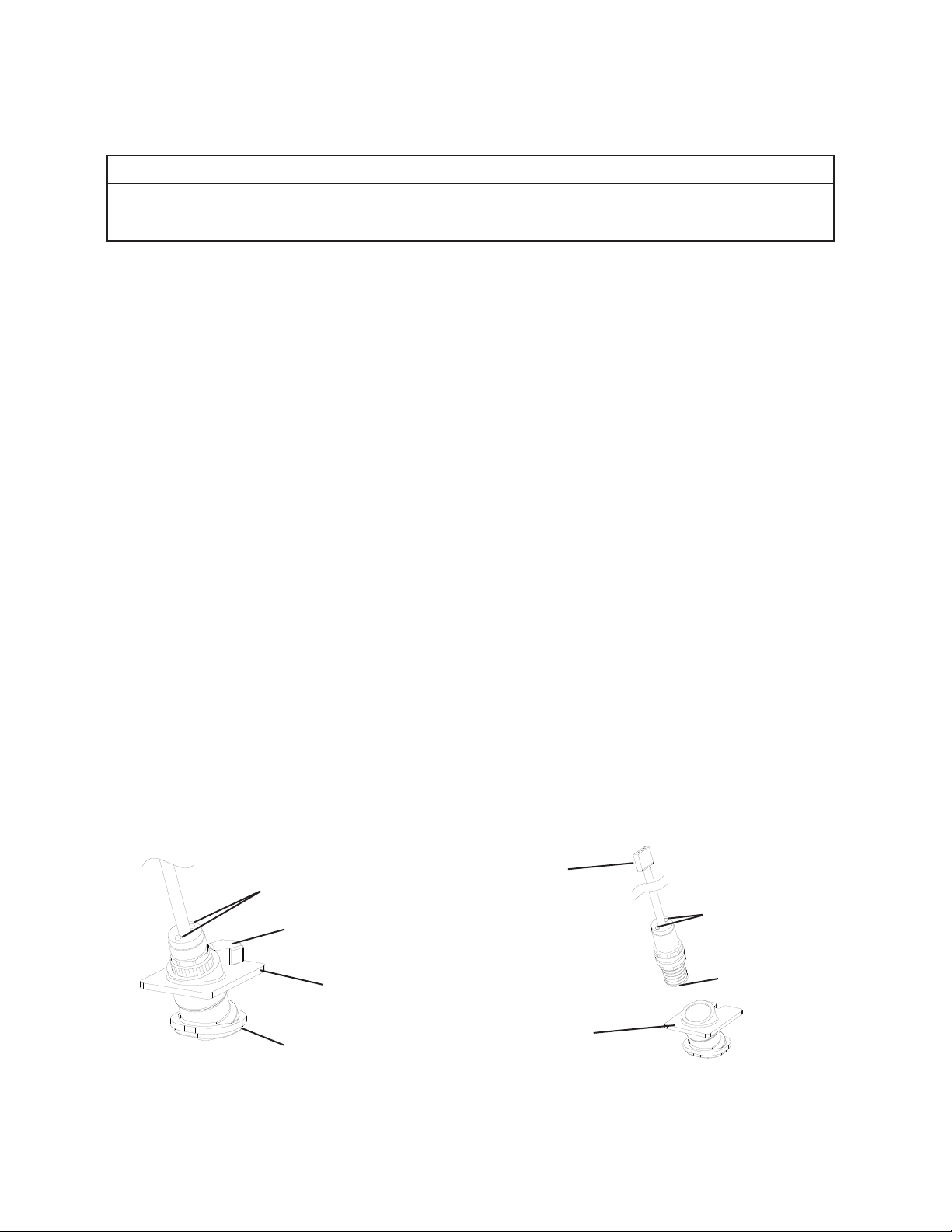
4) Conrm that BC1 is connected to CB K6 connector. Wipe down BC1 lens with a warm,
clean, damp cloth. If the bottom of the icemaker is not accessible in your application,
remove the thumbscrew securing the BC1 housing, then remove the housing from the
base. See Fig. 4.
5) Move the control switch to the "ICE" position, then move the power switch to the "ON"
position.
6) Turn on the power supply to start the automatic icemaking process. Check that BC1
green LED is on. The BC1 green LED conrms 20VDC power from CB to BC1 and
remains on constantly. Diagnosis: If the BC1 green LED is not on, conrm 20VDC
at CB K6 #1 (DBU) to CB K6 #3 (BR). If 20VDC is present and the BC1 green LED is
off, replace BC1. If not, see step "3) BC1 (infrared sensor) Power Supply," under "II.C.
Control Board Check.
7) Make sure CB "GM" LED is on. There is a delay of at least 30 sec. before the "GM" LED
turns on after power-up. After CB "GM" LED turns on, press CB "SERVICE" button to
bypass the 5-min. ice purge cycle. WARNING! Risk of electric shock. Care should be
taken not to touch live terminals.
Fig. 4
Housing
Connector
(20VDC from
K6 connector on
control board)
LEDs
Lens
Housing
Lens
LEDs
BC1 (infrared sensor)
Thumbscrew
Loading ...
Loading ...
Loading ...