Loading ...
Loading ...
Loading ...
6
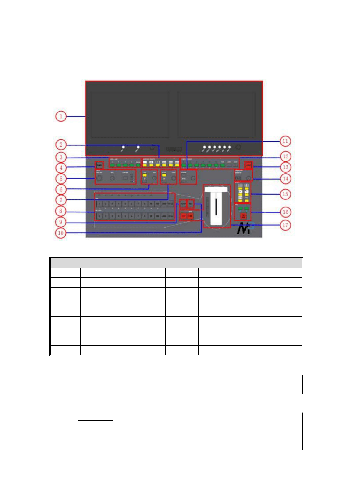
1.2.2 Front Panel
Panel Instruction
1
LCD display
10
AUX button
2
Multiview presets area
11
Menu area
3
Layer/Aux area
12
Stored presets area
4
Power button
13
Locking button
5
Position, Size and Control area
14
Transition time control area
6
DSK edit area
15
WIPE operation area
7
BLEND edit area
16
OSD edit area
8
Input sources area
17
Switch Modes area
9
Black button
Power Button
4
POWER:
Red light indicates standby, while yellow light indicates operating environment.
LCD Display
1
LCD Display
8 inch full-color display.
PVW Monitor (left): Multiview preview.
Loading ...
Loading ...
Loading ...