
USER MANUAL
Article No: RGB-RD-UM-M3 E001
Revision No: V1.1
M3
USER MANUAL

CONTENTS
CONTENTS
........................................................................................................................................................ 1
Declarations
..................................................................................................................................................... 1
FCC/Warranty
...........................................................................................................................................1
Operators Safety Summary
......................................................................................................................2
Installation Safety Summary
....................................................................................................................2
Chapter 1 Your Product
.................................................................................................................................... 1
1.1 In the Box
........................................................................................................................................... 1
1.2 Product Overview
.............................................................................................................................. 2
1.2.1 Back Panel
...............................................................................................................................3
1.2.2 Front Panel
..............................................................................................................................6
1.2.3 Dimension
.............................................................................................................................12
Chapter 2 Installing Your Product
.................................................................................................................. 13
2.1 Plugging in Signals
............................................................................................................................13
2.2 Plugging in Main Power
...................................................................................................................13
2.3 Turning on Your Product
..................................................................................................................13
Chapter 3 Using Your Product
........................................................................................................................14
3.1 Using the MENU Button
...................................................................................................................14
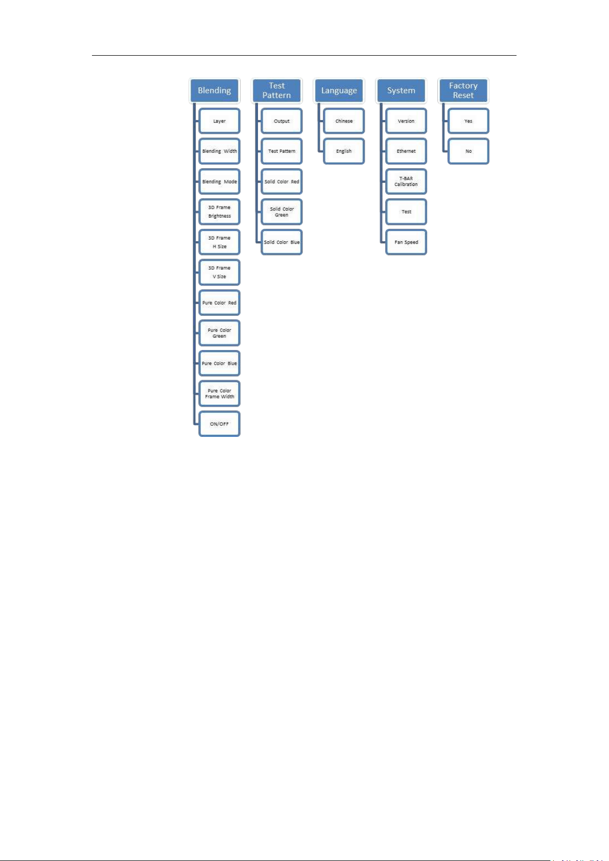
3.2 Understanding the MENU Structure
............................................................................................... 15
3.3 Using the Menu
................................................................................................................................17
3.3.1 Understanding the Main Menu
............................................................................................17
3.3.2 Input Menu
........................................................................................................................... 18
3.3.3 Output Menu
........................................................................................................................ 19
3.3.4 Background Menu
................................................................................................................ 20
3.3.5 MASK Menu
.......................................................................................................................... 21
3.3.6 DSK Menu
............................................................................................................................. 22
3.3.7 Blending Menu
......................................................................................................................23
3.3.8 Test Pattern
.......................................................................................................................... 24
3.3.8 Language Menu
.................................................................................................................... 24
3.3.9 System Menu
........................................................................................................................ 25
3.3.10 Factory Reset Menu
............................................................................................................26
3.4 PVW
..................................................................................................................................................27
3.5 PST
....................................................................................................................................................27
3.5.1 Signal Selection
.....................................................................................................................27
3.5.2 Add or Delete Layer
.............................................................................................................. 27
3.5.3 Freeze the Layer
....................................................................................................................27
3.5.4 Multiview Presets
................................................................................................................. 27
3.5.5 Set the Position
.....................................................................................................................28
3.5.6 Scale and Crop
...................................................................................................................... 28
3.5.7 DSK Settings
.......................................................................................................................... 29
3.5.8 BLEND Settings
......................................................................................................................30
3.5.9 WIPE Settings
........................................................................................................................34
3.5.10 Mask Settings
......................................................................................................................34

3.5.11 Custom OSD
........................................................................................................................ 35
3.5.12 Custom MASK
..................................................................................................................... 36
3.5.13 Custom LOGO
......................................................................................................................35
3.5.14 Custom STILL
.......................................................................................................................37
3.6 PGM Mode
.......................................................................................................................................38
3.7 AUX Mode
........................................................................................................................................ 39
3.7.1 AUX Splicing
.......................................................................................................................... 39
3.7.2 AUX&LOOP Splicing
.............................................................................................................. 42
3.7.3 PGM&AUX Splicing
............................................................................................................... 46
3.8 4K1K Mode
.......................................................................................................................................50
3.9 Switch Image
....................................................................................................................................51
3.10 Set the Output Resolution
.............................................................................................................51
3.10.1 Select the Output Resolution
............................................................................................. 51
3.10.2 Custom Output Resolution
.................................................................................................51
3.11 Using Black Out
..............................................................................................................................52
3.12 Saving Views
...................................................................................................................................53
3.13 Recall Saved Settings
......................................................................................................................54
Chapter 4 Ordering Codes
..............................................................................................................................55
4.1 Product
.............................................................................................................................................55
4.2 Options
.............................................................................................................................................55
4.2.1 Input Options
........................................................................................................................55
4.2.2 Output Options
.....................................................................................................................55
Chapter 5 Support
........................................................................................................................................56
5.1 Questions and Troubleshooting
.......................................................................................................56
5.1.1 Customize the MASK, LOGO and STILL
.................................................................................56
5.1.2 Add the Layer
........................................................................................................................56
5.1.3 Input and Output Option Module Type
............................................................................... 56
5.1.4 Blending and MASK cannot open synchronously
.................................................................56
5.2 Contact Us
........................................................................................................................................57
Chapter 6 Appendix
........................................................................................................................................58
6.1 Specification
.....................................................................................................................................58
6.2 Software Upgrade
............................................................................................................................ 63
6.3 Module Installation
........................................................................................................................70
6.4 Terms & Definitions
......................................................................................................................... 74
6.5 Revision History
............................................................................................................................... 78

Thank you for choosing our product!
This User Manual is designed to show you how to use this video processor quickly and make use of all
the features. Please read all directions and instructions carefully before using this product.
Declarations
FCC/Warranty
Federal Communications Commission (FCC) Statement
This equipment has been tested and found to comply with the limits for a class A digital device, pursuant
to Part 15 of the FCC rules. These limits are designed to provide reasonable protection against harmful
interference when the equipment is operated in a commercial environment. This equipment generates,
uses, and can radiate radio frequency energy and, if not installed and used in accordance with the
instruction manual, may cause harmful interference to radio communications. Operation of this
equipment in a residential area may cause harmful interference, in which case the user will be
responsible for correcting any interference.
Guarantee and Compensation
RGBlink provides a guarantee relating to perfect manufacturing as part of the legally stipulated
terms of guarantee. On receipt, the purchaser must immediately inspect all delivered goods for
damage incurred during transport, as well as for material and manufacturing faults. RGBlink must be
informed immediately in writing of any complains.
The period of guarantee begins on the date of transfer of risks, in the case of special systems and
software on the date of commissioning, at latest 30 days after the transfer of risks. In the event of
justified notice of compliant, RGBlink can repair the fault or provide a replacement at its own discretion
within an appropriate period. If this measure proves to be impossible or unsuccessful, the purchaser can
demand a reduction in the purchase price or cancellation of the contract. All other claims, in particular
those relating to compensation for direct or indirect damage, and also damage attributed to the
operation of software as well as to other service provided by RGBlink, being a component of the system
or independent service, will be deemed invalid provided the damage is not proven to be attributed to
the absence of properties guaranteed in writing or due to the intent or gross negligence or part of
RGBlink.
If the purchaser or a third party carries out modifications or repairs on goods delivered by RGBlink, or if
the goods are handled incorrectly, in particular if the systems are commissioned operated incorrectly or if,
after the transfer of risks, the goods are subject to influences not agreed upon in the contract, all
guarantee claims of the purchaser will be rendered invalid. Not included in the guarantee coverage are
system failures which are attributed to programs or special electronic circuitry provided by the purchaser,
e.g. interfaces. Normal wear as well as normal maintenance are not subject to the guarantee provided by
RGBlink either.
The environmental conditions as well as the servicing and maintenance regulations specified in this
manual must be followed by the customer.

Operators Safety Summary
The general safety information in this summary is for operating personnel.
Do Not Remove Covers or Panels
There are no user-serviceable parts within the unit. Removal of the top cover will expose dangerous
voltages. To avoid personal injury, do not remove the top cover. Do not operate the unit without the
cover installed.
Power Source
This product is intended to operate from a power source that will not apply more than 230 volts rms
between the supply conductors or between both supply conductor and ground. A protective ground
connection by way of grounding conductor in the power cord is essential for safe operation.
Grounding the Product
This product is grounded through the grounding conductor of the power cord. To avoid electrical shock,
plug the power cord into a properly wired receptacle before connecting to the product input or output
terminals. A protective-ground connection by way of the grounding conductor in the power cord is
essential for safe operation.
Use the Proper Power Cord
Use only the power cord and connector specified for your product. Use only a power cord that is in good
condition. Refer cord and connector changes to qualified service personnel.
Use the Proper Fuse
To avoid fire hazard, use only the fuse having identical type, voltage rating, and current rating
characteristics. Refer fuse replacement to qualified service personnel.
Do Not Operate in Explosive Atmospheres
To avoid explosion, do not operate this product in an explosive atmosphere.
Installation Safety Summary
Safety Precautions
For all M3 processor installation procedures, please observe the following important safety and handling
rules to avoid damage to yourself and the equipment.
To protect users from electric shock, ensure that the chassis connects to earth via the ground wire
provided in the AC power Cord.
The AC Socket-outlet should be installed near the equipment and be easily accessible.
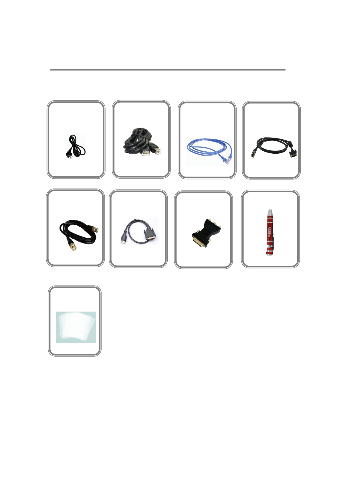
Unpacking and Inspection
Before opening M3 processor shipping box, inspect it for damage. If you find any damage, notify the

shipping carrier immediately for all claims adjustments. As you open the box, compare its contents
against the packing slip. If you find any shortages, contact your sales representative.
Once you have removed all the components from their packaging and checked that all the listed
components are present, visually inspect the system to ensure there was no damage during shipping. If
there is damage, notify the shipping carrier immediately for all claims adjustments.
Site Preparation
The environment in which you install your M3 should be clean, properly lit, free from static, and have
adequate power, ventilation, and space for all components.

2
1.2 Product Overview
M3 brings together sophisticated presentation switching with advanced mixing capabilities into a
single device. The vision mixer console includes broadcast style features for quick access during
any performance, along with dual eight-inch LCD displays to monitor video sources, full preview,
as well as live/program display monitoring. At the rear of the M3, the familiar X3 modular routing
platform become apparent, with a host of new options and features tailored to presentation
applications.
Entirely module, right down to fans, filters, and PSU, M3 is fitted as standard with modules for
preview and monitoring, communications and Genlock sync. From there, there is an impressive
choice of both inputs and output options.
The on board displays can be configured to show outputs as physically arranged, or in any way.
Large tactical illuminated buttons along with T-Bar mixing control. Powerful, yet compact, M3 is a
fully integrated scaling, processing and mixing for processing and mixing for professional
environments from entertainment to integration.
3
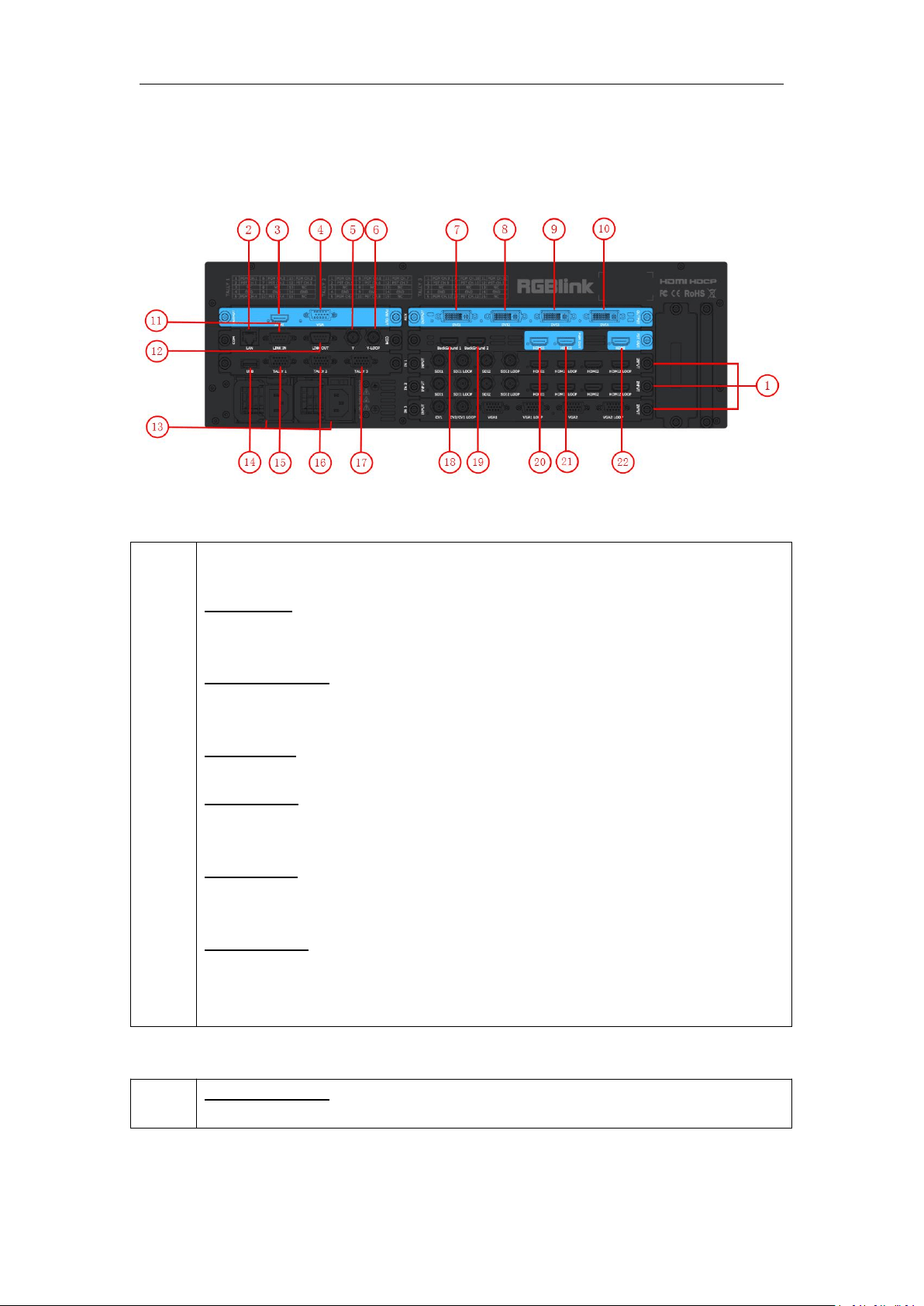
1.2.1 Back Panel
Input Option Slots
1
M3 provides 3 optional input slots. A range of inputs are available for user fitting,
including DVI, VGA, HDMI, USB, CVBS and SDI.
DVI-I – DVI
Each DVI module supports 4 DVI-I inputs. Standard DVI signals can input. The DVI
port supports up to HDMI 1.3 if the port format is set to HDMI.
HDMI-A – HDMI
Each HDMI module supports 4 HDMI-A inputs. Standard signal from computer can
input.
DB15 – VGA
Each VGA module supports 4 DB15 inputs. Standard VGA signals can input.
BNC – CVBS
Each CVBS module supports 8 BNC inputs. Standard video signal from players,
cameras can input.
USB-A– USB
Each USB module supports 4 USB-A inputs. Access the USB device or mobile hard
disk with USB storage function. Support general image and video formats.
BNC – 3G-SDI
Each SDI module supports 4 SDI inputs and 4 SDI loop outputs. Standard 3G-SDI
signals can input. SDI loop input can be connected to another M3 or device with SDI
input.
Background Input
18. 19
HDMI-A – HDMI
Standard signal from computer can input.
4
AUX Output
7. 8. 9.
10
DVI-I – DVI (Choose from DVI/SDI/HDMI )
Connect to the monitor or LED display which has DVI interface. (This connector does
not support hotplug).
PGM Output
20. 21
HDMI-A – HDMI
Connect to the display device, video processor or matrix.
PST Output
22
HDMI-A – HDMI
Connect to the display device, video processor or matrix.
PVW Output
3
HDMI-A – HDMI
Connect to the display device, video processor or matrix.
4
DB15 – VGA
Connect to the monitor or LED display which has VGA interface. (This connector does
not support hotplug).
Control Connectors
2
RJ45 – Ethernet
Connect to Ethernet work for remote control by Windows control software.
14
USB-B – USB
For customizing LOGO, OSD, STILL and MASK saving, and can be loaded. Plus
Upgrading.
11. 12
RS-232
Used for cascade and firmware upgrade.
11: LINK IN is serial female port, the serial communication interface of RS-232 control
protocol and multiple cascading control.
12: LINK OUT is serial male port, the serial communication interface of multiple
devices
cascading control, connect devices through DB9 serial cable.
5. 6
BNC-Genlock
5: Genlock input, standard Genlock signal can input.
6: Genlock loop output, can connect to the Genlock input of the next M3 or the device
with Genlock input.
15. 16.
17
TALLY Light

5
Power Connection
13
IEC – Power Input
Main power input AC 100-240V Max 205W.
6
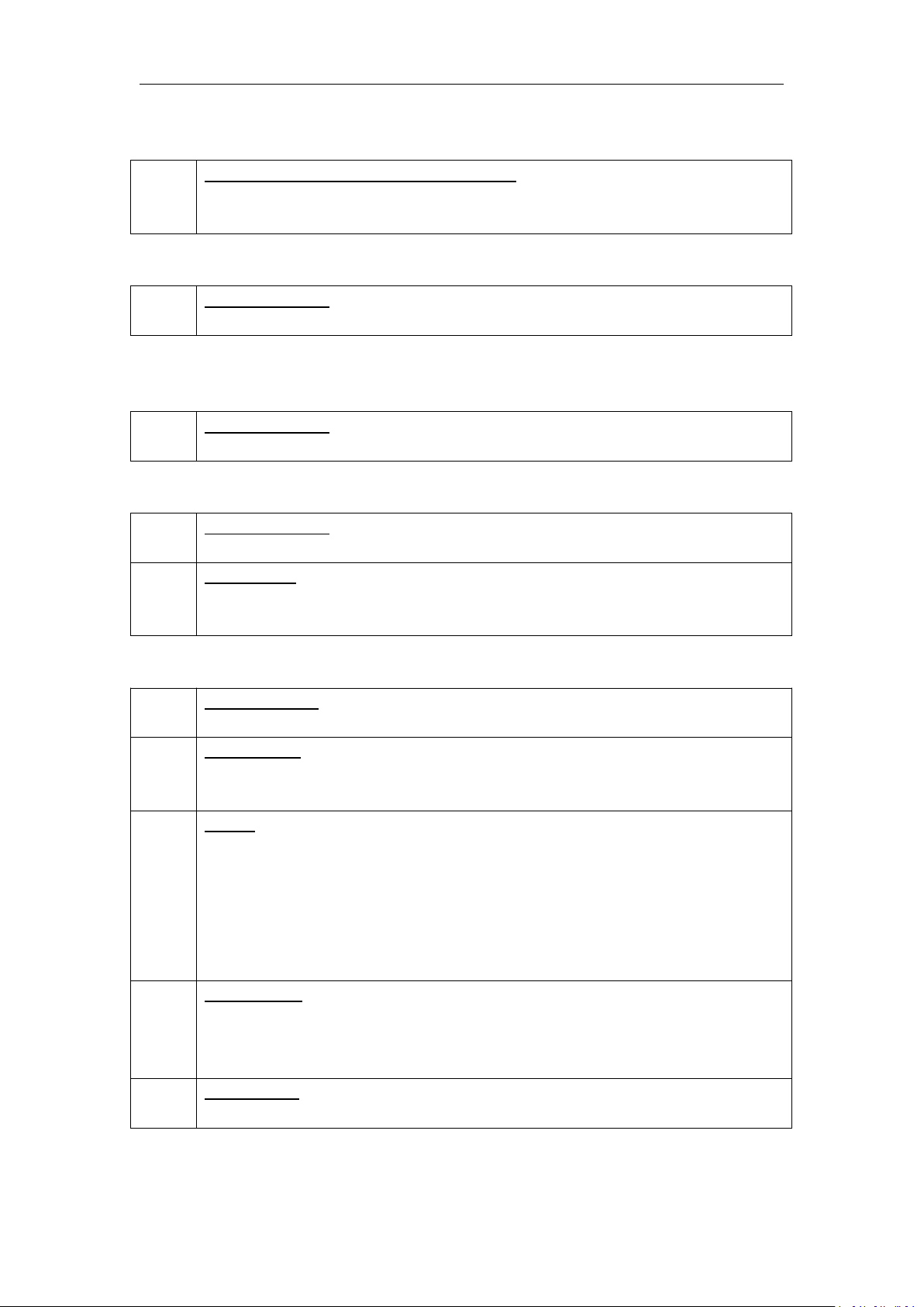
1.2.2 Front Panel
Panel Instruction
1
LCD display
10
AUX button
2
Multiview presets area
11
Menu area
3
Layer/Aux area
12
Stored presets area
4
Power button
13
Locking button
5
Position, Size and Control area
14
Transition time control area
6
DSK edit area
15
WIPE operation area
7
BLEND edit area
16
OSD edit area
8
Input sources area
17
Switch Modes area
9
Black button
Power Button
4
POWER:
Red light indicates standby, while yellow light indicates operating environment.
LCD Display
1
LCD Display
8 inch full-color display.
PVW Monitor (left): Multiview preview.
7
PVW
Eight images and single image preview switching button.
CHNL
Customize source channels (8 out of 12).
Rotary
For PVW menu selections, adjustment and confirmation.
PST/PGM Monitor (right): Preview edit.
PGM
For PST and PGM switching.
LOGO
Customize the logo.
OSD
Customize the OSD.
STILL
Customize the STILL.
AUX
Quick split for PGM/AUX output card.
FMT
Output format settings button.
Rotary Knob
For PST menu selections, adjustment and confirmation.
Layer/Aux Button
3
Button 1/2/3/4
For adding or deleting the layer. The light is on when adding a layer, off when deleting a
layer and flickers when a layer is selected.
FREEZE
Freeze the image or video.
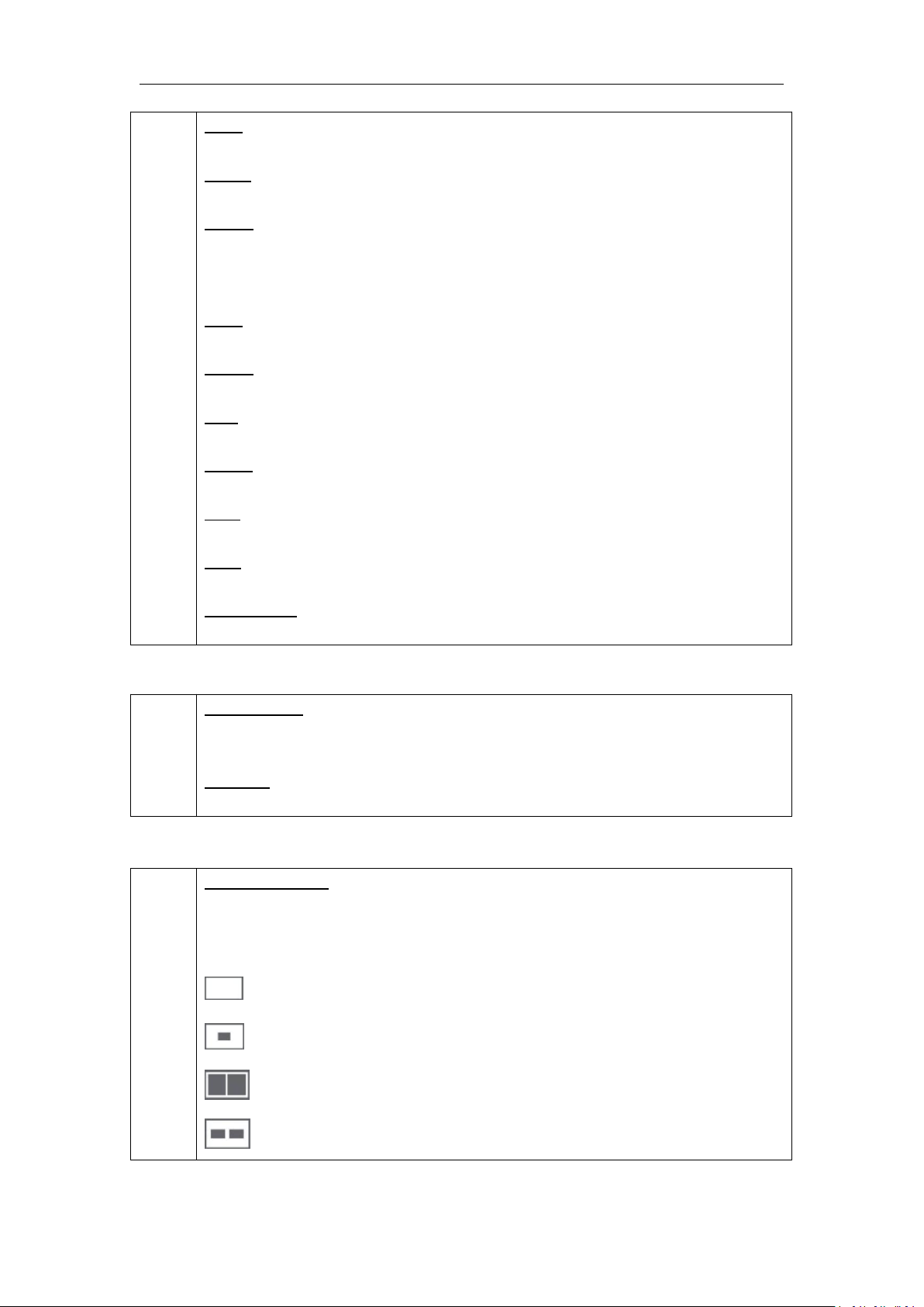
Multiview Presets Area
2
Multiview Presets
Multiview shortcut buttons.
The button light is on when a PIP mode is selected, mainly for layout settings quickly in
multiview.
: 1P
: PIP CENT
: SIDE BY SIDE
: 3P
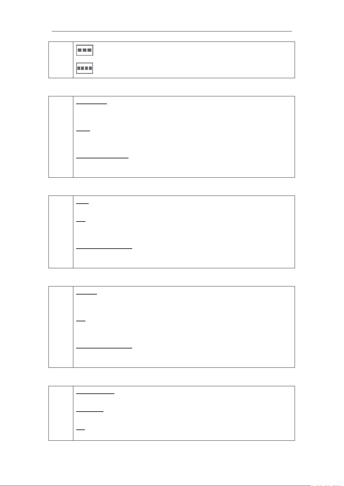
8
: 4P
: 5P
Position, Size and Control Area
5
CONTROL
Layer selection button. The light is on when a layer is added, flickers when the layer is
can be edited, off when there’s no layer.
SIZE
Size adjustment and crop settings.
For details, please refer to Scale and Crop.
POSITION Joystick
Position adjustment button.
For details, please refer to Set the Position.
DSK Edit Area
6
DSK
DSK effect editing button. User can select the layer and set the position in DSK menus.
ON
ON/OFF button. The button shines when selecting “ON”, and enable the DSK function.
Light is off when DSK function is turned off.
LEVEL Rotary Knob
Adjust the alpha of DSK layer.
For details, please refer to DSK Settings.
BLEND Edit Area
7
BLEND
BLEND effect editing button. User can select the layer and set the blending width in
BLEND menus.
ON
ON/OFF button. The button shines when selecting “ON”, and enables BLEND function.
Light is off when the BLEND function is turned off.
LEVEL Rotary Knob
Adjust the blend width.
For details, please refer to BLEND Settings.
Input Sources Area
8
LED Indicator
The button 1/2/3/4/5/6/7/8 is on when the signal or background input is selected for use.
PGM area
For indicating. User cannot change the channel or set the size or position in PGM area.
BK
For indicating. The button is on when enabling background function.
9
OSD
For indicating. The button is on when enabling OSD function.
LOGO
For indicating. The button is on when enabling LOGO function.
STILL
For indicating, the button is on when enabling STILL function.
1/2/3/4/5/6/7/8
When number input is needed, all the buttons representing number shine. It can be used
as direct number input of resolution and size.
PST/Aux area
For indicating, the button shines when output the signal in PST channel.
For selecting, Press any button to switch the PST signal.
For editing, (button light is on -- the channel is used but cannot be edited, button light is
flashing -- the channel can be edited, button light is off -- the channel is not selected.
BK
Editing function. The button shines when enabling background function.
OSD
Editing function. The button shines when enabling OSD function.
LOGO
Editing function. The button shines when enabling LOGO function.
STILL
Editing function. The button shines when enabling STILL function.
BLACK Button
9
BLACK
The button shines when enabling black function. Black is only available for PGM
channel.
AUX Button
10
AUX
AUX output settings, it can be customized.
Menu Area
11
SYSTEM
Menu or exit button.
For details, please refer to Understanding the MENU Structure.
ENTER
Confirmation button.
Menu Rotary Knob
Menu selection and confirmation button.
Stored Presets Area
12
SAVE
Support 36 saving modes.
10
LOAD
Load saved views 1 to 36.
PAGE
For save or load. 6 pages and 6 banks in total.
1/2/3/4/5/6 Button
The button shines when select PAGE or BANK.
Lock Top Panel Area
13
LOCK
Locking button. The button shines when the buttons in top panel are locked. Press the
button again, the button light is off and locking is null.
Transition Time Control Area
14
Double Digital Display Tube
Display the transition time.
Time Rotary Knob
Adjust transition time. The adjustment range is between 0.1S~5S.
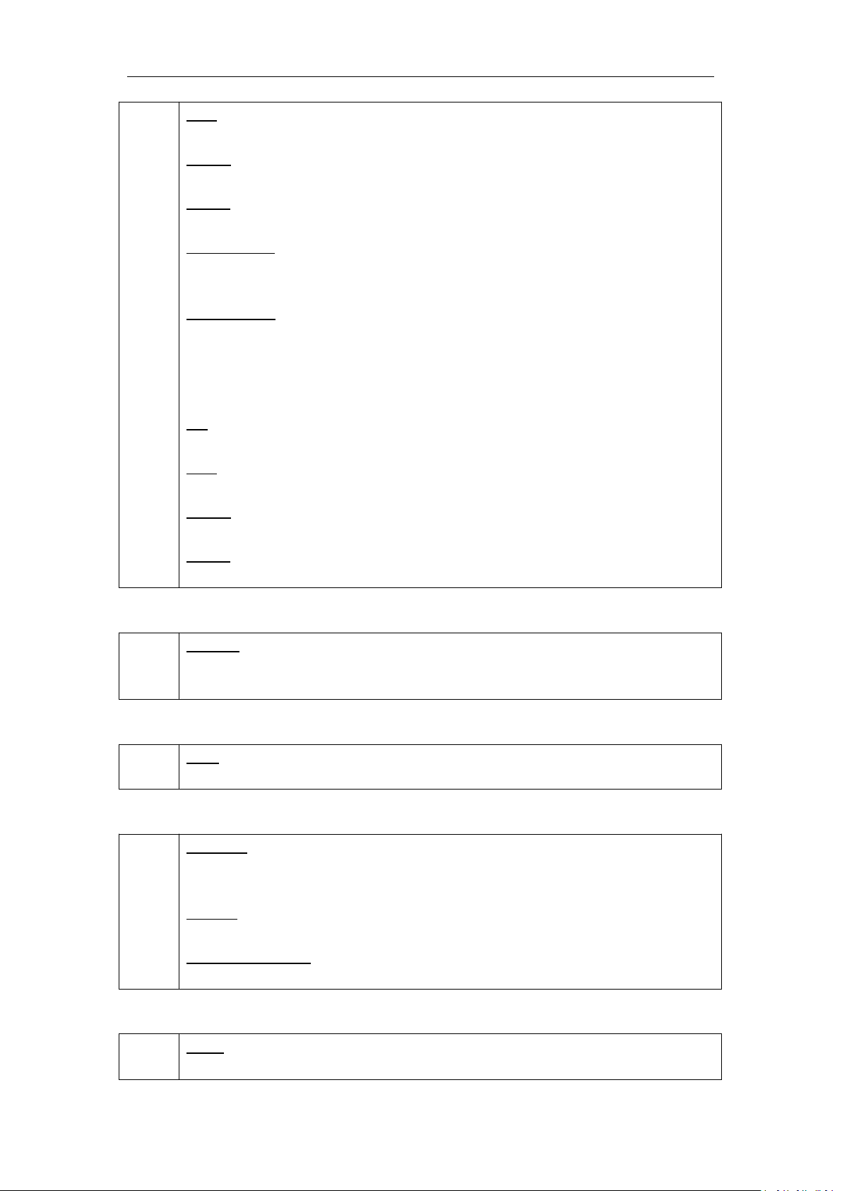
WIPE Operation Area
15
: Iris box ←□→, →□←, ←+→, →+←, L←M→R, T←M→B
: Iris round ←O→
: WIPE right/left R→L, L→R
: Push to bottom right T→B, B→T, TL→BR
: Blinds vertical ||||→
: FADE
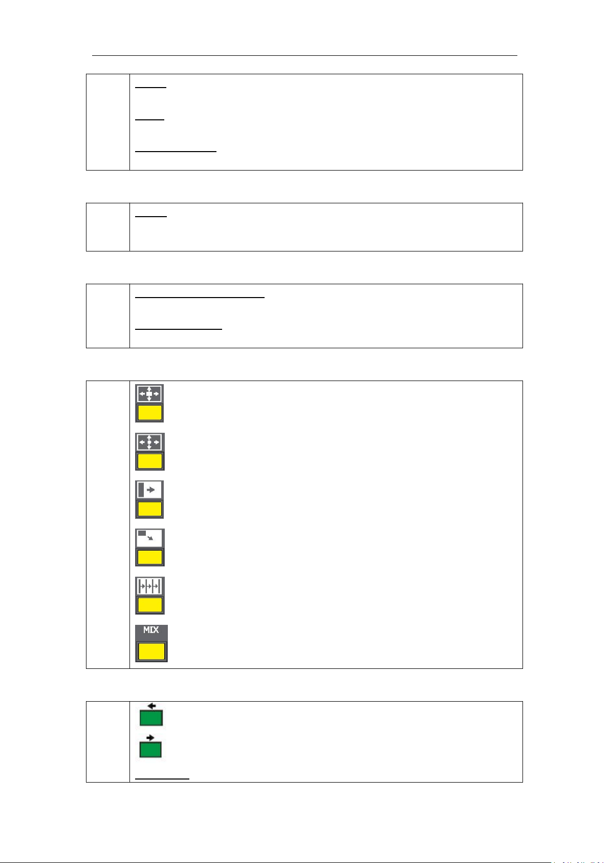
OSD Edit Area
16
: The button to enable subtitle to scroll from right to left.
: The button to enable subtitle to scroll from left to right.
OSD TAKE

11
Subtitles switch button.
Switch Mode Area
17
CUT
Seamless switching.
TAKE
Seamless switching with effect.
T-BAR
WIPE and fade switching.
12
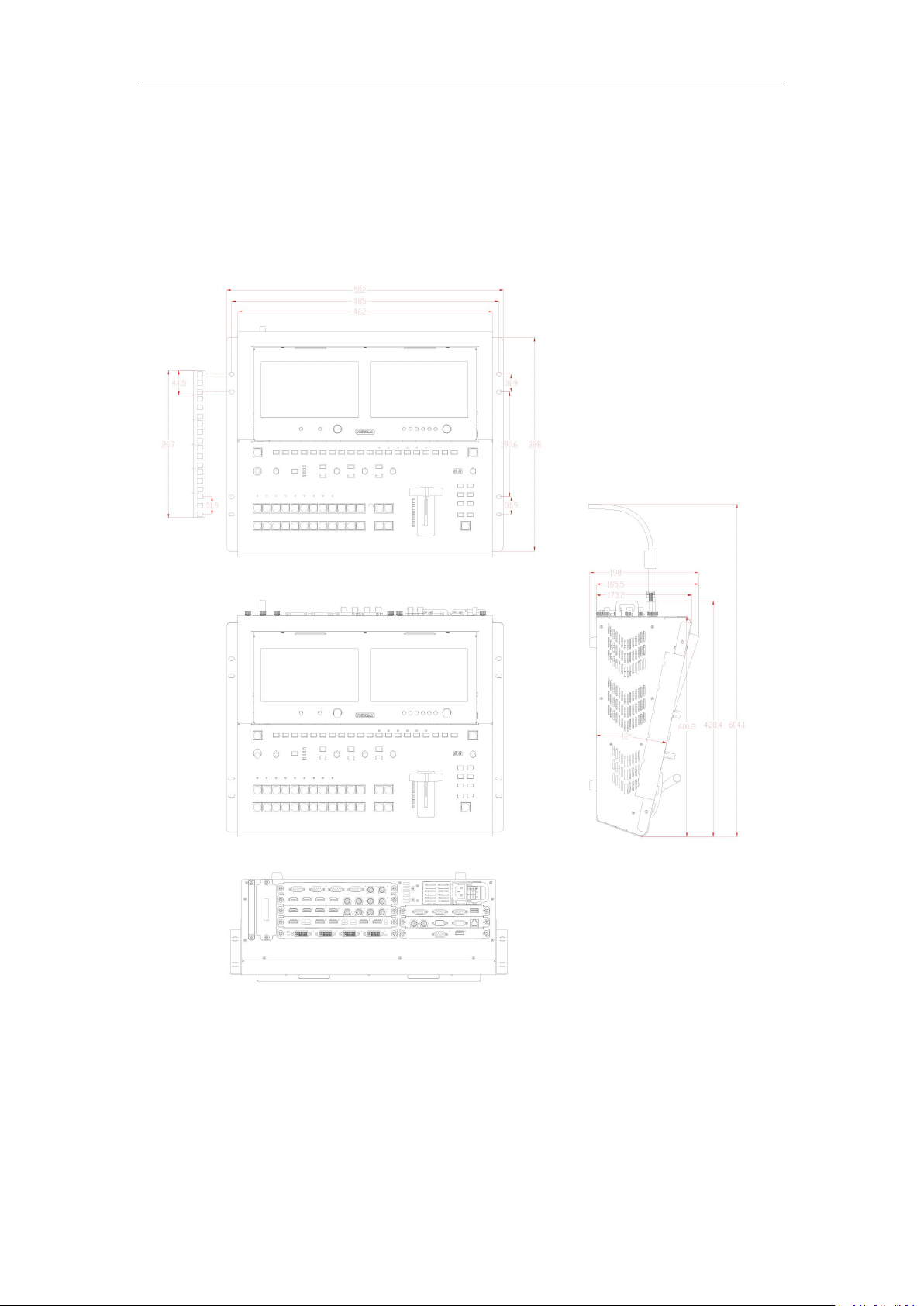
1.2.3 Dimension
Following is the dimension of M3:
13
Chapter 2 Installing Your Product
2.1 Plugging in Signals
Connect signals to the product (ensure all devices are powered off first). Tighten connector
screws/locks where provided.
2.2 Plugging in Main Power
Connect IEC cable to device and plug into wall socket. Turn on power at wall socket.
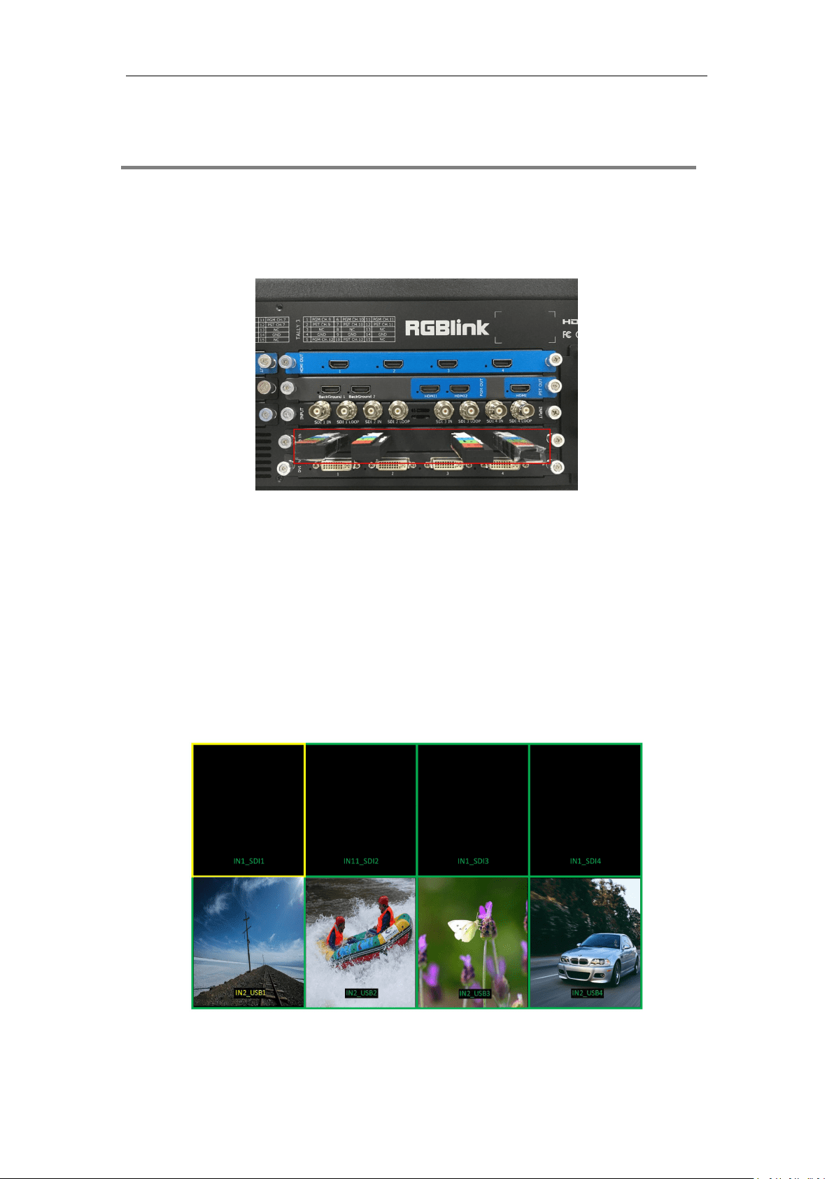
2.3 Turning on Your Product
When red light of [POWER] button is on, the device is standby.
Press [POWER] button for 3 seconds, the light will turn yellow and the device is starting up. After
10 seconds, the PVW monitor display the preview signals, as shown in the picture below:
14
Chapter 3 Using Your Product
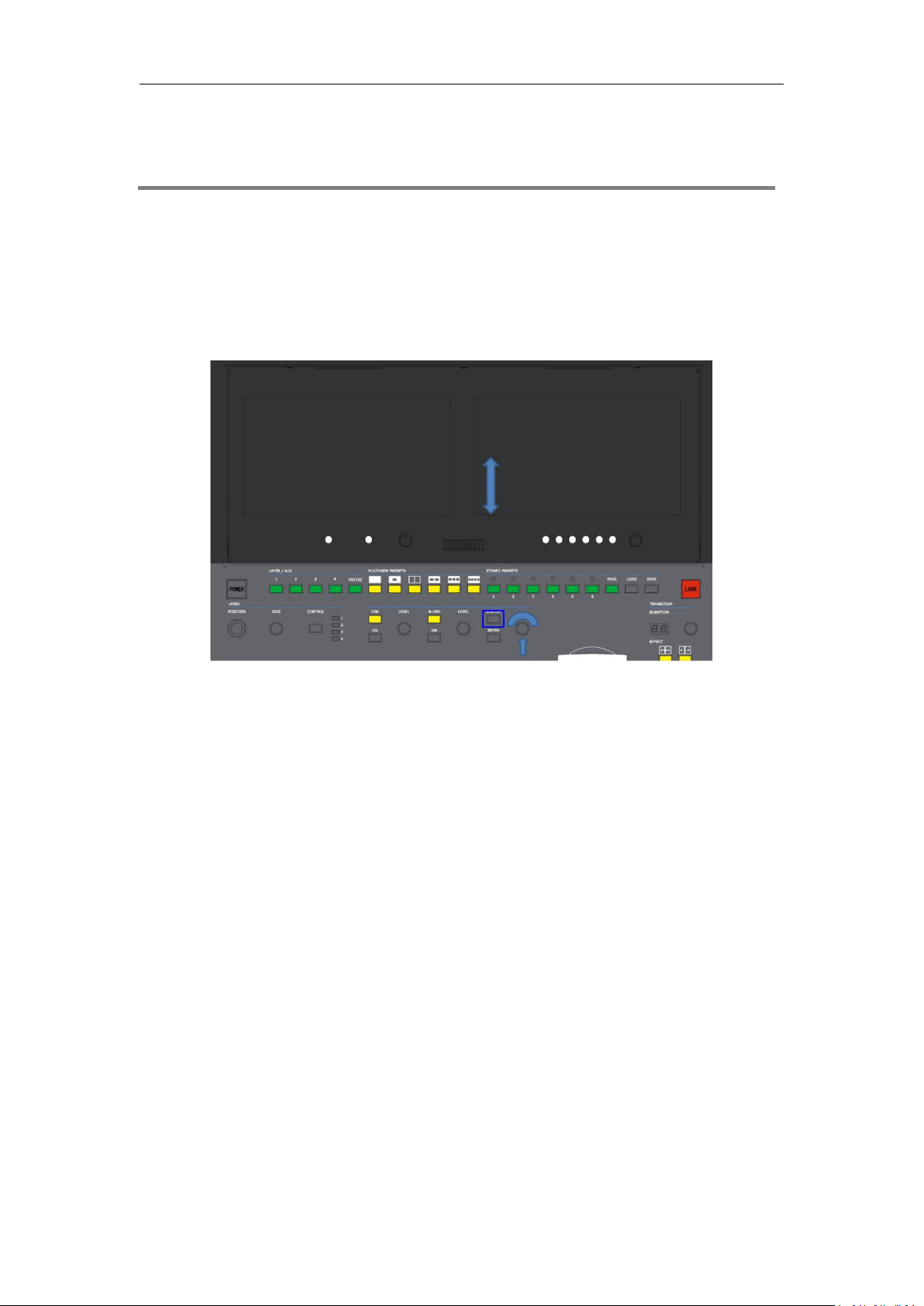
3.1 Using the MENU Button
Press [SYSTEM] button to enter the menu display.
Turn the rotary knob to navigate to the menu item required. The option with green background
refers to the current item. Press the knob to select and get into the menu item.
As shown in the figure below:
16
Chapter 3: Using Your Product
17
3.3 Using the Menu
Use the menu system for convenient and intuitive operation. The 8 inch HD monitor shows the
menu items. The monitor shows the default state when the menu is not in use, or the operation
has timed out. Using the SYSTEM button and rotary knob in the top panel, the PGM monitor will
show the corresponding menus according to user selections.
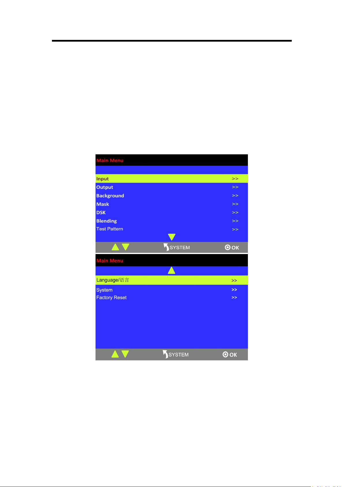
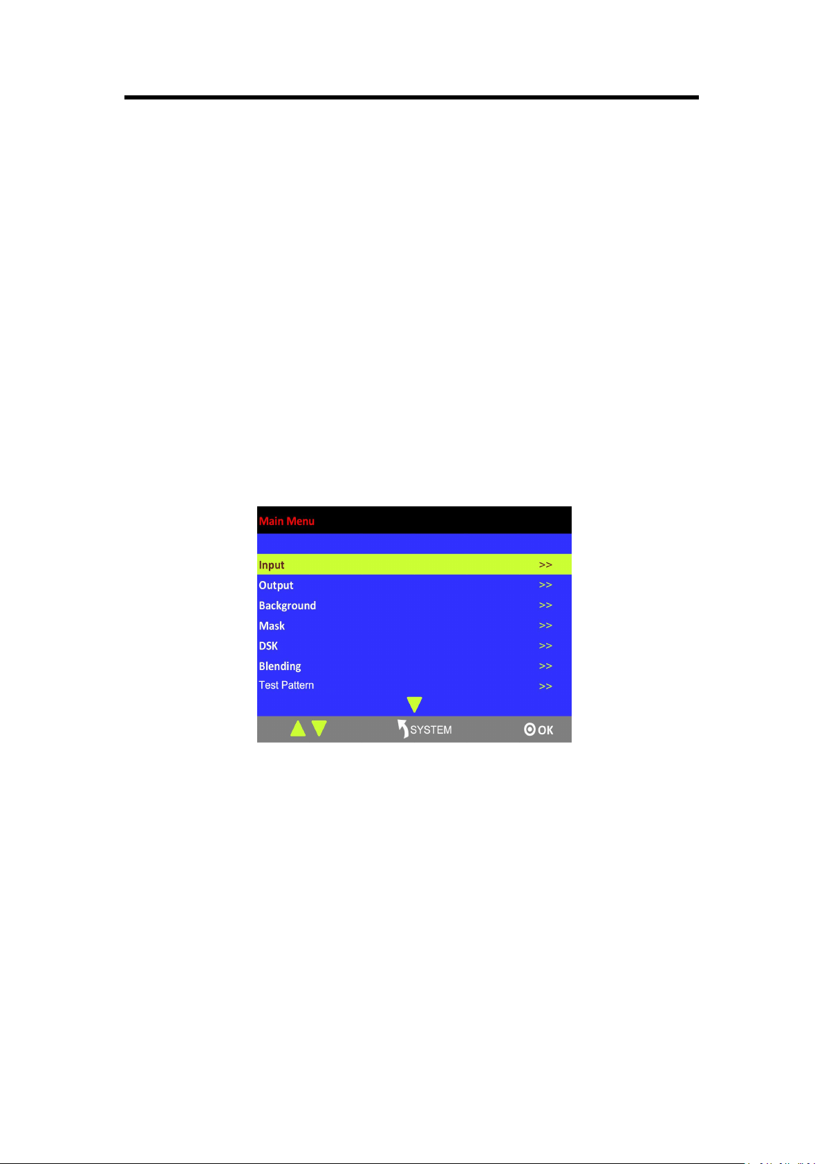
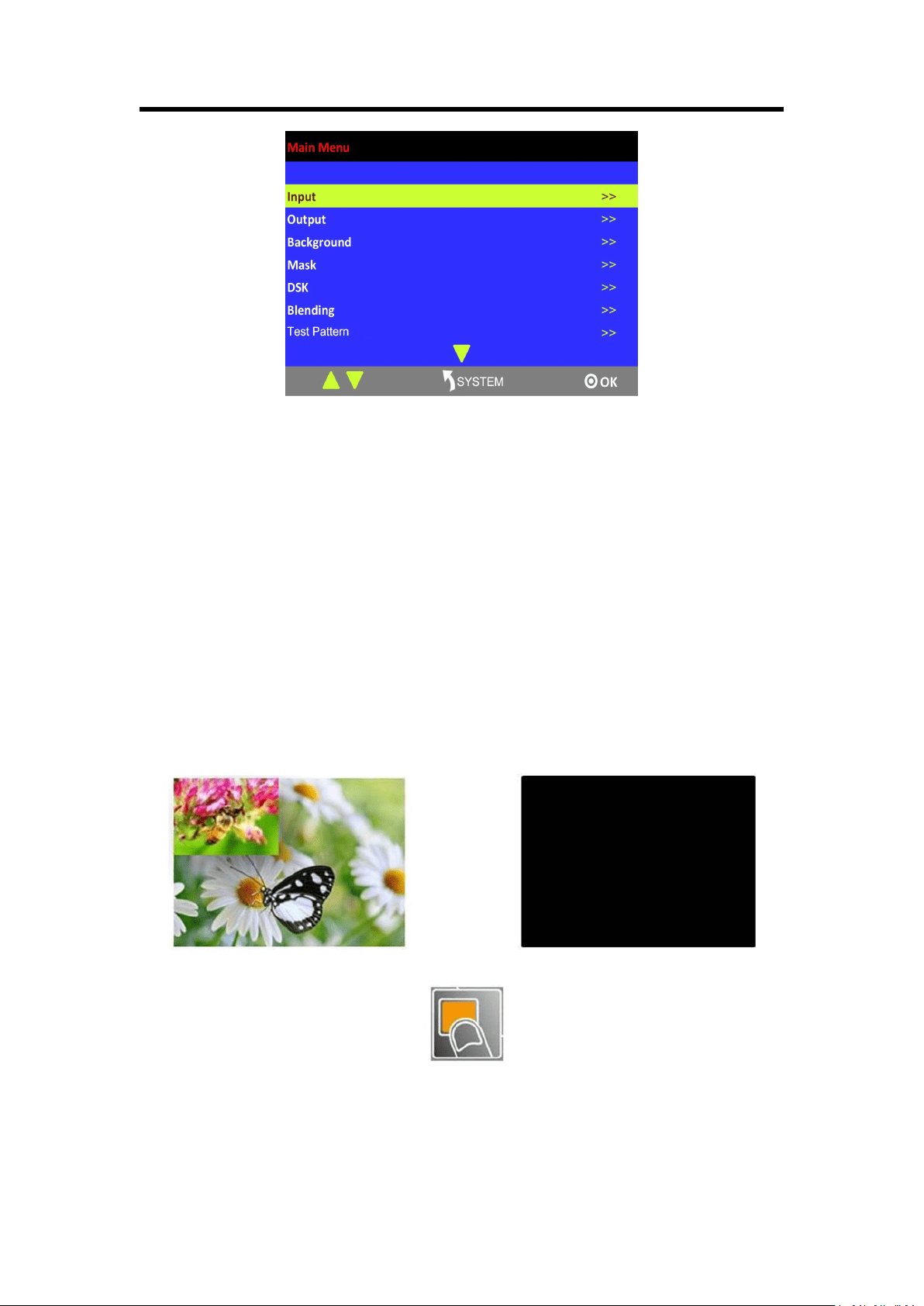
3.3.1 Understanding the Main Menu
Press [SYSTEM] button in the default state and turn the rotary knob, the PGM monitor will show
the main menus as below:
There are 10 items in the main menu, and are displayed in 2 pages. Press [ENTER] button, and
select any menu above. Press the rotary knob to confirm, the LCD display will show the submenu.
The [SYSTEM] button is also the [Return] button.
Chapter 3: Using Your Product
18
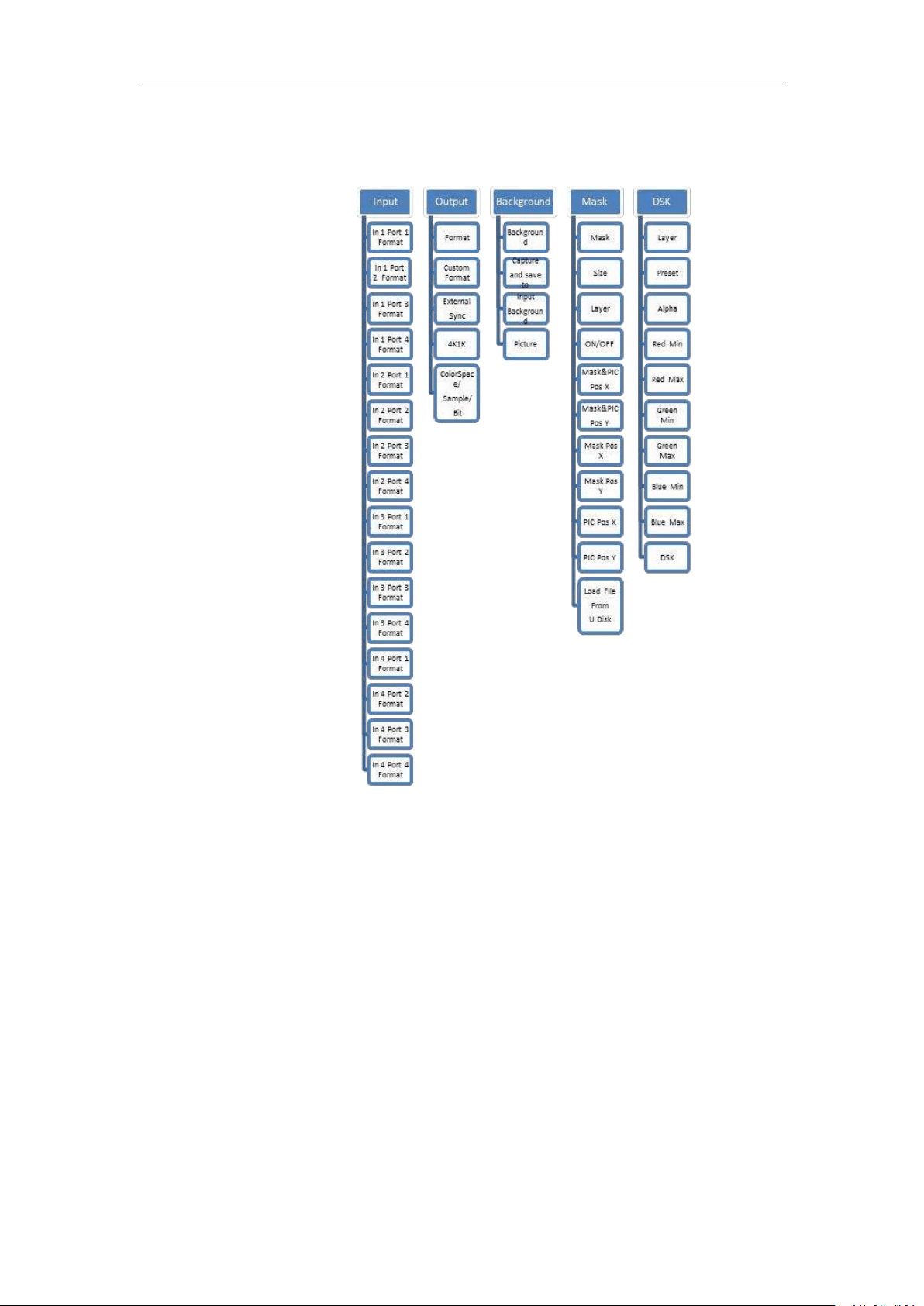
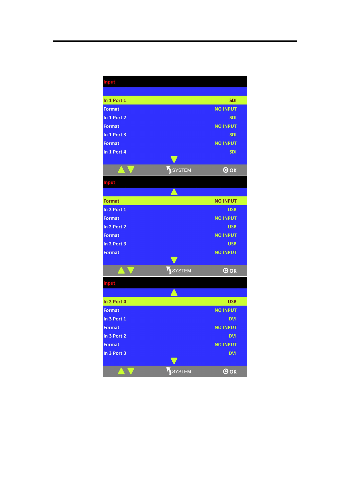
3.3.2 Input Menu
Chapter 3: Using Your Product
19
Input and port
Show the input card and port, and the corresponding signal.
Format
Show the format of the corresponding signal.
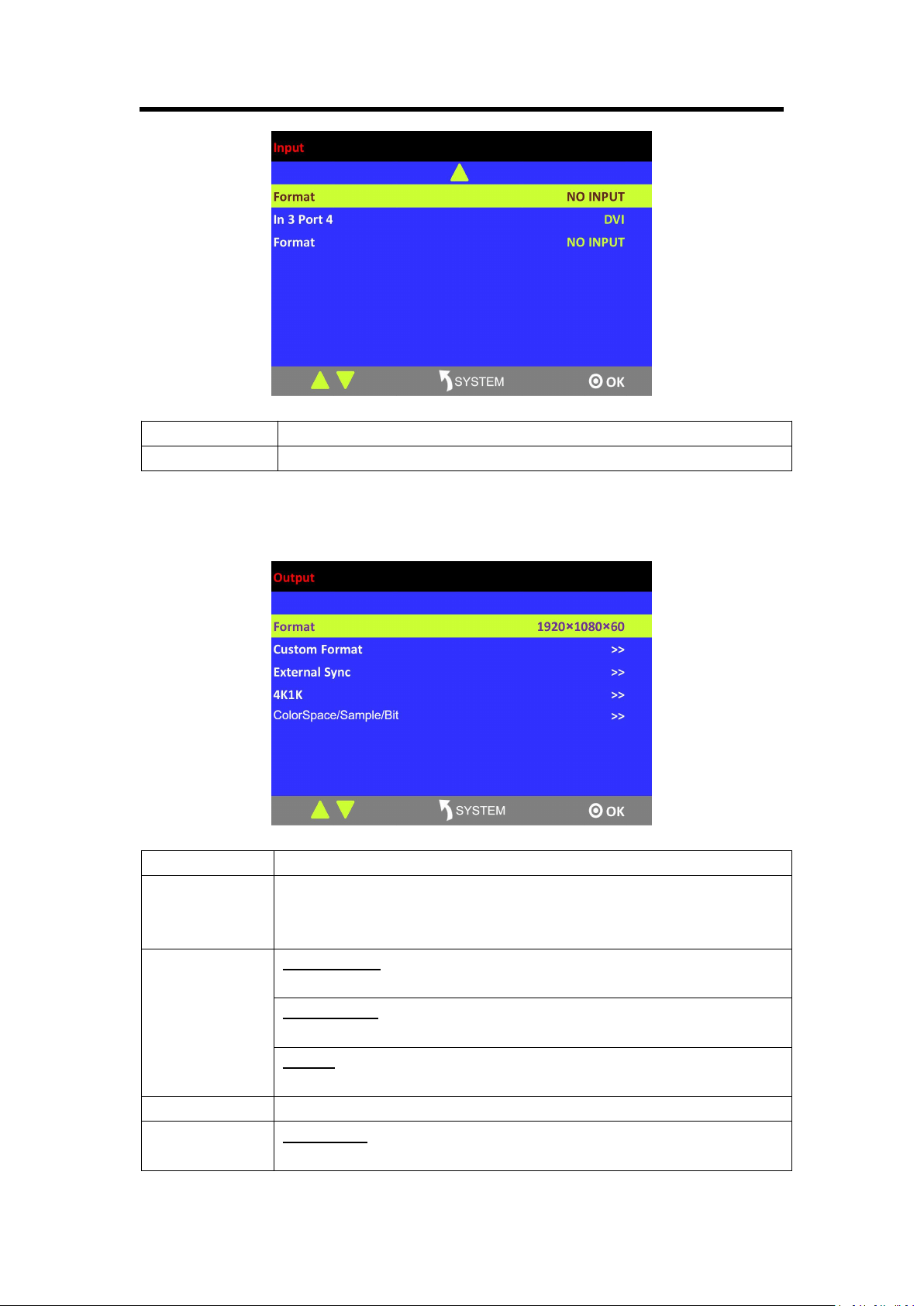
3.3.3 Output Menu
Format
There are 45 kinds of common output resolutions.
Custom Format
The special display project or LED display application would like to require
special resolution settings to meet the requirement (refer to Custom Output
Resolution).
External Sync
External Sync
Select “ON” or “OFF” to enable or disable external sync function.
Input Format
Show the input format of external sync.
Format
Set the format of external sync.
4K1K
Enable or disable the 4K1K function.
ColorSpace/Sam
ple/Bit
Output port
It includes 7 output ports: PGM1, PGM2, PST, AUX1, AUX2, AUX3 and
Chapter 3: Using Your Product
20
AUX4. [Note that AUX appearing in the product (V1.02 with new board) is
actually AUX mentioned in this manual. We will update the menu for the
next version.]
Type of output ports
HDMI and DVI
Color Space
Set color space on video or image.
Brightness
Range: 0~128
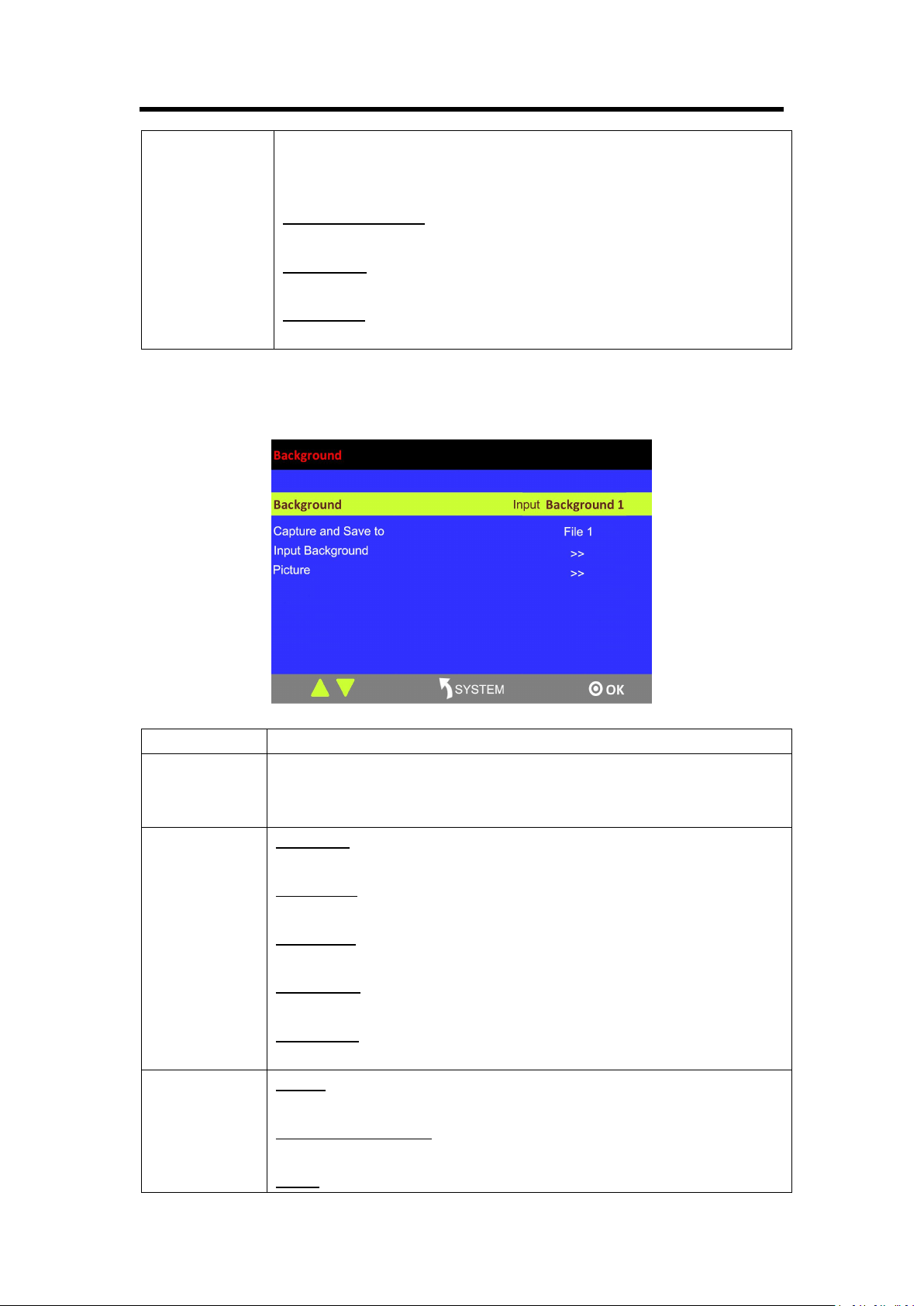
3.3.4 Background Menu
Background
Select background 1, background 2 or image.
Capture and
Save to
User can capture the current image and save it. Up to 50 images can be saved.
The same saving name will result in replacement of an image saved before.
The replacement takes effect after restart.
Input
Background
Resolution
Settings resolution.
Scale H Pos
Range: 0~31
Scale V Pos
Range: 0~31
Scale H Size
Set the horizontal size.
Scale V Size
Set the vertical size.
Picture
Picture
Select a saved image.
Load File from U Disk
User can load a document by U disk.
Delete
Chapter 3: Using Your Product
21
Delete an image.
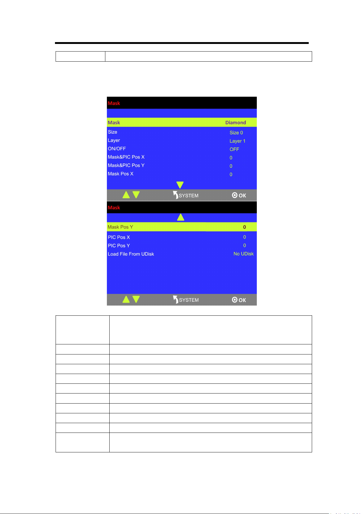
3.3.5 MASK Menu
Mask
Support 13 kinds of masks: diamond, round, heart, star, triangle, oval,
hexagons, pentagon, 4 point star, 6 point star, lighting, crescent left and
crescent right
Size
Set the size of mask.
Layer
Select the layer.
ON/OFF
Select “ON” or “OFF” to enable or disable mask function.
Mask&PIC Pos X
Set the horizontal position of effect and picture.
Mask&PIC Pos Y
Set the vertical position of effect and picture.
Mask Pos X
Set the horizontal position of effect.
Mask Pos Y
Set the vertical position of effect.
PIC Pos X
Set the horizontal position of picture.
PIC Pos Y
Set the vertical position of picture.
Load File From
UDisk
User can load customized effect image from UDisk.
Chapter 3: Using Your Product
22
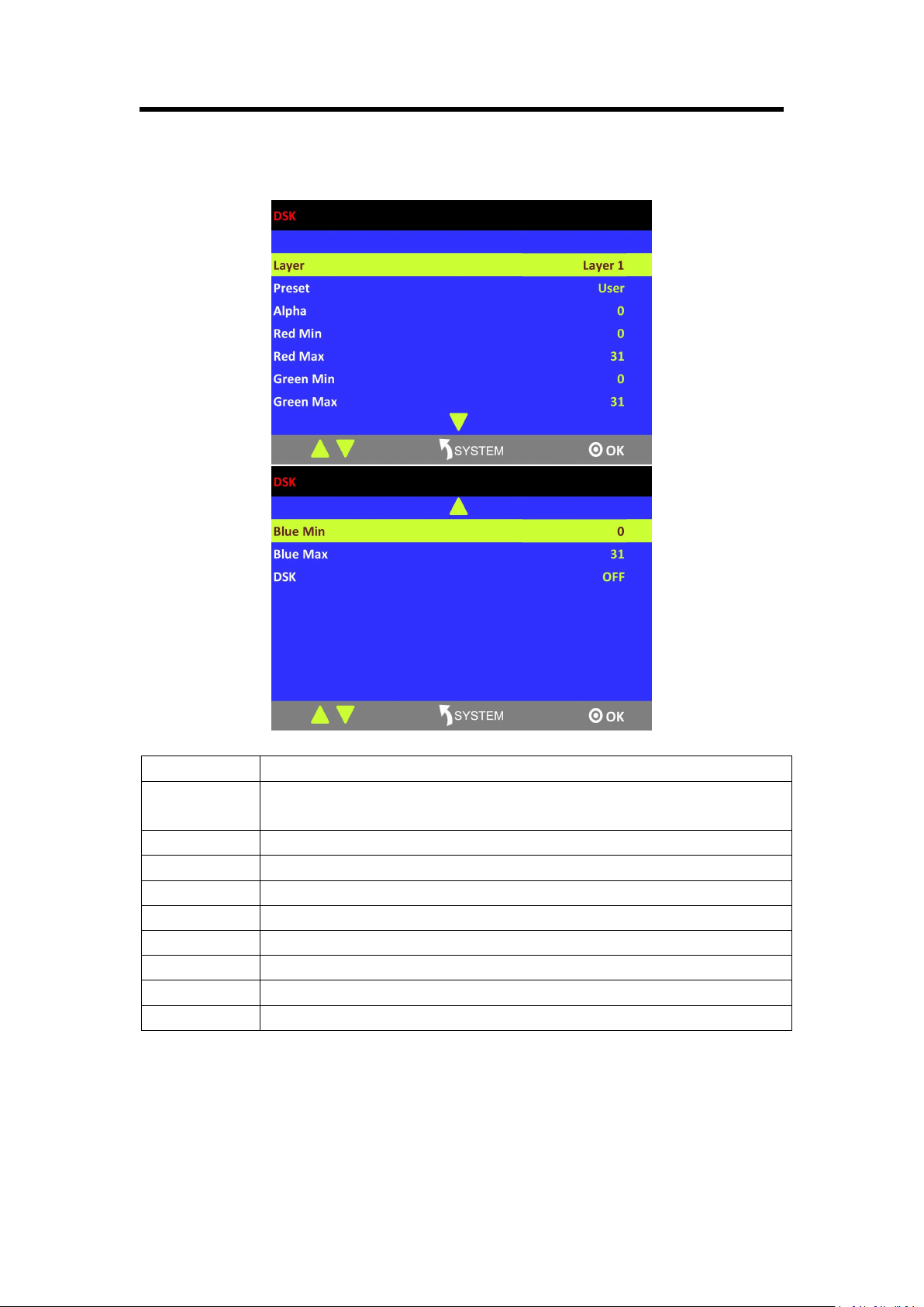
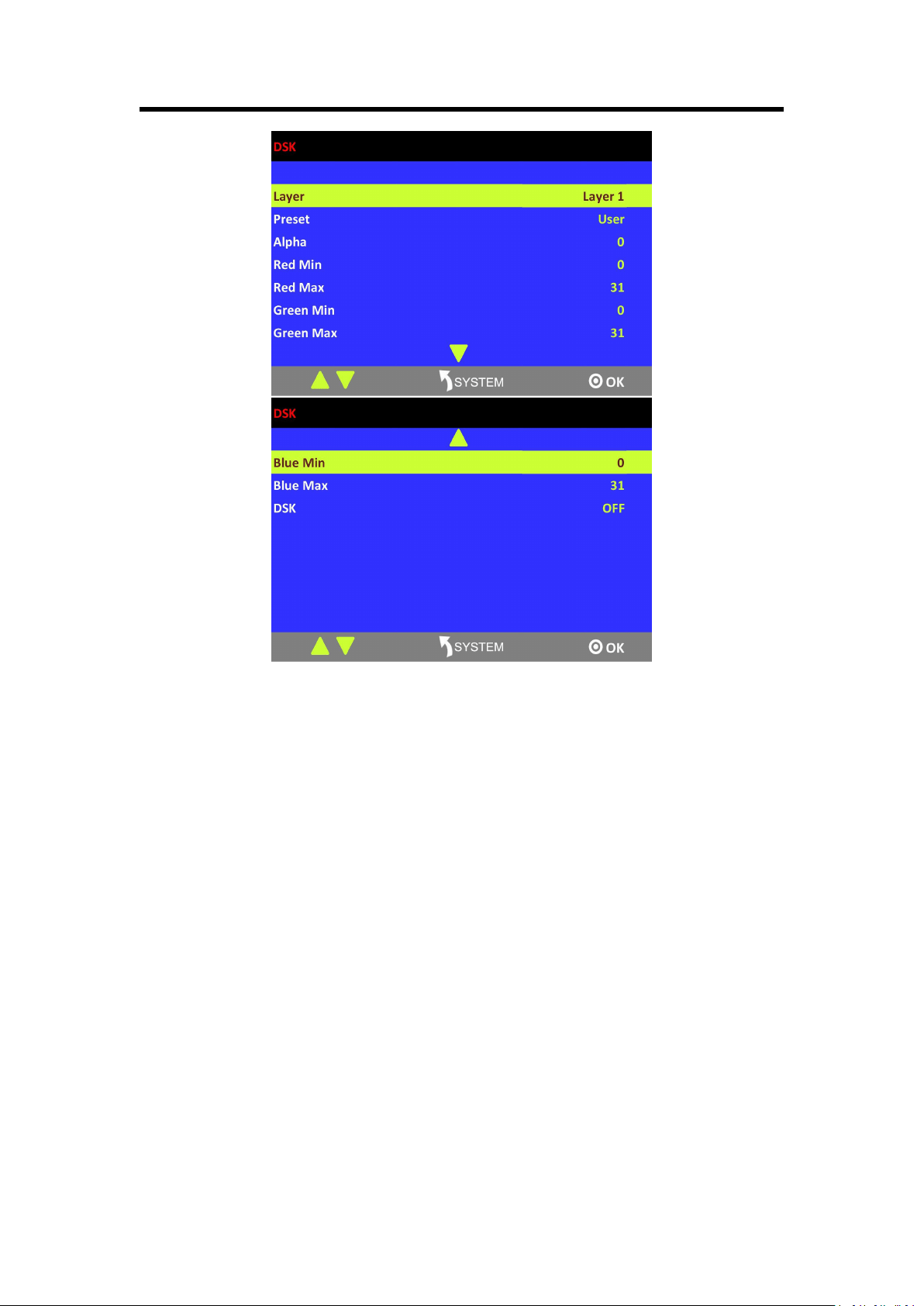
3.3.6 DSK Menu
Layer
Select the layer.
Preset
Select user, black background, green background, blue background, red
background and white background.
Alpha
The adjustment range is between 0~128.
Red Min
The adjustment range is between 0~255.
Red Max
The adjustment range is between 0~255.
Green Min
The adjustment range is between 0~255.
Green Max
The adjustment range is between 0~255.
Blue Min
The adjustment range is between 0~255.
Blue Max
The adjustment range is between 0~255.
DSK
Select “ON” or “OFF” to enable or disable DSK function.
Chapter 3: Using Your Product
23
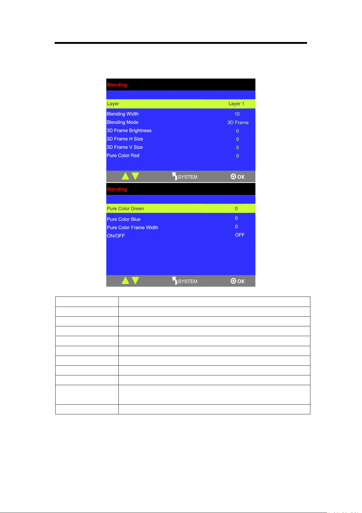
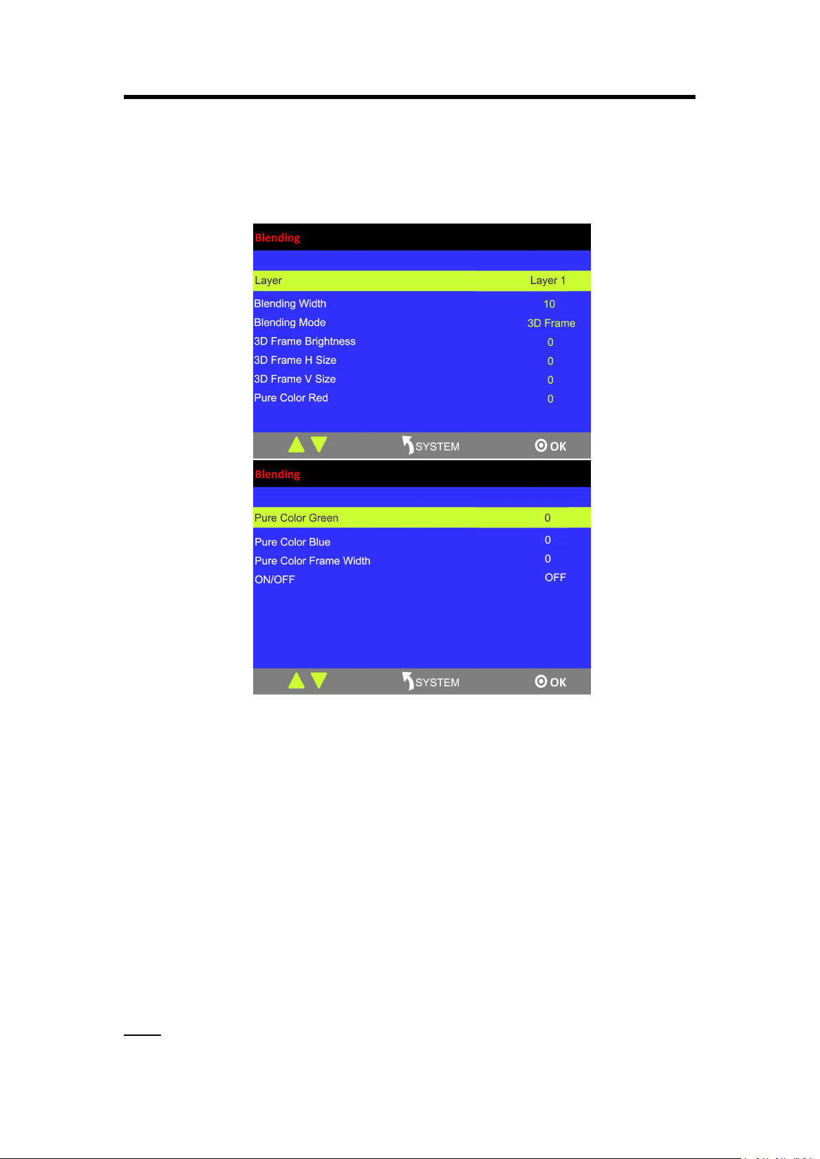
3.3.7 Blending Menu
Layer
Select the layer.
Blending Width
Set the blending width, the adjustment range is between 1~90.
Blending Mode
3D Frame, Pure Color Frame, Inline and Outside can be selected.
3D Frame Brightness
Range: 0~255
3D Frame H Size
Range: 0~127
3D Frame V Size
Range: 0~127
Pure Color Red
Range: 0~255
Pure Color Green
Range: 0~255
Pure Color Blue
Range: 0~255
Pure Color Frame
Width
Range: 0~23
ON/OFF
Turn on or turn off the function.
Chapter 3: Using Your Product
24
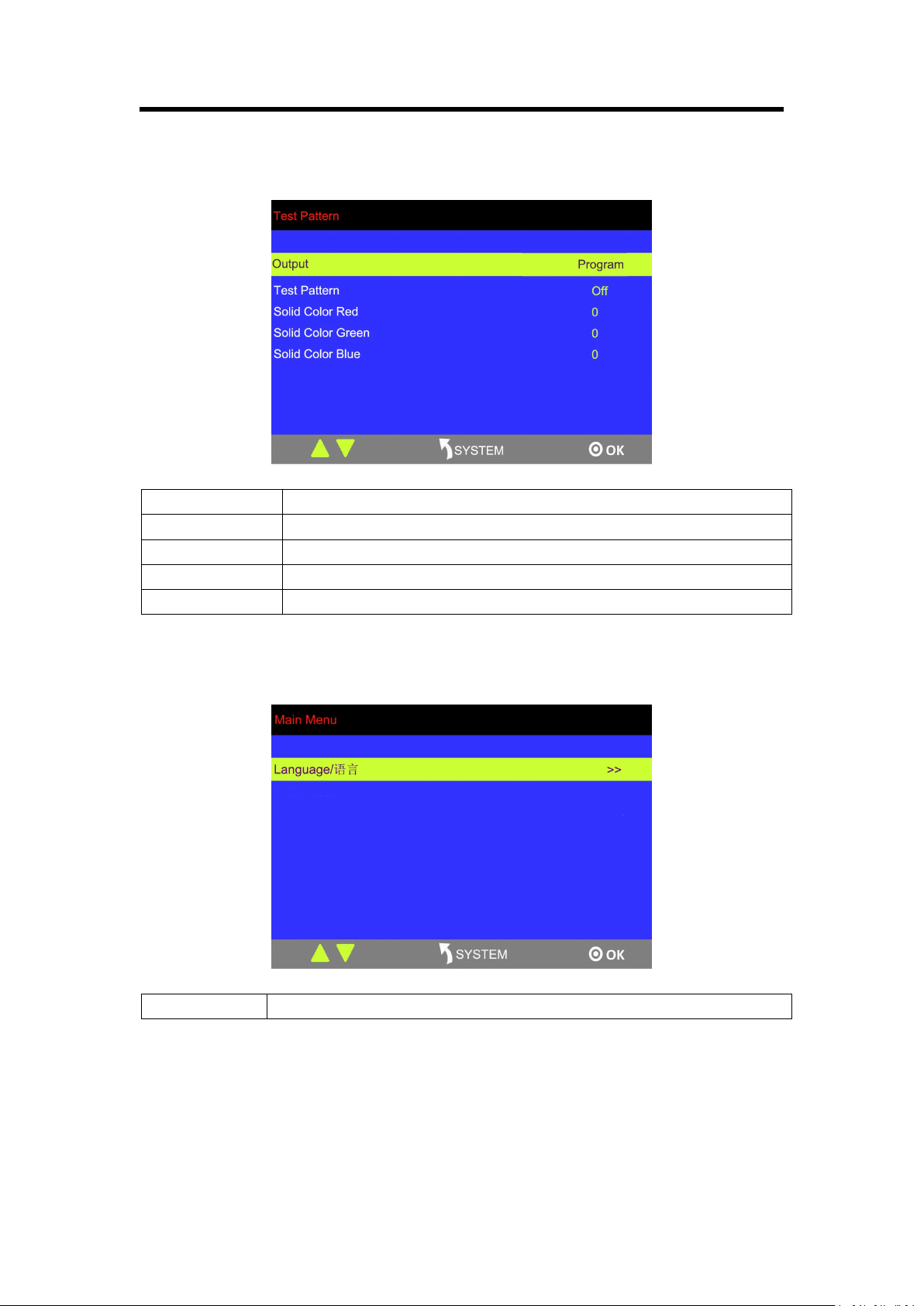
3.3.8 Test Pattern
Output
Select program or preview
Test pattern
Select solid color, color bar or off.
Solid Color Red
Range: 0~255
Solid Color Green
Range: 0~255
Solid Color Blue
Range: 0~255
3.3.8 Language Menu
Language
Select Chinese or English.
Chapter 3: Using Your Product
25
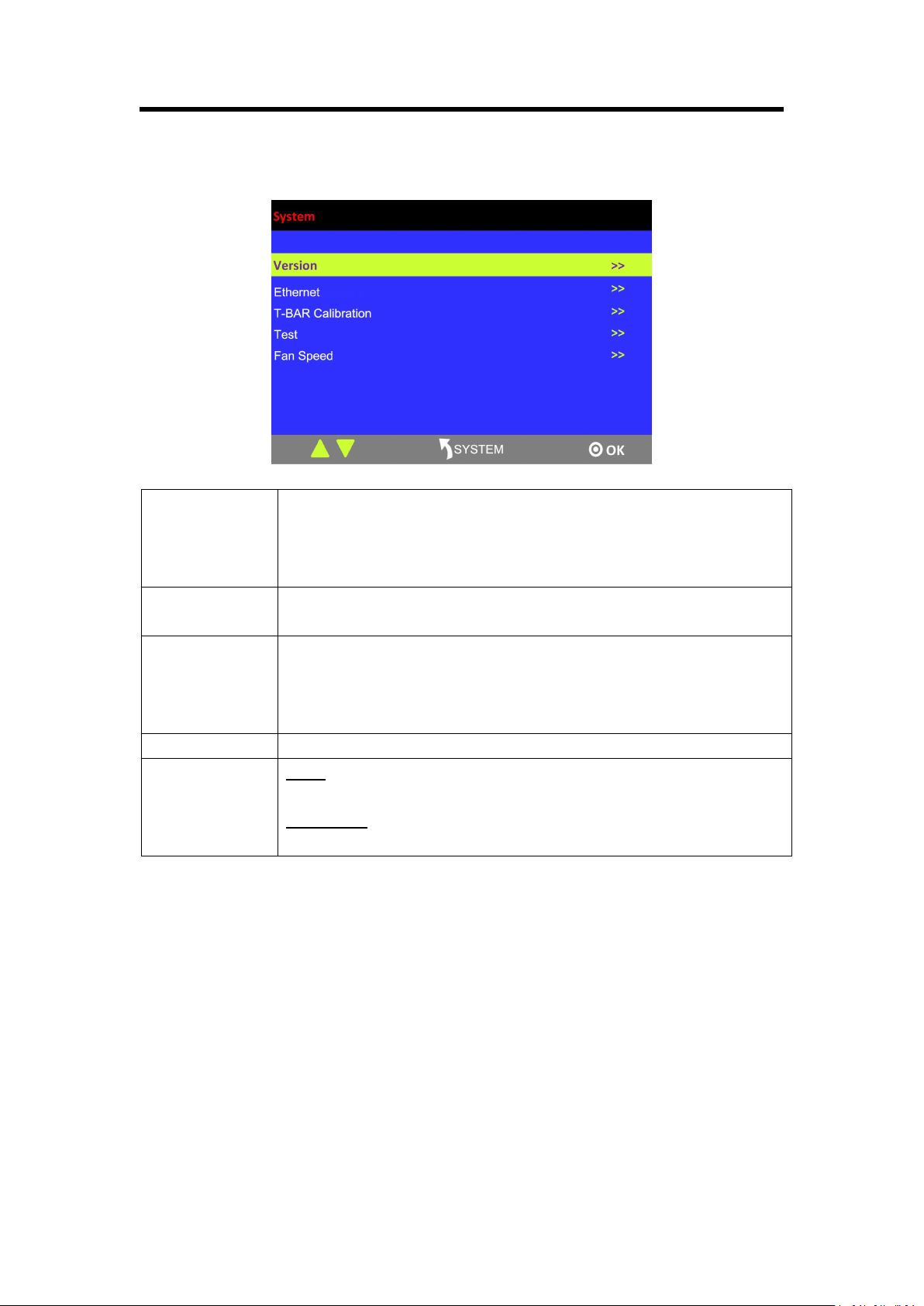
3.3.9 System Menu
Version
Show the version of LCD, COM, PVW MCU, PVW FPGA, PGM MCU,
PGM FPGA, Optional In 1 MCU, Optional In 1 FPGA, Optional In 2
MCU, Optional In 2 FPGA, Optional In 3 MCU, Optional In 3 FPGA,
Optional Out MCU and Optional Out FPGA.
Ethernet
Turn on or turn off DHCP. User can edit IP and default gateway and check
subnet mask.
T-BAR
Calibration
Step 1: Press the T-BAR to the top.
Step 2: Choose ON.
Step 3: Press the T-BAR to the bottom.
Step 4: Choose ON.
Test
Enable or disable the LED test function and adjust the key value.
Fan Speed
Mode
Auto or custom.
Fan Speed
Range: 50~100
Chapter 3: Using Your Product
26
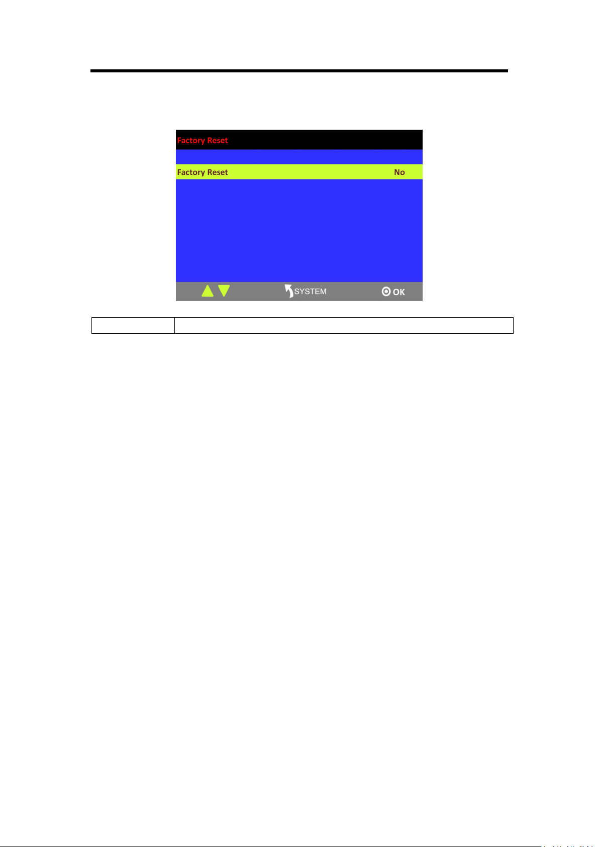
3.3.10 Factory Reset Menu
Factory Reset
Select “YES” or “NO”. Select “YES” to restore default settings.

Chapter 3: Using Your Product
27
3.4 PVW
M3 has an 8 inch HD monitor (HDMI preview or VGA preview), and it supports the functions
below:
1. Select any 8 channels from the 12 channels.
2. Quickly switch between single image preview and eight-image preview by pressing [PVW]
button.
3. Source name synchronization, and automatically recognition for different input modules.
4. Color indicator of source name. Green for preview; yellow for preset and red for program
3.5 PST
M3 has an 8 inch HD preview display, and one HDMI preview output, it has following functions:
3.5.1 Signal Selection
Press any button in Input Sources Area. For example, press the button [5], the border of signal 5
will turn yellow, and the signal in PGM monitor will be switched to signal 5.
3.5.2 Add or Delete Layer
Press any button of [1] to [4] in Layer/Aux Area to add or delete a layer.
Add layer: The light is on.
Select layer: The light is flashing.
Delete layer: The light is off.
3.5.3 Freeze the Layer
Press [FREEZE] button in Layer/Aux Area, the layer will be frozen. Press the button again, and the
layer restores.
3.5.4 Multiview Presets
1. Press any button in Multiview Presets Area to select multiview layouts, including 1P, PIP CENT,
SIDE BY SIDE, 3P, 4P and 5P.
2. Press [CONTROL] button in Position, Size and Control Area to select the layer, different signals
can be used as the layer.
3. User can adjust the position, size, crop for the selected layer, and set DSK, BLEND and MASK.
Chapter 3: Using Your Product
28
3.5.5 Set the Position
1. Press [CONTROL] button in Position, Size and Control Area to select a layer, the border of the
selected layer will turn green.
2. Swing the [POSITION] joystick in Position, Size and Control Area to adjust the position of the
layer.
Swing the joystick to the left or right to change the horizontal position.
Swing the joystick up or down to change the vertical position.
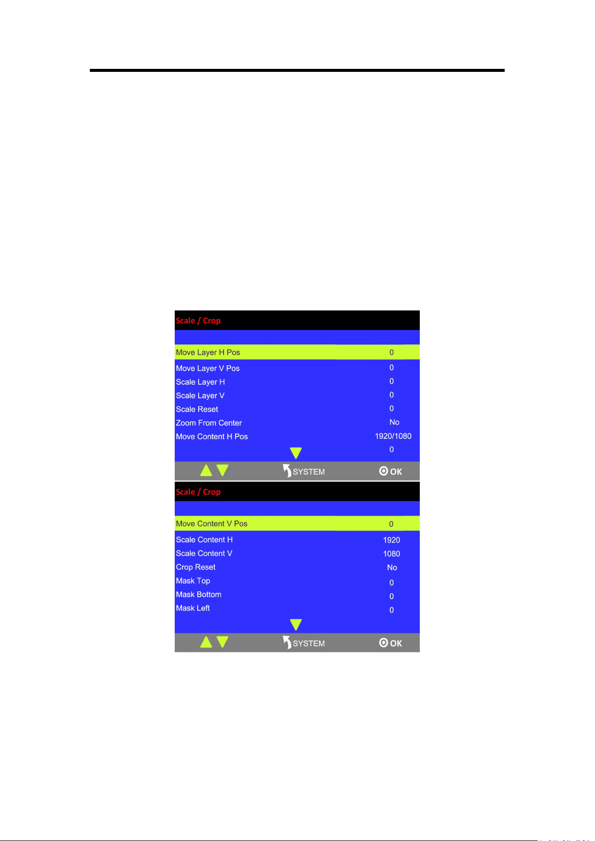
3.5.6 Scale and Crop
Press [SIZE] button in Position, Size and Control Area, and get into the interface as follows:

Chapter 3: Using Your Product
29
Move Layer H Pos: Adjust the horizontal position of layer.
Move Layer V Pos: Adjust the vertical position of layer.
Scale Layer H: Adjust the width of layer.
Scale Layer V: Adjust the height of layer.
Scale Reset: Reset button.
Zoom From Center: Zoom the width and height in equal proportion.
Move Content H Pos: Crop the horizontal position of layer.
Move Content V Pos: Crop the vertical position of layer.
The layer will be displayed in full screen after being cropped
Scale Content H: Set the width for cropping, and the cropped layer will be displayed in full screen.
Scale Content V: Set the height for cropping, and the cropped layer will be displayed in full
screen.
Crop Reset: Reset button.
The layer will not be displayed in full screen after being cropped
Mask Top: Crop the top, and the layer will not be displayed in full screen.
Mask Bottom: Crop the bottom, and the layer will not be displayed in full screen.
Mask Left: Crop the left, and the layer will not be displayed in full screen.
Mask Right: Crop the right, and the layer will not be displayed in full screen.
Reset Mask: Reset button.
Exit: ESC button to stop settings size/crop.
3.5.7 DSK Settings
1. Firstly, enable the multiview function.
2. Press [SYSTEM] button, and get into the menu items. Turn the rotary knob, and select <DSK>,
press the knob to confirm. (Or press [DSK] button to get to the DSK menu items)
Chapter 3: Using Your Product
30
Layer: Select the layer for DSK.
Preset: Select user, black background, green background, blue background, red background or
white background.
Alpha: The adjustment range is between 0~128.
Red Min: The adjustment range is between 0~255.
Red max: The adjustment range is between 0~255.
Green Min: The adjustment range is between 0~255.
Green Max: The adjustment range is between 0~255.
Blue Min: The adjustment range is between 0~255.
Blue Max: The adjustment range is between 0~255.
DSK: Can select enable or disable the DSK function.
3.5.8 BLEND Settings
M3 has 4 blending modes – 3D Frame, Pure Color Frame, Inline and Outside.
Note:
3 modes can be selected for the same layer simultaneously. However, Inline and Outside cannot
be edited on the same layer at the same time. That is, user can select 3D Frame, Pure Color
Frame and Inline, or 3D Frame, Pure Color Frame and Outside at a time.
Chapter 3: Using Your Product
31
Follow the steps as below:
(1) Select multiview mode first, or BLEND is not available.
(2) Press [BLEND] button and get into the menu as below:
Layer: Select target layer.
Blending Width: The adjustment range is 1~90.
Blending Mode: Inline, Outside, 3D Frame and 3D Pure Frame
3D Frame Brightness: The adjustment range is 0~255.
3D Frame H Size: The adjustment range is 0~127.
3D Frame V Size: The adjustment range is 0~127.
Pure Color Red: The adjustment range is 0~255.
Pure Color Green: The adjustment range is 0~255.
Pure Color Blue: The adjustment range is 0~255.
Pure Color Frame Width: The adjustment range is 0~23.
ON/OFF: Turn on or turn off BLEND.
Follow the operating steps of each mode below:
Inline:
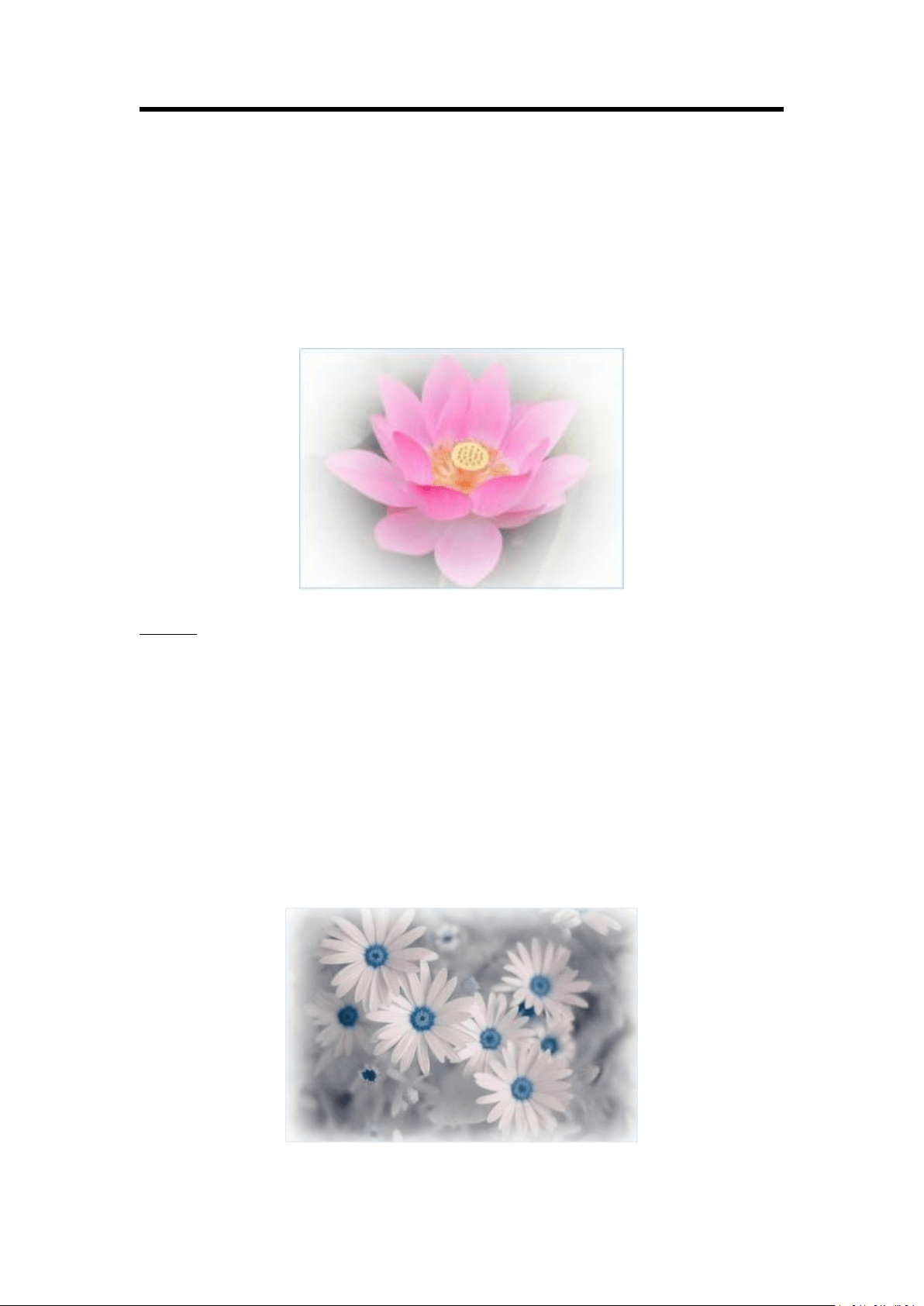
Chapter 3: Using Your Product
32
Press [SYSTEM] button and get into the main menu. Rotate the rotary button and select [BLEND].
Also, user can press the shortcut button in the [BLEND] area.
Layer: select target layer
Blending Mode: Inline
Blending Width: 1~90
ON/OFF: select ON to enable the function
See the effect as below:
Outside:
Press [SYSTEM] button and get into the main menu; select [Blending]. Or just press [BLEND]
button.
Layer: select target layer
Blending Mode: Outside
Blending Width: 1~90
ON/OFF: select ON to enable the function
See the effect as below:
Chapter 3: Using Your Product
33
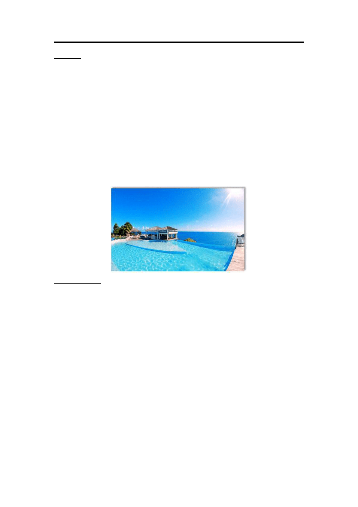
3D Frame:
Press [SYSTEM] button and get into the main menu; select [Blending]. Or just press [BLEND]
button.
Layer: select target layer
Blending Width: 1~90
Blending Mode: 3D Frame
3D Frame Brightness: 0~255
3D Frame H Size: 0~127
3D Frame V Size: 0~127
ON/OFF: select ON to enable the function
See the effect as below:
Pure Color Frame:
Layer: select target layer
Blending Width: 1~90
Pure Color Red: 0~255
Pure Color Green: 0~255
Pure Color Blue: 0~255
Pure Color Frame Width: 0~23
ON/OFF: select ON to enable the function
See the effect as below:
Chapter 3: Using Your Product
34
3.5.9 WIPE Settings
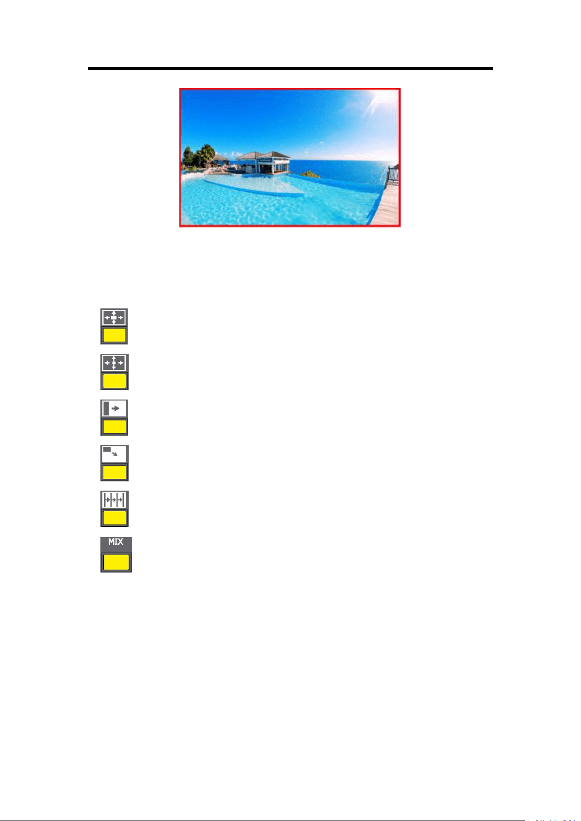
1. Press the WIPE buttons in WIPE Operation Area, M3 has 14 kinds of wipe modes:
: Iris box: ←□→, →□←, ←+→, →+←, L←M→R, and T←M→B.
: Iris round.
: WIPE: R→L, L→R.
: Push to bottom right: T→B, B→T, LT→RB.
: Blinds vertical
: Fade mode
2. Press [TAKE] button, or use T-bar switcher to switch the image to program with selected wipe.
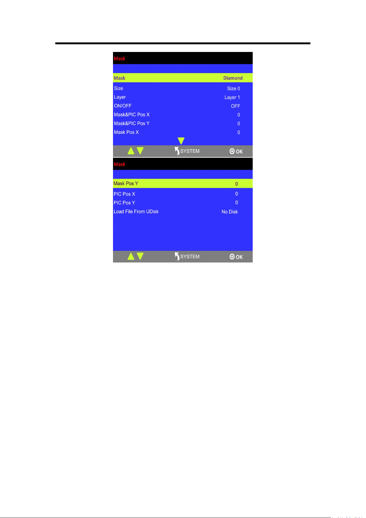
3.5.10 Mask Settings
1. Press [SYSTEM] button, and get into the menu items.
2. Turn the rotary knob, and select <Mask>, press the knob to confirm:
Chapter 3: Using Your Product
35
Enable the mask function:
Turn the rotary knob and select “ON” from <ON/OFF> to enable the mask function.
Select effect:
Turn the knob, and select <MASK>, press the knob to confirm. Turn the rotary knob, and
select one of the masks: diamond, round, heart, star, triangle, oval, hexagons, pentagon, 4
point star, 6 point star, lighting, crescent left and crescent right.
Mask settings:
M3 supports user-defined masks loaded from U Disk, and set the selected layer, including
effect & PIC Pos X, Y, effect X, Y, PIC Pos X, Y.
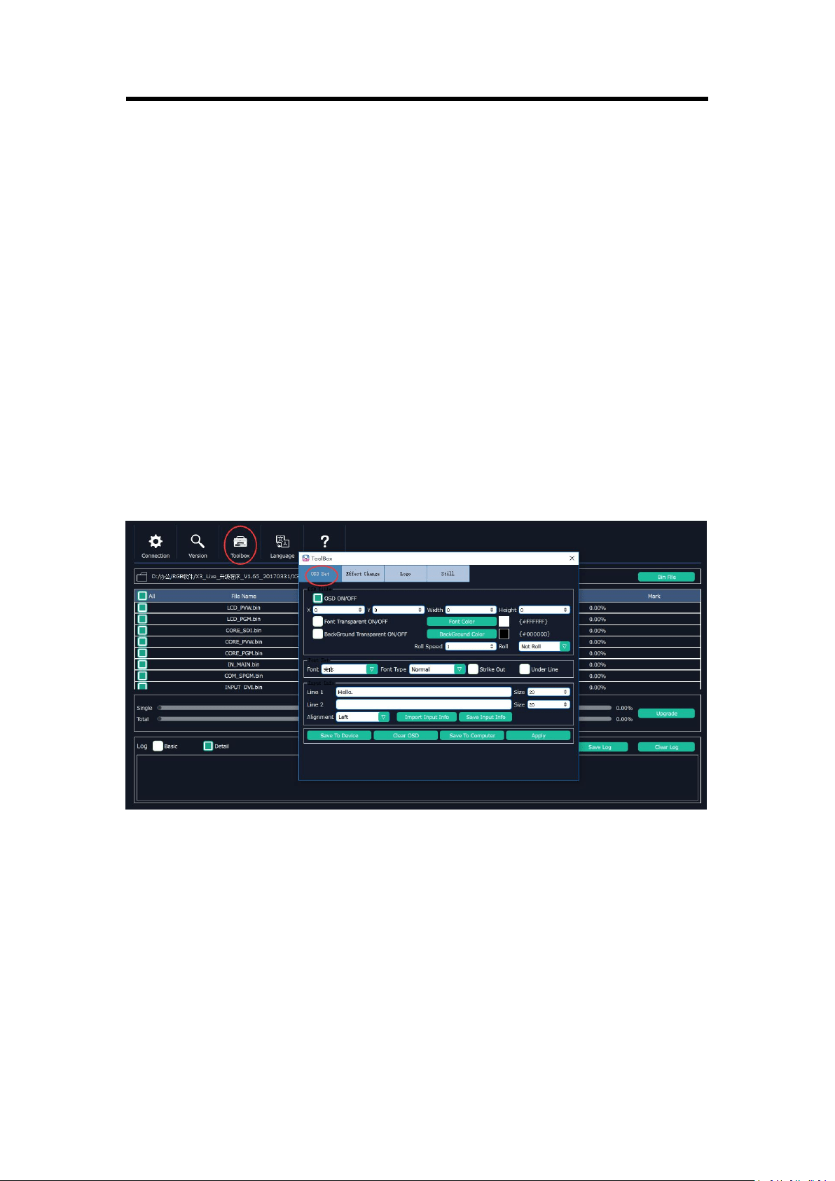
3.5.11 Custom OSD on XTOOL
User can custom 200 subtitles at a time on XTOOL.
Follow the steps below:
Tick OSD ON/OFF.
Set the parameters as needed.
Note:
- Up to two lines of OSD can be displayed on a page at a time.
Chapter 3: Using Your Product
36
- The font settings can be saved in the PC, and can be reused without another editing.
After editing, load the OSD into the device. There are two ways to load.
(1) Load OSD directly with LAN cables.
- Change the COM No. of XTOOL according to the COM No. of the PC ([Management]).
If an exclamation mark appears in the COM, restart the PC.
- Click [Save To Device].
(2) Load OSD with USB
- Click [Save to Computer] and save in order (0~199).
- Save the file as M3\OSD.
There are rules to follow for saving the file:
The file No. should be 0~199 in order. Interruption is not permitted.
Save the file as M3\OSD.
The format of USB should be FAT 32.
- Press [OSD] button in the PGM/PST area.
- Select ON and “Load OSD From UDISK”.
3.5.12 Custom MASK/EFFECT on XTOOL
First of all, user should create a graphic image with Microsoft Paint. There are some rules to
follow in creating an image:
The background of the image should be white by default.
It should be 24 bit BMP and the size cannot be larger than the output resolution.
Paint one image on the canvas at a time, and it’s better to be on the top left corner.
Click TOOLBOX and select Effect Change. There are also rules to follow in saving a file:
The file number should be 14-50 in order. Interruption is not permitted.

Chapter 3: Using Your Product
37
The file should be named as M3\EFFECT.
USB format: FAT 32
- Insert the USB into the port in the COMM area at the rear panel.
- Press [SYSTEM] button, and select MASK.
- Select “Load File From UDISK”.
- Select “ON”.
- User can set the size and position of the mask.
Note:
Either MASK, BLEND or DSK can be edited for each scene. They cannot appear at the same time.
3.5.13 Custom LOGO on XTOOL
First of all, user should create a graphic image with Microsoft Paint. There are some rules to
follow in creating an image:
The background of the image should be white by default.
It should be 24 bit BMP and the dimension should be not more than 256×128.
Select the BMP file and upload. Click TOOLBOX and select LOGO.
There are rules to follow when saving the file:
The file number should be 0~50 in order. Interruption is not permitted.
The file should be named as M3\LOGO.
The format of USB should be FAT 32.
- Press [LOGO] button in the PGM/PST preview below the right LCD screen.
- Select “Load File From UDISK”.
- Select “ON”.
3.5.14 Custom STILL on XTOOL
First of all, user should create a graphic image with Microsoft Paint. There are some rules to
follow in creating an image:
The background of the image should be white by default.
It should be 24 bit BMP and the size cannot be larger than 128
×
128.
Click TOOLBOX and select STILL. There are also rules to follow in saving a file:
The file number should be 1-50 in order. Interruption is not permitted.
The file should be named as M3\STILL.
USB format: FAT 32

Chapter 3: Using Your Product
38
- Insert the USB into the port in the COMM area at the rear panel.
- Press [STILL] button in the PGM/PST area.
- Select “Load File From UDISK”.
- Select “ON”.
- User can set the size and position.
Note:
- Before making LOGO, STILL, OSD and EFFECT, customer can insert the USB disk into the port in
the COMM area at the rear panel first, it will create those file with correct name, and then use
XTOOL to custom and save to the same USB disk.
- LOGO, STILL and OSD are static layers, and they can coexist in the same layer.
- LOGO, STILL and OSD can be only used for 2K screen.
3.6 PGM Mode
1. Switch the edited PST image to program by pressing the [CUT], [TAKE] button or T-bar, and
then the PGM image will be switched to PST state, which can be edited.
2. There are 2 HDMI outputs for program, and 4Kx1K output is available.
3. The PGM image can be looped to AUX by internal loop and external loop for quick splice.
Chapter 3: Using Your Product
39
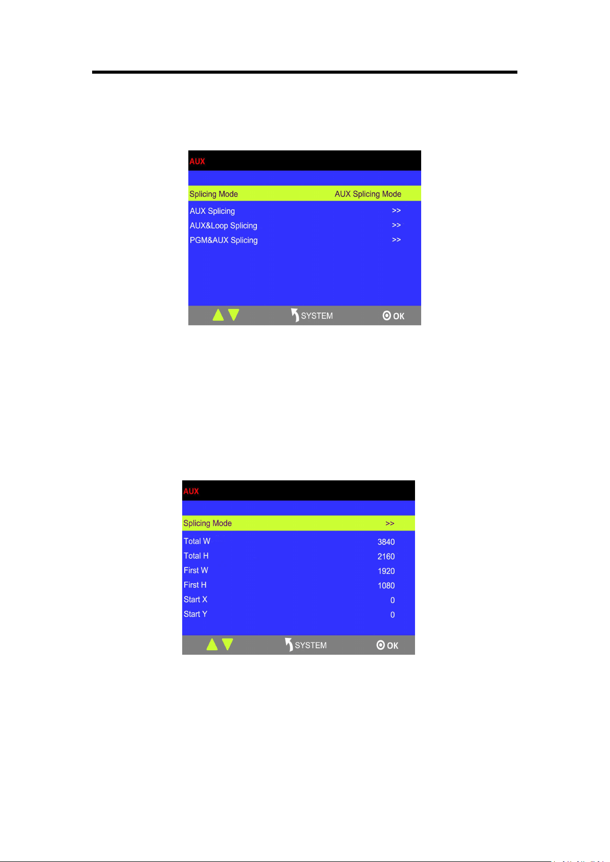
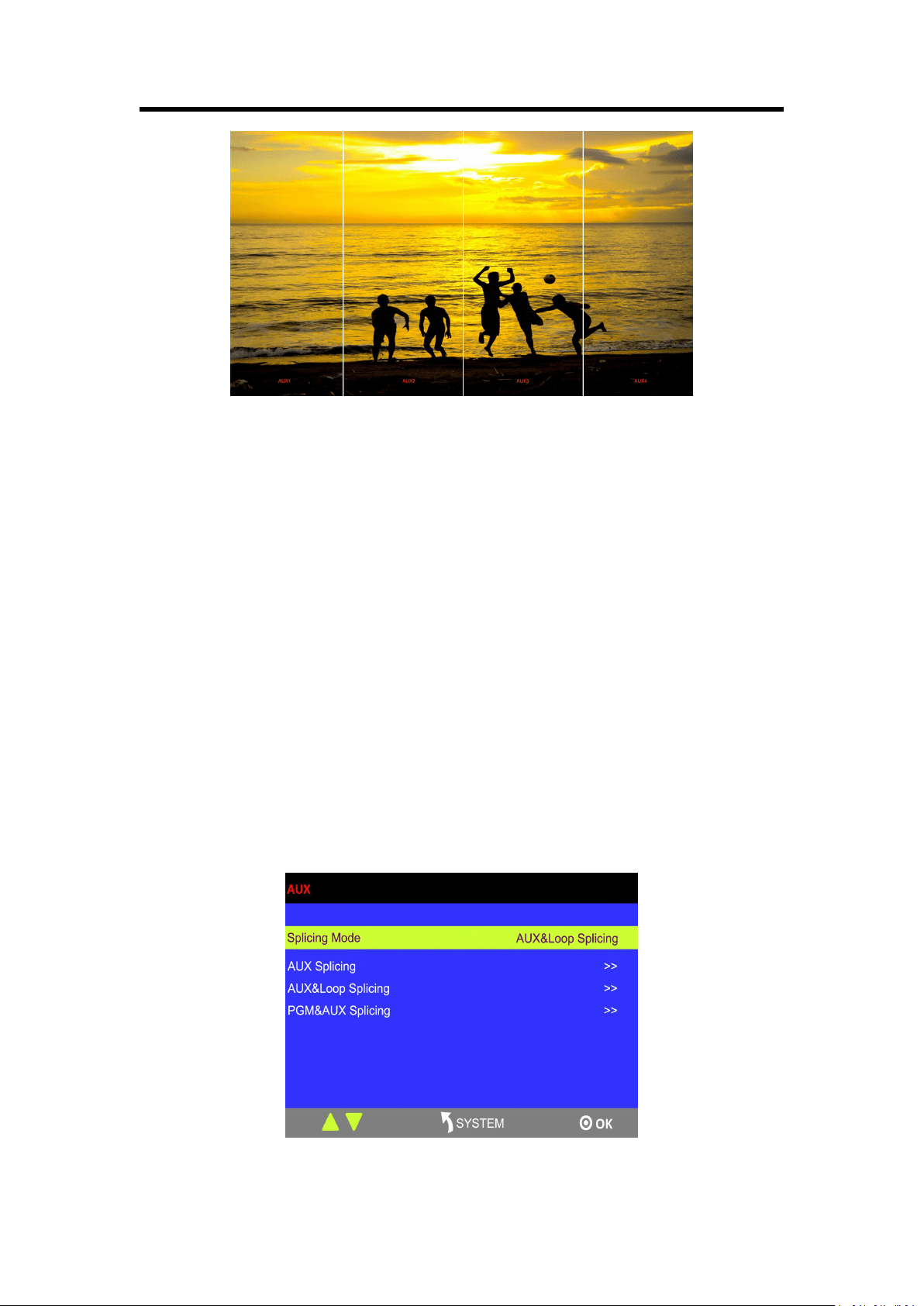
3.7 AUX Mode
Press [AUX] button in PST/PGM Monitor Area, and get into the AUX menu items:
M3 has 3 splicing modes, AUX Splicing, AUX&LOOP Splicing and PGM&AUX Splicing.
Note:
Use TAKE/ CUT button for transition under AUX mode. Using T-Bar will lead to deletion of layers.
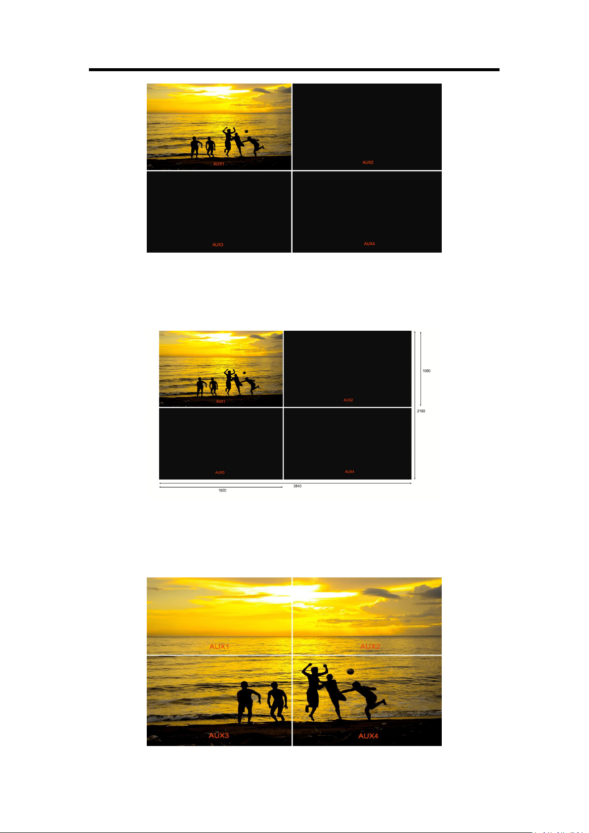
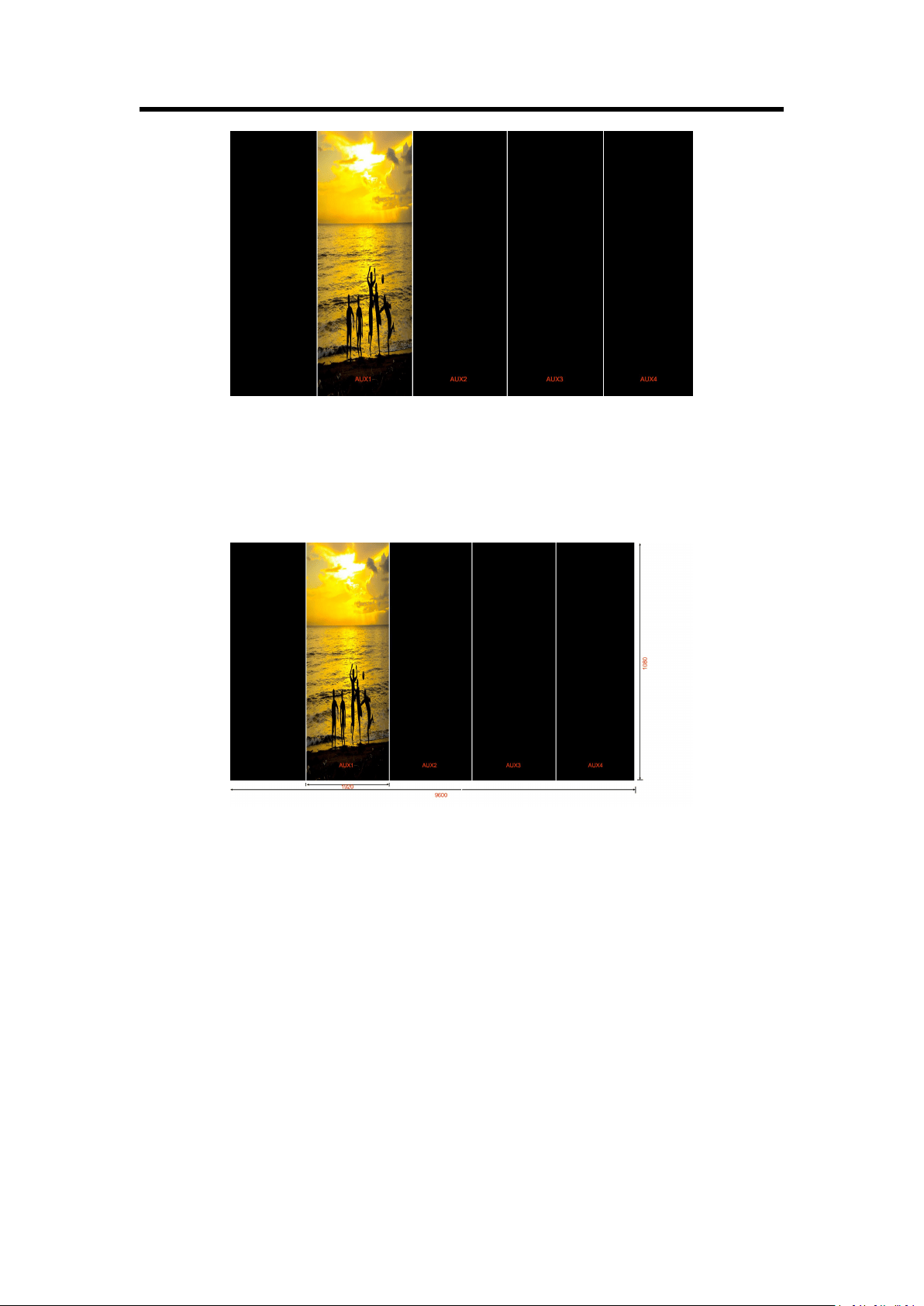
3.7.1 AUX Splicing
1. Turn the rotary knob, and select <AUX Splicing>, press the knob to confirm, and get into the
menu items.
2. Select the splicing mode, <田> and <||||> can be selected.
田 Splicing Mode
(1) Select the signal, for example, select signal 5, as shown below:
Chapter 3: Using Your Product
40
(2) Then, the H Total is 3840, V Total is 2160.
AUX 1: AUX 1 Pos X is 0, AUX 1 Pos Y is 0, AUX 1 H Size is 1920, AUX 1 V Size is 1080.
AUX 2: AUX 2 Pos X is 1920, AUX 2 Pos Y is 0, AUX 2 H Size is 1920, AUX 2 V Size is 1080.
AUX 3: AUX 3 Pos X is 0, AUX 3 Pos Y is 1080, AUX 3 H Size is 1920, AUX 3 V Size is 1080.
AUX 4: AUX 4 Pos X is 1920, AUX 4 Pos Y is 1080, AUX 4 H Size is 1920, AUX 4 V Size is 1080.
User can also customize the size and position of each AUX.
(3) Press [SIZE] button;
According to the parameters from Step 2, set Scale H Size as 3840, [1920 (AUX1/3)+1920
(AUX2/4)=3840], and set Scale V Size as 2160 [1080 (AUX1/3)+1080 (AUX2/4)=2160]. The
image or video will output to the 4 split screens, as shown in the figure below:

Chapter 3: Using Your Product
41
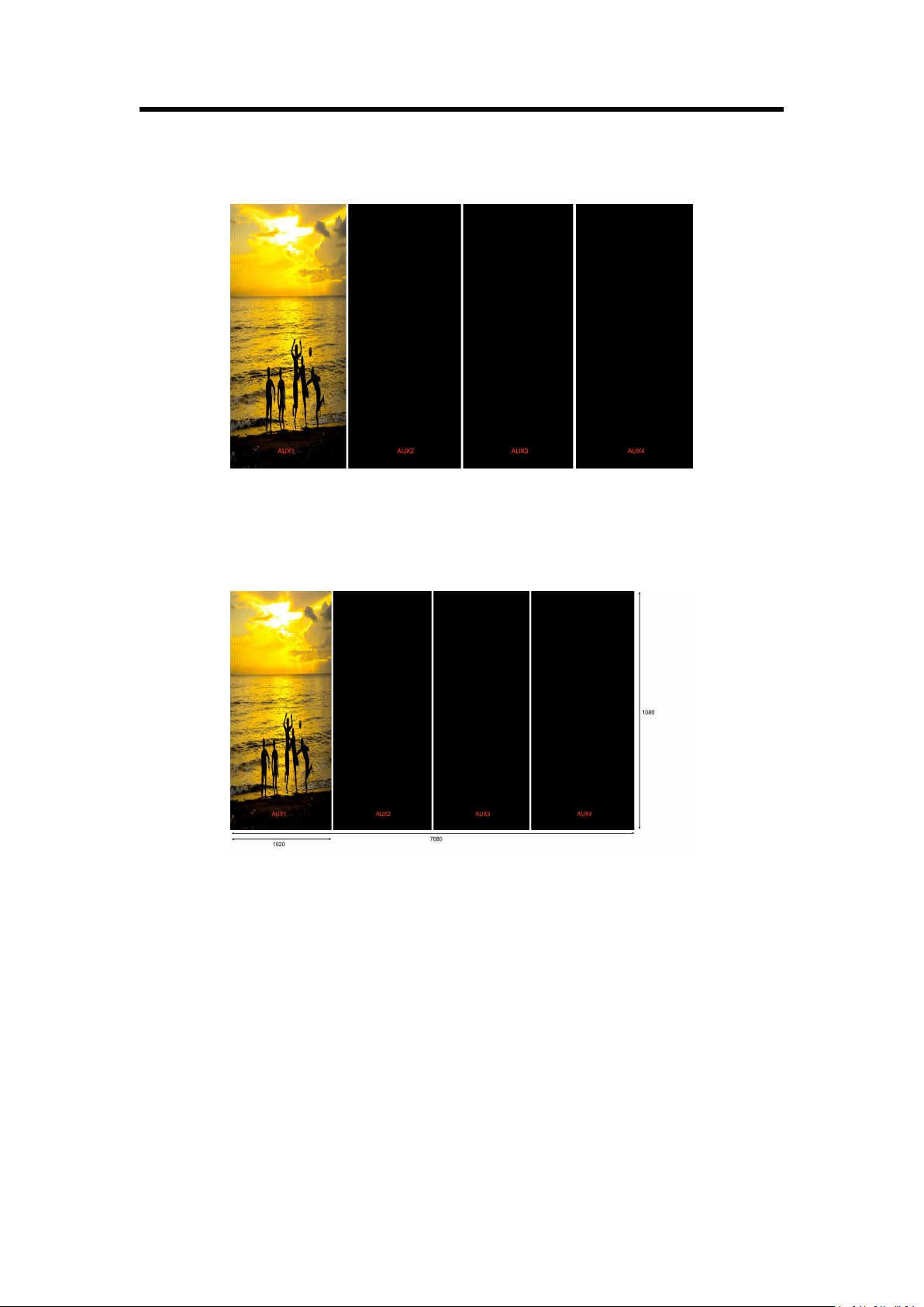
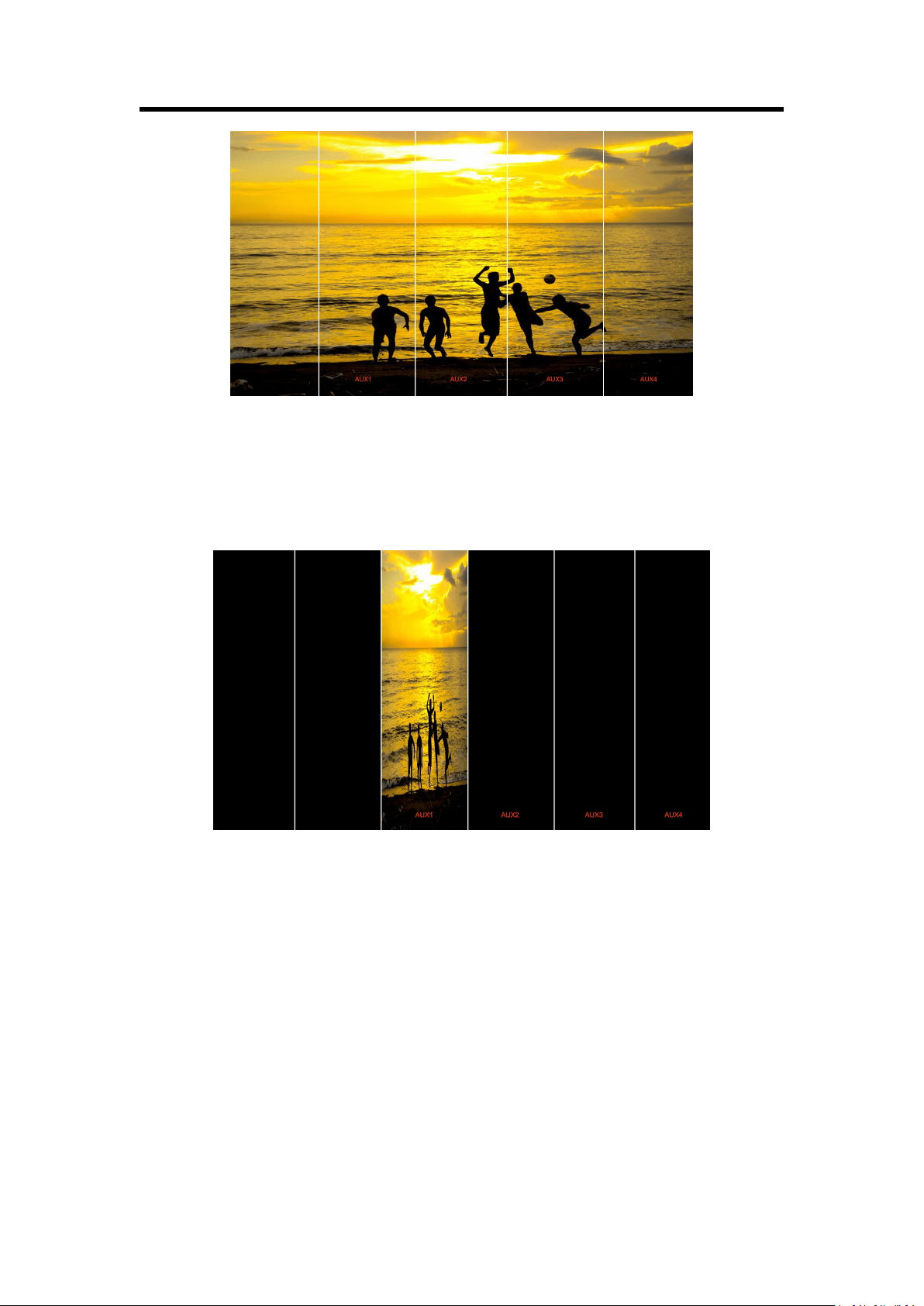
|||| Splicing Mode
(1) Select the signal, for example, select signal 5, as shown below:
(2) Then, the H Total is 7680, V Total is 1080.
AUX 1: AUX 1 Pos X is 0, AUX 1 Pos Y is 0, AUX 1 H Size is 1920, AUX 1 V Size is 1080.
AUX 2: AUX 2 Pos X is 1920, AUX 2 Pos Y is 0, AUX 2 H Size is 1920, AUX 2 V Size is 1080.
AUX 3: AUX 3 Pos X is 3840, AUX 3 Pos Y is 0, AUX 3 H Size is 1920, AUX 3 V Size is 1080.
AUX 4: AUX 4 Pos X is 5760, AUX 4 Pos Y is 0, AUX 4 H Size is 1920, AUX 4 V Size is 1080.
User can also customize the size and position of each AUX.
(3) Press [SIZE] button;
According to the parameters from Step 2, set Scale H Size as 7680, [1920 (AUX1)+1920 (AUX2)
+1920 (AUX3) +1920 (AUX4)=7680]. The image or video will output to the 4 split screens, as
shown in the figure below:
Chapter 3: Using Your Product
42
PIP (only available on M3 e)
PIP is available under AUX Splicing mode on M3 e. (Please refer to M3 e AUX split manual).
Note:
When [Control] button is on, the background layer can be edited; when the light is off, the
sub-layers can be edited. User can set the size and position of sub-layers with [SIZE] button.
3.7.2 AUX&LOOP Splicing
In this mode, the port can display up to 5 images. Select 2K1K multiview and loop splice the
multiview, the views will be displayed on 4K2K or 8K1K screen. The mode has two kinds of loop:
internal loop and external loop. External loop means that the loop is done by actual connection
between one of the PGM port (HDMI) to the one of the HDMI/DVI input ports.
External loop
(1) Press [AUX] button, and get into the menu:
(2) Select 田 or ||||.
田 Splicing

Chapter 3: Using Your Product
43
Select the loop port after actual connection, for example, Port 12 (DVI).
(3) select loop mode, and select 田 or ||||.
(4) Then, the total W is 3840, total H is 2160.
AUX 1: AUX 1 Pos X is 0, AUX 1 Pos Y is 0, AUX 1 H Size is 1920, AUX 1 V Size is 1080.
AUX 2: AUX 2 Pos X is 1920, AUX 2 Pos Y is 0, AUX 2 H Size is 1920, AUX 2 V Size is 1080.
AUX 3: AUX 3 Pos X is 0, AUX 3 Pos Y is 1080, AUX 3 H Size is 1920, AUX 3 V Size is 1080.
AUX 4: AUX 3 Pos X is 1920, AUX 3 Pos Y is 1080, AUX 3 H Size is 1920, AUX 3 V Size is 1080.
User can set the position, height and width of each port.
(5) Press [SIZE] button;
According to the parameters from Step 2, set Scale H Size as 3840, [1920 (AUX1/3)+1920
(AUX2/4)=3840], and set Scale V Size as 2160 [1080 (AUX1/3)+1080 (AUX2/4)=2160]. The
image or video will output to the 4 split screens, as shown in the figure below:
Internal loop:
(1) Press the rotary button and select <AUX&LOOP Splicing>, press the button to confirm.
(2) Press <PGM LOOP> and select <internal loop>.
(3) Select 田 or ||||.
In the internal loop mode, the PST screen on the right only displays PGM views, and switching
between PST and PGM views is not available. Connect PST OUT port to another device to preview.
Press [BK] button, and the signal can be selected.
田 Splicing Mode
(1) Select the signal, for example, select signal 5, as shown below:

Chapter 3: Using Your Product
44
(2) Then, the H Total is 3840, V Total is 2160.
AUX 1: AUX 1 Pos X is 0, AUX 1 Pos Y is 0, AUX 1 H Size is 1920, AUX 1 V Size is 1080.
AUX 2: AUX 2 Pos X is 1920, AUX 2 Pos Y is 0, AUX 2 H Size is 1920, AUX 2 V Size is 1080.
AUX 3: AUX 3 Pos X is 0, AUX 3 Pos Y is 1080, AUX 3 H Size is 1920, AUX 3 V Size is 1080.
AUX 4: AUX 4 Pos X is 1920, AUX 4 Pos Y is 1080, AUX 4 H Size is 1920, AUX 4 V Size is 1080.
User can also customize the size and position of each AUX.
(3) Press [SIZE] button;
According to the parameters from Step 2, set Scale H Size as 3840, [1920 (AUX1/3)+1920
(AUX2/4)=3840], and set Scale V Size as 2160 [1080 (AUX1/3)+1080 (AUX2/4)=2160]. The
image or video will output to the 4 split screens, as shown in the figure below:
Chapter 3: Using Your Product
45
|||| Splicing Mode
(1) Select the signal, for example, select signal 5, as shown below:
(2) Then, the H Total is 7680, V Total is 1080.
AUX 1: AUX 1 Pos X is 0, AUX 1 Pos Y is 0, AUX 1 H Size is 1920, AUX 1 V Size is 1080.
AUX 2: AUX 2 Pos X is 1920, AUX 2 Pos Y is 0, AUX 2 H Size is 1920, AUX 2 V Size is 1080.
AUX 3: AUX 3 Pos X is 3840, AUX 3 Pos Y is 0, AUX 3 H Size is 1920, AUX 3 V Size is 1080.
AUX 4: AUX 4 Pos X is 5760, AUX 4 Pos Y is 0, AUX 4 H Size is 1920, AUX 4 V Size is 1080.
User can also customize the size and position of each AUX.
(3) Press [SIZE] button;
According to the parameters from Step 2, set Scale H Size as 7680, [1920 (AUX1)+1920 (AUX2)
+1920 (AUX3) +1920 (AUX4)=7680]. The image or video will output to the 4 split screens, as
shown in the figure below:
Chapter 3: Using Your Product
46
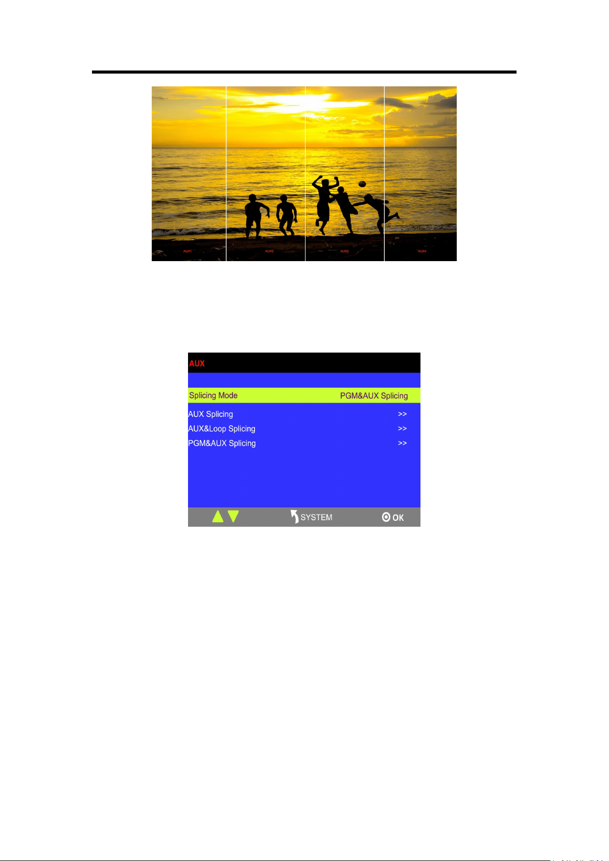
3.7.3 PGM&AUX Splicing
1. Turn the rotary knob, and select <PGM&AUX Splicing>, press the knob to confirm, and get into
the menu items.
2. Select the splicing mode, <|||||> and <||||||> can be selected.
Note:
田 splicing is not available for the version (V1.02).
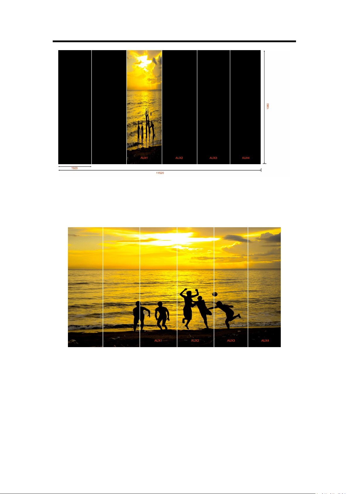
||||| Splicing Mode
(1) Select the signal, for example, select signal 5, as shown below:
Chapter 3: Using Your Product
47
(2) Then, the H Total is 9600, V Total is 1080.
PGM: PGM Pos X is 0, PGM Pos Y is 0, PGM H Size is 1920, PGM V Size is 1080.
AUX 1: AUX 1 Pos X is 1920, AUX 1 Pos Y is 0, AUX 1 H Size is 1920, AUX 1 V Size is 1080.
AUX 2: AUX 2 Pos X is 3840, AUX 2 Pos Y is 0, AUX 2 H Size is 1920, AUX 2 V Size is 1080.
AUX 3: AUX 3 Pos X is 5760, AUX 3 Pos Y is 0, AUX 3 H Size is 1920, AUX 3 V Size is 1080.
AUX 4: AUX 4 Pos X is 7680, AUX 4 Pos Y is 0, AUX 4 H Size is 1920, AUX 4 V Size is 1080.
User can also customize the size and position of each AUX.
(3) Press [SIZE] button;
According to the parameters from Step 2, set Scale H Pos as 0 and Scale H Size as 9600, [1920
(PGM)+1920 (AUX1)+1920 (AUX2)+1920 (AUX3)+1920 (AUX4)=9600], as shown in the figure
below:
Chapter 3: Using Your Product
48
|||||| Splicing Mode
(1) Press [SYSTEM] button, and get into the menu items, select <4K1K> in <Output> option, and
select “ON”.
(2) Select the splicing mode <||||||>.
(3) Select the signal, for example, select signal 5, as shown below:
(4) Then, the H Total is 11520, V Total is 1080.
PGM1: PGM1 Pos X is 0, PGM1 Pos Y is 0, PGM1 H Size is 1920, PGM1 V Size is 1080.
PGM2: PGM2 Pos X is 1920, PGM2 Pos Y is 0, PGM2 H Size is 1920, PGM2 V Size is 1080.
AUX 1: AUX 1 Pos X is 3840, AUX 1 Pos Y is 0, AUX 1 H Size is 1920, AUX 1 V Size is 1080.
AUX 2: AUX 2 Pos X is 5760, AUX 2 Pos Y is 0, AUX 2 H Size is 1920, AUX 2 V Size is 1080.
AUX 3: AUX 3 Pos X is 7680, AUX 3 Pos Y is 0, AUX 3 H Size is 1920, AUX 3 V Size is 1080.
AUX 4: AUX 4 Pos X is 9600, AUX 4 Pos Y is 0, AUX 4 H Size is 1920, AUX 4 V Size is 1080.
Chapter 3: Using Your Product
49
User can also customize the size and position of each AUX.
(5) Press [SIZE] button;
According to the parameters from Step 4, set Scale H Pos as 0 and Scale H Size as 11520,
[1920 (PGM1)+1920 (PGM2)+1920 (AUX1)+1920 (AUX2)+1920 (AUX3)+1920 (AUX4)=11520],
as shown in the figure below:
Chapter 3: Using Your Product
50
3.8 4K1K Mode
1. Press [SYSTEM] button, and get into the menu items, turn the rotary knob, and select
<Output>.
2. Press the knob to confirm. Turn the rotary knob, and select <4K1K>, set “ON”:
3. Press [CONTROL] button, and select the layer.
4. Press any button in the PST area, and select the signal.
5. Press [SIZE] button, and set Scale H Size as 3840. This is the 4K1K mode.
If output the dual graphics to the background input, the operation is as follows:
1. Input the dual graphics signal (HDMI background input).
2. Press [SYSTEM] button, and get into the menu items, turn the rotary knob, and select
<Output>.
3. Press the knob to confirm. Turn the rotary knob, and select <4K1K>, set “ON”:
4. Press [BK] button in the PST area, and select the background signal, then it realizes the 4K1K
mode.
Note:
The background input resolution much be greater than output resolution.
Chapter 3: Using Your Product
51
3.9 Switch Image
1. T-BAR switch: Switch the PST image to PGM with wipe and fade by T-bar.
2. CUT switch: Seamlessly switch the PST image quickly to PGM by pressing [CUT] button.
3. TAKE switch: Switch the PST image to PGM with wipe and fade by pressing [TAKE] button.
4. TRANSITION DURATION: Transition duration settings, the adjustment range is between
0.1~9.9S.
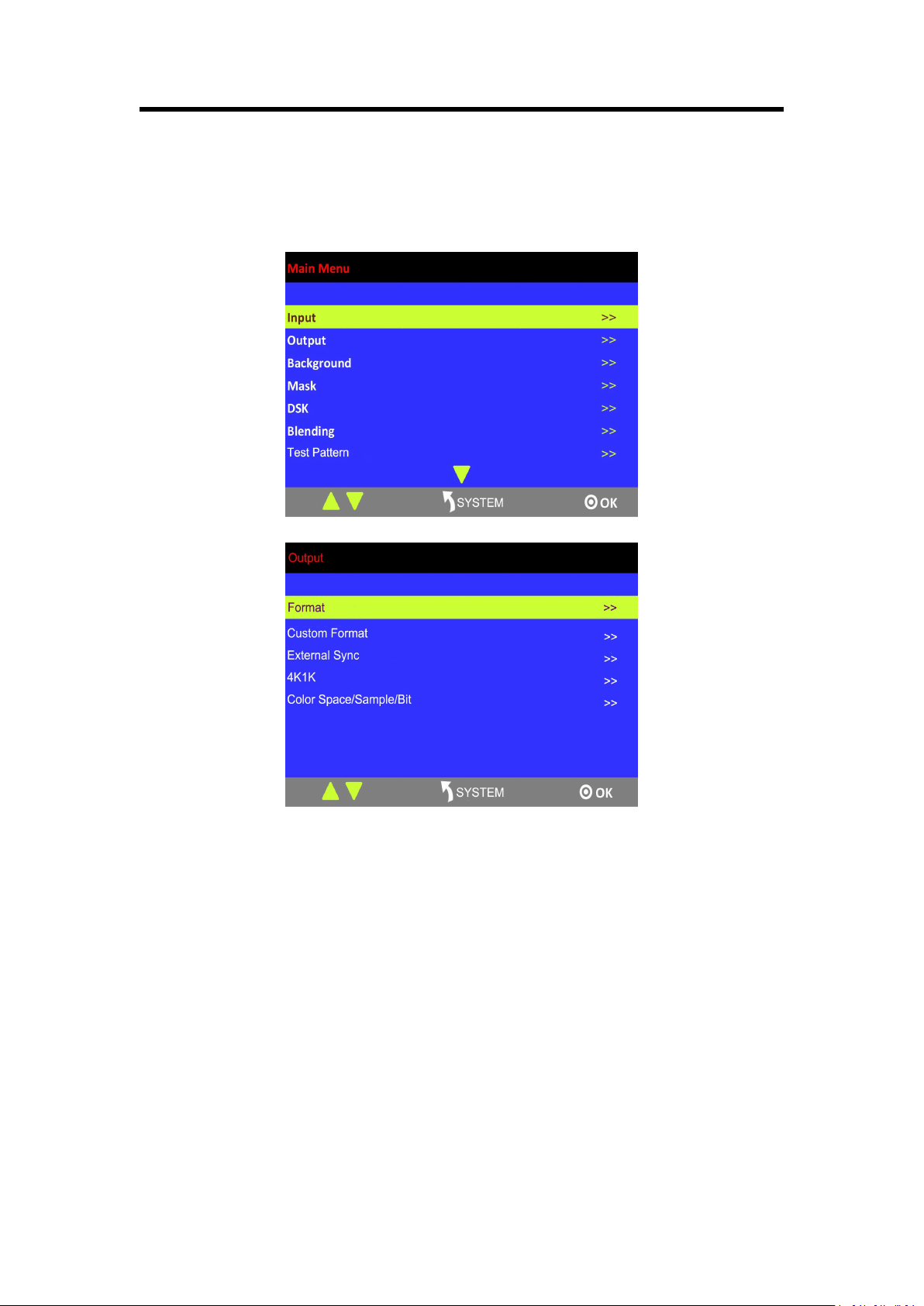
3.10 Set the Output Resolution
3.10.1 Select the Output Resolution
1. Press [SYSTEM] button, and get into the menu items, turn the rotary knob and select
<Output>:
c
2. Press the rotary knob to confirm, and get into the menus .
3. <Format> is the default option, press the rotary to confirm. Turn the rotary knob, select the
output resolution according to actual need.
3.10.2 Custom Output Resolution
1. Press [SYSTEM] button, and get into the menu items, turn the rotary knob and select
<Output>:
Chapter 3: Using Your Product
52
2. Press the rotary knob to confirm, and get into the menus.
3. Turn the rotary knob, and select <Custom Format>, press the rotary knob to confirm.
4. Set H Active, V Active and Freq according to the actual need, then select <Set> and set “Yes”,
press the rotary knob to confirm.
3.11 Using Black Out
Black out description:
Black out with one-key touch.
M3 provides black effect processing for program output and preview output, with cut black effect.
Operation is as below:
Press [BLACK] button, the button light is on, and the program turns black.
The effect is shown as below:
Chapter 3 : Using Your Product
53
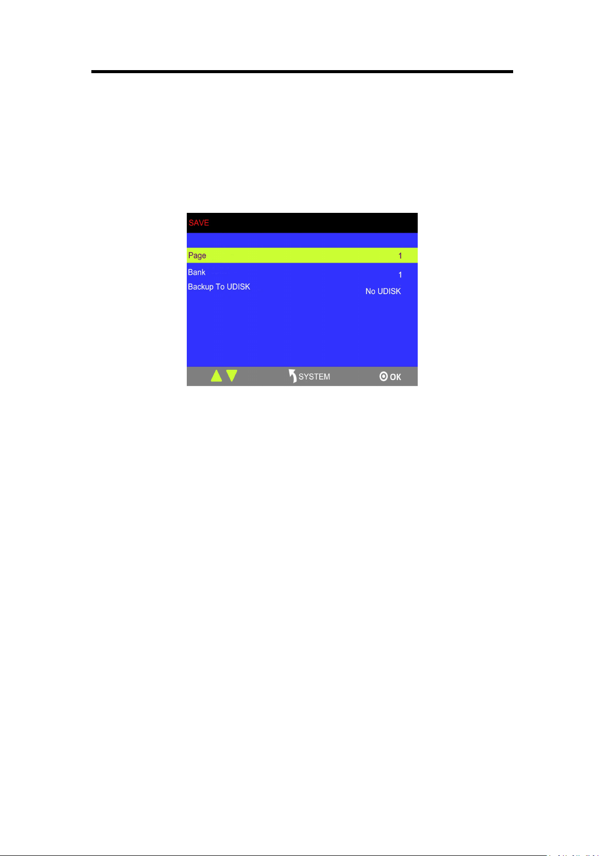
3.12 Saving Views
M3 provides 36 positions for saving or recording parameters. To save current parameters and
settings:
1. Press [SAVE] button in Stored Presets Area, the button [SAVE] and [PAGE] lights are on, and
some of buttons 1~6 are lit and some are flashing. The button lit can be saved and flash will be
overwrite, press the button lit to save.
2. Select PAGE, for example, the button [2] is on, press the button [2].
3. After setting the PAGE, it will jump to Bank option, or example, the button [2] is on, press the
button [2].
4. Press [SAVE] button again, the button light is off, and enable the function.
Chapter 3 : Using Your Product
54
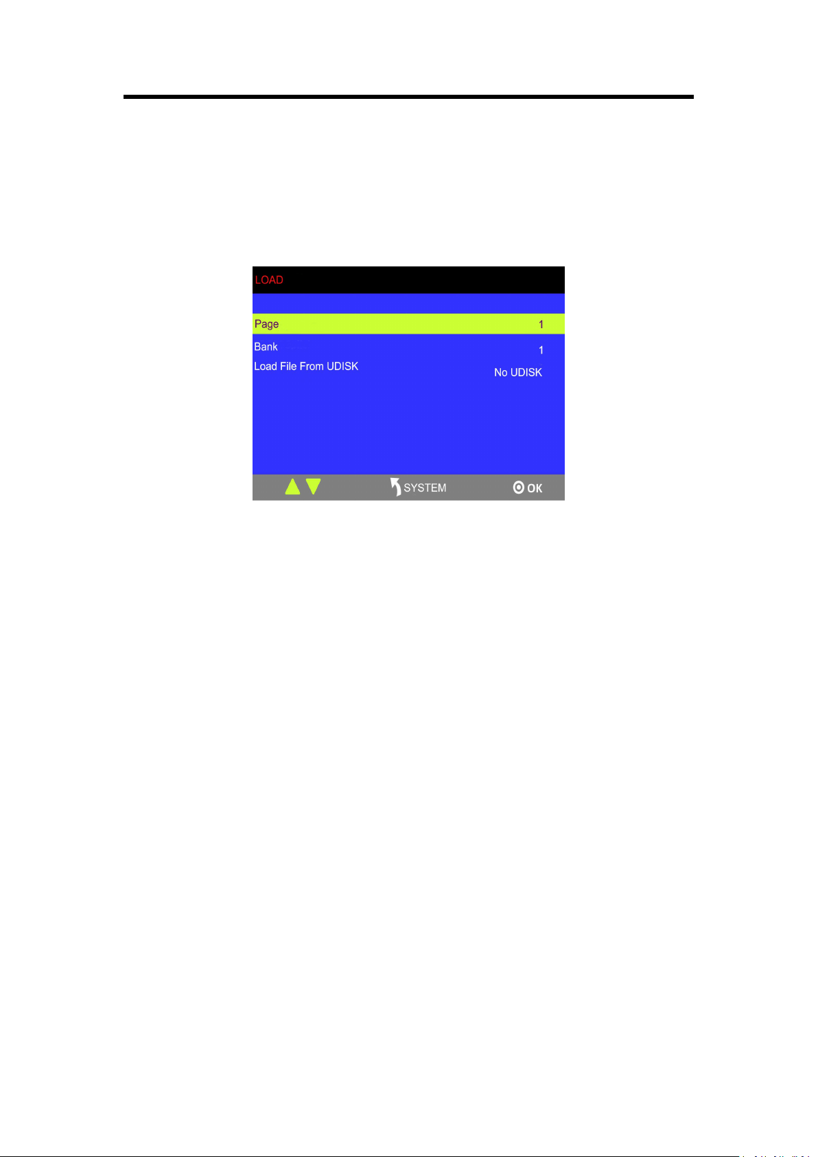
3.13 Recall Saved Settings
M3 provides 36 positions for saving or recording parameters. To recall saved settings:
1. Press [LOAD] button in Stored Presets Area, the button [LOAD] and [PAGE] lights are lit, and
some of buttons 1~6 are lit and some are flashing. The button lit is ready for recall and flash
means just recall, press the button lit to recall.
2. Select PAGE, for example, the button [2] is on, press the button [2].
3. After setting the PAGE, it will jump to Bank option, or example, the button [2] is on, press the
button [2].
4. Press [LOAD] button again, the button light is off, and enable the function.

55
Chapter 4 Ordering Codes
4.1 Product
210-0003-36-1 M3
4.2 Options
4.2.1 Input Options
190-0003-01-0 Quad DVI Input Module
4× DVI
190-0003-02-0 Quad HDMI Input Module
4 × HDMI
190-0003-03-0 Quad VGA Input Module
4 × VGA
190-0003-04-0 Quad SDI Input Module
4 × SDI
190-0003-06-0 8 Way CVBS Input Module
8 × CVBS
190-0003-07-0 Quad USB Input Module
4 × USB (each with loop)
4.2.2 Output Options (AUX)
190-0003-21-0 Quad DVI Output Module
4 × DVI
190-0003-22-0 Quad HDMI Output Module
4 × HDMI
190-0003-24-0 Quad SDI Output Module
4 × SDI
56
Chapter 5 Support
5.1 Questions and Troubleshooting
5.1.1 Customize the MASK, LOGO and STILL
Frequently Asked
Question
Can user customize the MASK, LOGO and STILL for M3?
Troubleshooting
Yes, LOGO image format should be 24 bits BMP format bitmap, total pixels
image size must not exceed 256 x128. And the picture of the sticker format
should be 24 bits BMP format bitmap, total pixels image size must not exceed
128 x128. Make the MASK, LOGO and STILL and copy them to the USB
Disk.
5.1.2 Add the Layer
Frequently Asked
Question
How many layers can be added for M3?
Troubleshooting
Including 4 layers and 1 background in video input, as well as the LOGO,
STILL and OSD, totally 8 layers. The OSD supports 200 pieces of subtitles
and paging function.
5.1.3 Input and Output Option Module Type
Frequently Asked
Question
What kinds of input and output module does M3 support?
Troubleshooting
Same with VENUS X3.
Supported input modules: DVI, VGA, SDI, HDMI, USB and CVBS.
Supported AUX output modules: DVI, HDMI, SDI.
5.1.4 Blending and MASK cannot open synchronously
Frequently Asked
Question
Blending and MASK cannot open synchronously if enable the DSK function.
Troubleshooting
User can only enable one function among DSK, Blending and MASK.
Chapter 5: Support
57
5.2 Contact Us
58
Chapter 6 Appendix
6.1 Specification
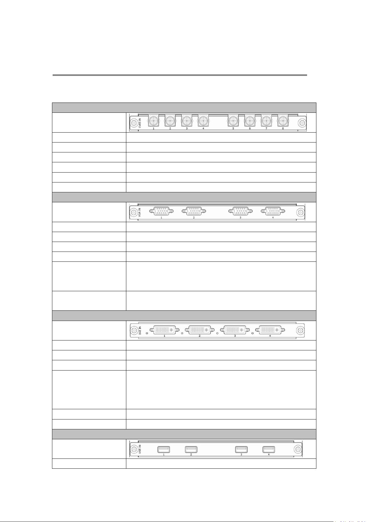
CVBS Input Module
Interface Appearance
Board Size
216(L)×20(W)(mm)
Number of Inputs
8
Connector
Standard BNC Socket
Supported Standards
PAL I NTSC I SECAM
Signal Level
1Vpp±3db (0.7V Video+0.3v Sync ) 75 ohm
Multiplex
480i I 576i
VGA Input Module
Interface Appearance
Board Size
216(L)×20(W)(mm)
Number of Inputs
4
Connector
Standard DB15 Socket
Supported Standard
VGA-UXGA
Signal Level
R、G、B、Hsync、Vsync:0 to1Vpp±3dB (0.7V Video+0.3v Sync )
75 ohm
black level: 300mV Sync-tip: 0V
Supported Resolution
VGA-UXGA (800×600@60 I 1024×768@60 I
1280×1024@60 I 1440×900@60 I 1600×1200@60)
DVI Input Module
Interface Appearance
Board Size
216(L)×20(W)(mm)
Number of Inputs
4
Connector
Standard DVI-I socket
Supported Resolution
SMPTE: 625/25/50 PAL, 525/29.97/59.94 NTSC,
1080P50/59.94/60 I 1080i50/59.94/60 I 720p50/59.94/60
VESA: 800×600@60 I 1024×768@60 I 1280×768@60 I
1280×1024@60 I 1600×1200@60 I 1920×1080@60
Signal Level
TMDS pwl, single pixel input,165MHz bandwidth
Format Standard
HDMI 1.3
USB Input Module
Interface Appearance
Board Size
216(L)×20(W)(mm)
59
Number of Inputs
4
Connector
Standard USB port
Supported Standard
Support general Image and video formats
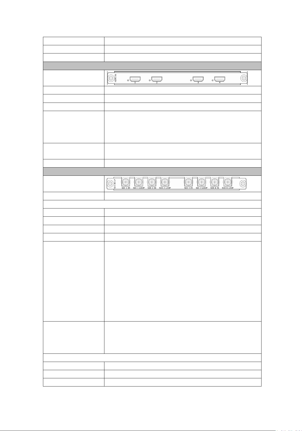
HDMI Input Module
Interface Appearance
Board Size
216(L)×20(W)(mm)
Number of Inputs
4
Connector
HDMI standard type A interface
Supported Resolution
SMPTE: 625/25/50 PAL, 525/29.97/59.94 NTSC,
1080P50/59.94/60 | 1080i50/59.94/60 | 720p50/59.94/60
VESA: 800×600@60 | 1024×768@60 | 1280×768@60 |
1280×1024@60 | 1600×1200@60 | 1920×1080@60
Embedded Audio
Channels
Choose one from the two inputs
Format Standard
HDMI 1.3
3G-SDI Input Module
Interface Appearance
Board Size
216(L)×20(W)(mm)
SDI Input
Number of Inputs
4
Connector
BNC
Data Rate
2.97Gb/s, 2.97/1.001Gb/s, 1.485Gb/s, 1.485/1.001Gb/s and 270Mb/s
Supported Standard
SMPTE 425M - 3G Level A Format
Supported Resolution
SMPTE 425M (3G Level A) 4:2:2: 1920×1080/60 (1:1),
1920×1080/50 (1:1).
SMPTE 274M (HD): 1920×1080I/60 (2:1) or
1920×1080/30 (PsF) I 1920×1080I/50 (2:1) or
1920×1080/25 (PsF) I 1920×1080/30 (1:1),
1920×1080/25 (1:1) I 1920×1080/24 (1:1),
1920×1080/24 (PsF)
SMPTE 125M (SD): 1440×487/60 (2:1)
SMPTE ITU-R BT.656 (SD): 1440×576/50 (2:1) Or dual link
progressive, 625-line generic.
Balance
Belden 1694A cable:
150m at 2.97Gb/s
250m at 1.485Gb/s
480m at 270Mb/s
SDI Loop Out
Number of Loop Out
4
Connector
BNC
Data Rate
2.97Gb/s, 2.97/1.001Gb/s, 1.485Gb/s, 1.485/1.001Gb/s and 270Mb/s
60
Supported Standard
SMPTE 425M - 3G Level A Format
Supported Resolution
SMPTE 425M (3G Level A) 4:2:2: 1920×1080/60 (1:1),
1920×1080/50 (1:1).
SMPTE 274M (HD): 1920×1080I/60 (2:1) or
1920×1080/30 (PsF) I 1920×1080I/50 (2:1) or
1920×1080/25 (PsF) I 1920×1080/30 (1:1),
1920×1080/25 (1:1) I 1920×1080/24 (1:1),
1920×1080/24 (PsF)
SMPTE 125M (SD): 1440×487/60 (2:1)
SMPTE ITU-R BT.656 (SD): 1440×576/50 (2:1) Or dual link
progressive, 625-line generic.
Balance
Belden 1694A cable:
150m at 2.97Gb/s
250m at 1.485Gb/s
480m at 270Mb/s
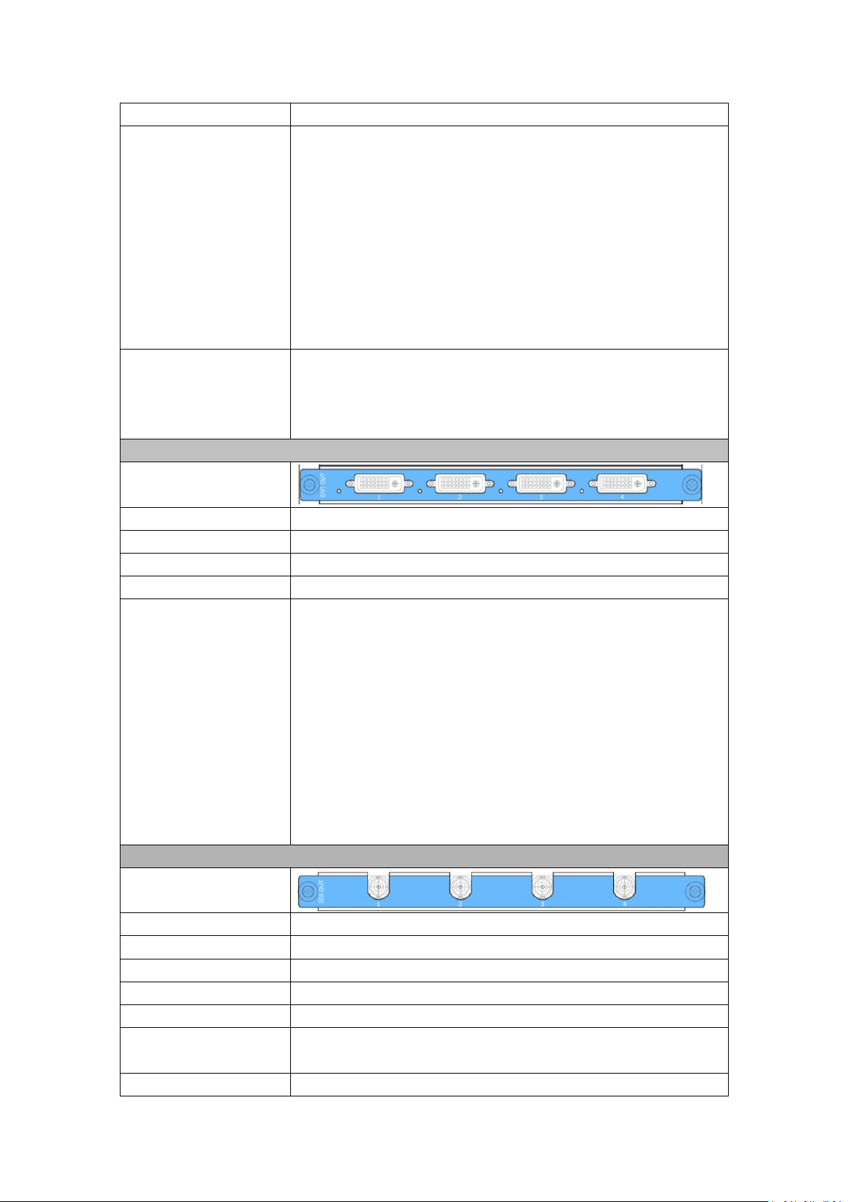
DVI Output Module
Interface Appearance
Board Size
216(L)×20(W)(mm)
Number of Outputs
4
Connector
Standard DVI-I Socket
Signal Level
TMDS pw, 165MHz bandwidth
Supported Resolution
SMPTE: SMPTE: 625/25/50 PAL, 525/29.97/59.94 NTSC,
1080P50/59.94/60 I 1080i50/59.94/60 I 720p50/59.94/60
VESA:
720×480@50i I 720×480@60i I 1024×768@60 I 1024×768@75 I
I 1280×800@60 I 1280×1024@60 I 1280×1024@75 I
1280×1024@85 I 1360×768@60 I 1366×768@60 I 1400×1050@60 I
1440×900@60 I 1600×1200@60 I 1680×1050@60 I 1920×1080@50i
2048×1152@60 I 2560×816@60
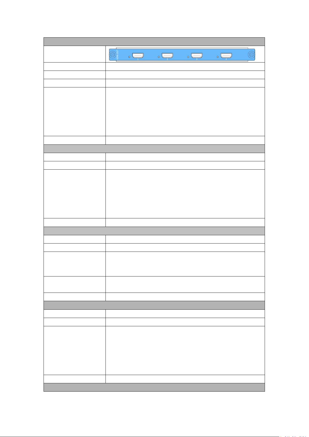
SDI Output Module
Interface Appearance
Board Size
216(L)×20(W)
(
mm
)
Number of outputs
4
Connector
BNC interface
Signal level
800mV±10%
Supported Standard
SMPTE 425M - 3G Level A Format
Supported Resolution
SMPTE: 480i
I
576i, 720p/50/59.94/60
I
1080i/50/59.94/60
I
1080p/50/59.94/60
Equalization
Belden 1694A 100m HD 1.485G, 300m SD 270Mbps
61
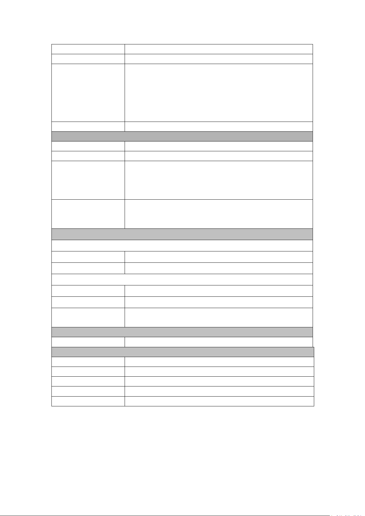
HDMI Output Module
Interface Appearance
Board Size
216(L)×20(W)(mm)
Number of outputs
4
Connector
HDMI standard type A interface
Supported Resolution
SMPTE: 625/25 PAL, 525/29.97 NTSC, 625/50p PAL,
525/59.94p NTSC,
720p50/59.94/60
I
1080i50/59.94/60
I
1080P50/59.94/60
VESA: 800×600@60
I
1024×768@60
I
1280×768@60
I
1280×1024@60
I
1600×1200@60
I
1920×1080@60
I
1920×1080@50
Format Standard
HDMI 1.3
HDMI PGM Output
Number of Outputs
2
Connector
HDMI standard type A interface
Supported Resolution
SMPTE: 625/25 PAL, 525/29.97 NTSC, 625/50p PAL,
525/59.94p NTSC,
720p50/59.94/60 I 1080i50/59.94/60 I 1080P50/59.94/60
VESA: 800×600@60 I 1024×768@60 I 1280×768@60 I
1280×1024@60 I 1600×1200@60 I 1920×1080@60 I
1920×1080@50
Format Standard
HDMI 1.3
HDMI Background Input
Interface Appearance
2
Connector
HDMI standard type A interface
Supported Resolution
SMPTE: 1080P50/59.94/60 I 720p50/59.94/60
VESA: 800×600@60 I 1024×768@60 I 1280×768@60 I
1280×1024@60 I 1600×1200@60 I 1920×1080@60
Embedded Audio
Channels
Choose one from the two inputs
Format Standard
HDMI 1.3
HDMI PST Output
Number of outputs
1
Connector
HDMI standard type A interface
Supported Resolution
SMPTE: 625/25 PAL, 525/29.97 NTSC, 625/50p PAL,
525/59.94p NTSC,
720p50/59.94/60 I 1080i50/59.94/60 I 1080P50/59.94/60
VESA: 800×600@60 I 1024×768@60 I 1280×768@60 I
1280×1024@60 I 1600×1200@60 I 1920×1080@60 I
1920×1080@50
Format Standard
HDMI 1.3
HDMI PVW Output
62
Number of outputs
1
Connector
HDMI standard type A interface
Supported Resolution
SMPTE: 625/25 PAL, 525/29.97 NTSC, 625/50p PAL,
525/59.94p NTSC,
720p50/59.94/60 I 1080i50/59.94/60 I 1080P50/59.94/60
VESA: 800×600@60 I 1024×768@60 I 1280×768@60 I
1280×1024@60 I 1600×1200@60 I 1920×1080@60 I
1920×1080@50
Format Standard
HDMI 1.3
VGA PVW Output
Number of outputs
1
Connector
Standard DB15 Socket
Supported Resolution
VESA: 800×600@60 I 1024×768@60 I 1024×768@75 I
1280×768@60 I 1280×1024@60 I 1440×900@60 I 1400×1200@60 I
1600×1200@60 I 1920×1080@60 I 1920×1200@60 I
2048×1152@60
Signal Level
R, G, B, Hsync、Vsync:0 to1Vpp±3dB (0.7V Video+0.3v Sync ) 75
ohm
black level: 300mV Sync-tip: 0V
Genlock Interface
Genlock Input
Number of Inputs
1
Connector
BNC
Genlock Loop
Number of Inputs
1
Connector
BNC
Supported Resolution
480i I 576i I 1080i59.94 I 1080i50 I 720p50 I 720p59.94 I 1080p50 I
1080p59.94 I 1080p60 I 1080psf23.98 I 1080psf24
Function
Switch
Support any two inputs fade in fade out
Extras
Communication
RS232 USB TCP/IP
Power Supply
100-240V IEC-3
Working Environment
0°C~45°C
Stored Environment
10% to 90%
Product Warranty
3 years parts and labor warranty
63
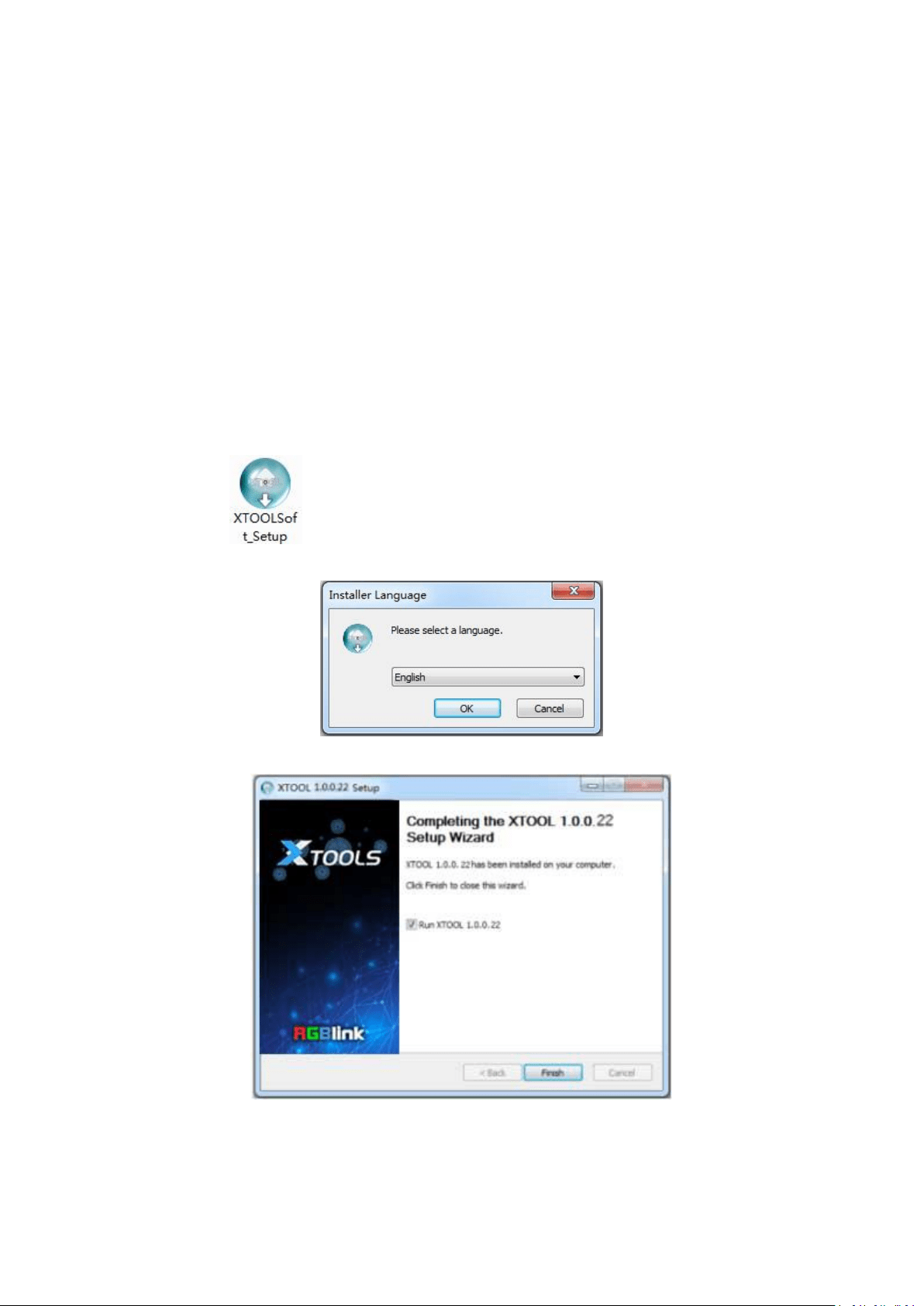
6.2 Software Upgrade
Use XTOOL to upgrade the software.
6.2.1 Installing XTOOL
Environment Requirements:
Processor: 1 GHz or above 32 bit or 64 bit processor
Memory: 2 GB or more
Graphics: Support DirectX 9 128M or above (open AERO effect)
Hard disk space: Above 16G (primary partitions, NTFS format)
Monitor: Resolution must be 1280 x720 pixel or above (it can not display normally if the
resolution is lower than 1280 x720)
Operating system: Windows 7 or above (full version, not Ghost version or compact version)
Double click
icon, it will pop-up the installer language box, select the language, for
example, select “English”, and click “OK” to confirm.
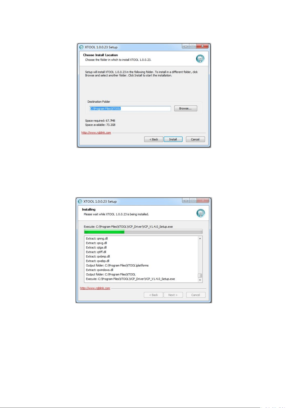
Click “Next” to install:
64
Select “Browse...” to select the XTOOL software installation path:
Note:
User should get the rights in “Roles Management” when installing the software to disk C if the
system is Windows 7 or above.
Click “Install”:
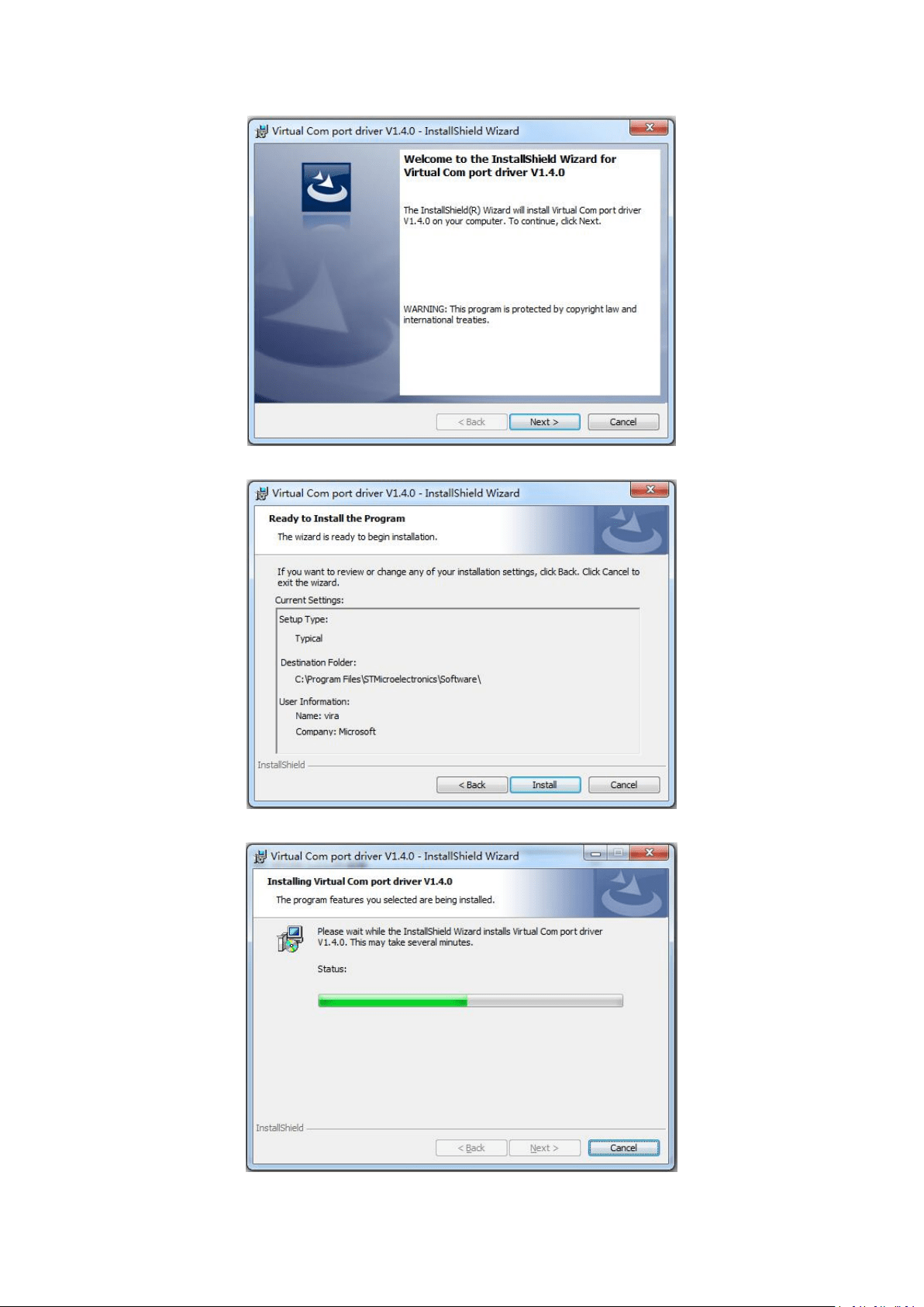
During installation, it will pop up the window of Install Shield Wizard for Virtual Com port:
65
(1) If user install the XTOOL software for the first time, click “Next”:
Then click “Install", as shown in the figure below:
66
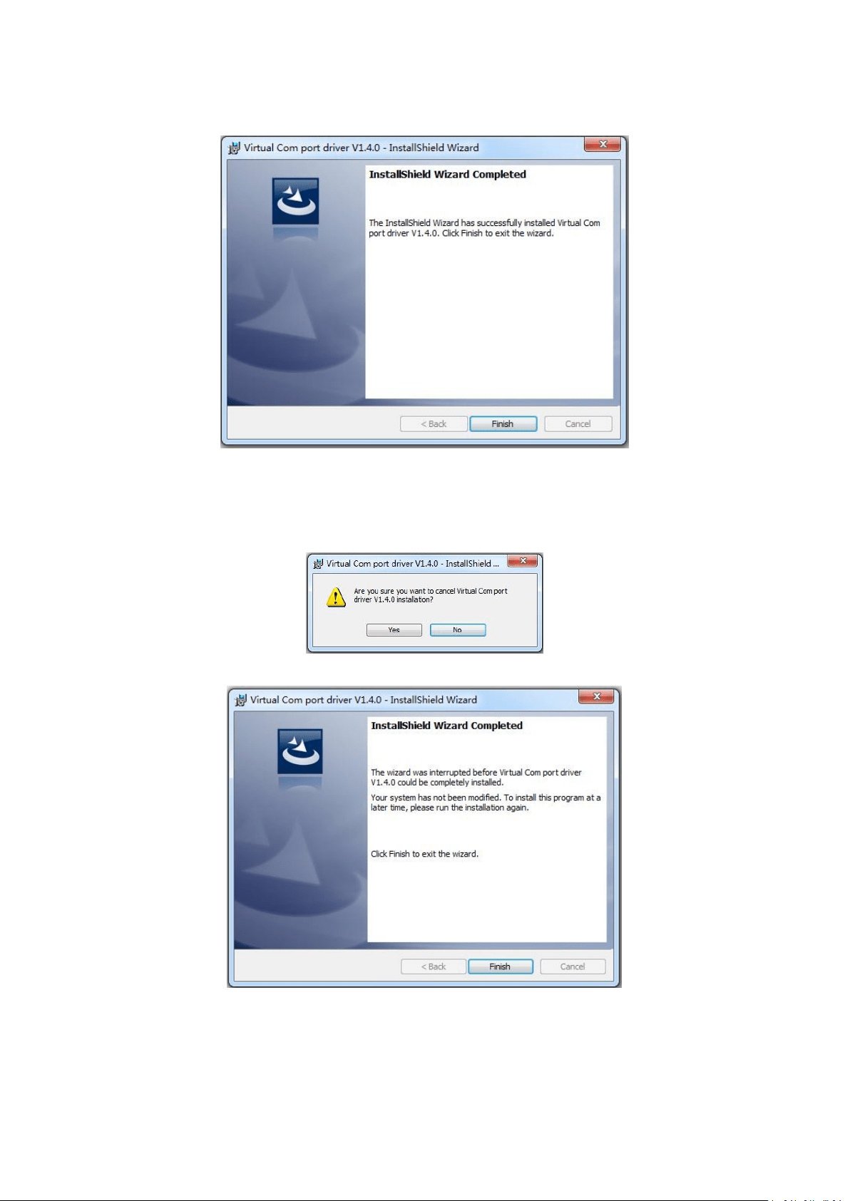
Click “Finish” and complete the installation, as shown in the figure below:
Then it will pop up the window of installation wizard for device driver, click “Next” to
complete the installation.
(2) If user have installed the XTOOL software before, click “Cancel”, and it will pop up the window
as below:
Click “Yes” to cancel installation.
Click “Finish” to exit installation.
Then it will pop up the window of installation wizard for device driver, click “Cancel” to exit
the installation.
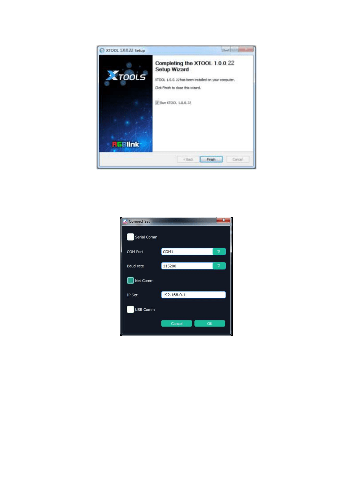
Click “Finish” and is ready to run the XTOOL software:
67
6.2.2 Upgrading the device
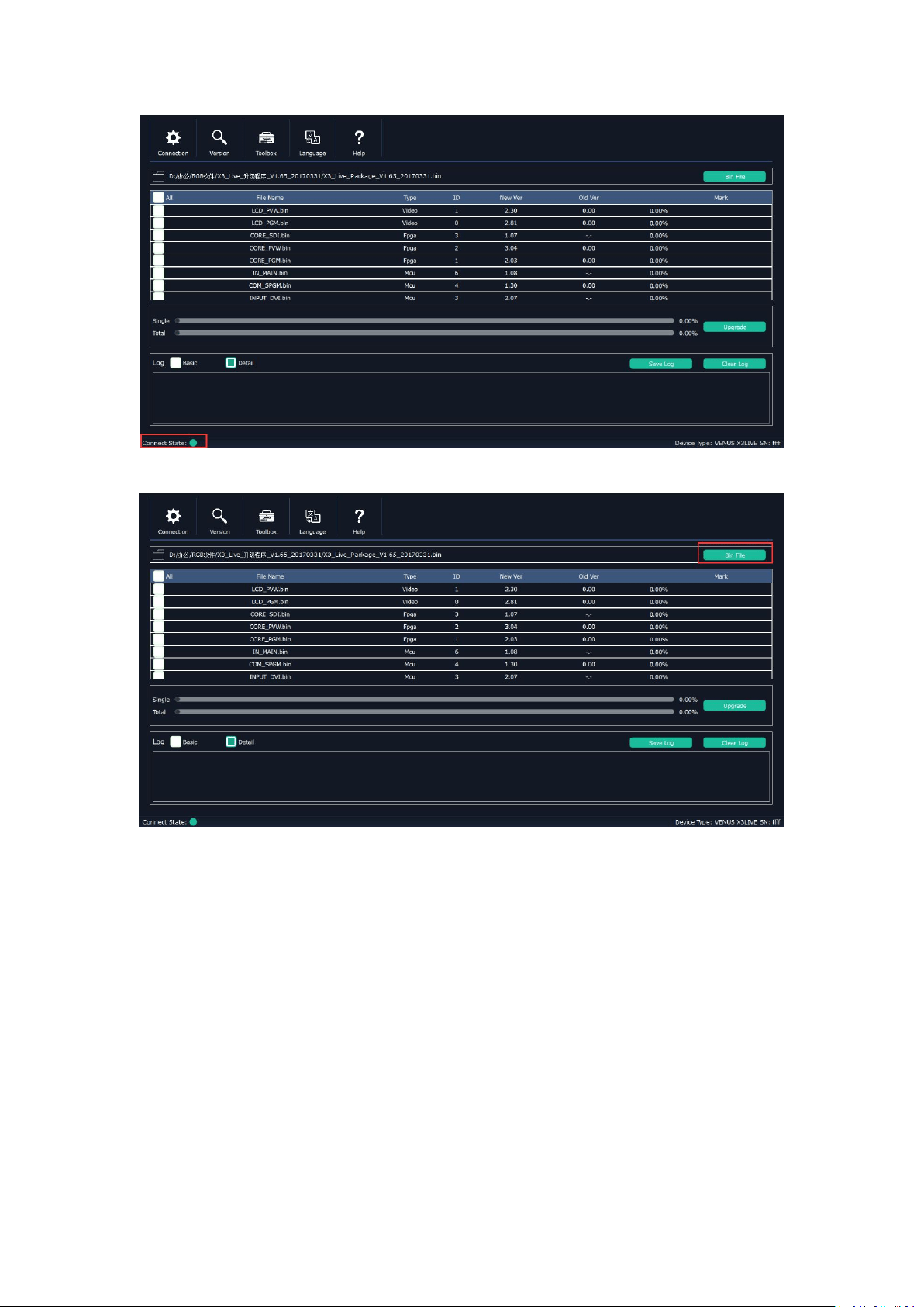
(1) Click “Connection”, and window pops up as follows:
Serial Comm, Net Comm and USB Comm can be selected. Click “OK” to confirm. When connected,
the status indicator light turns green, see the picture below:
68
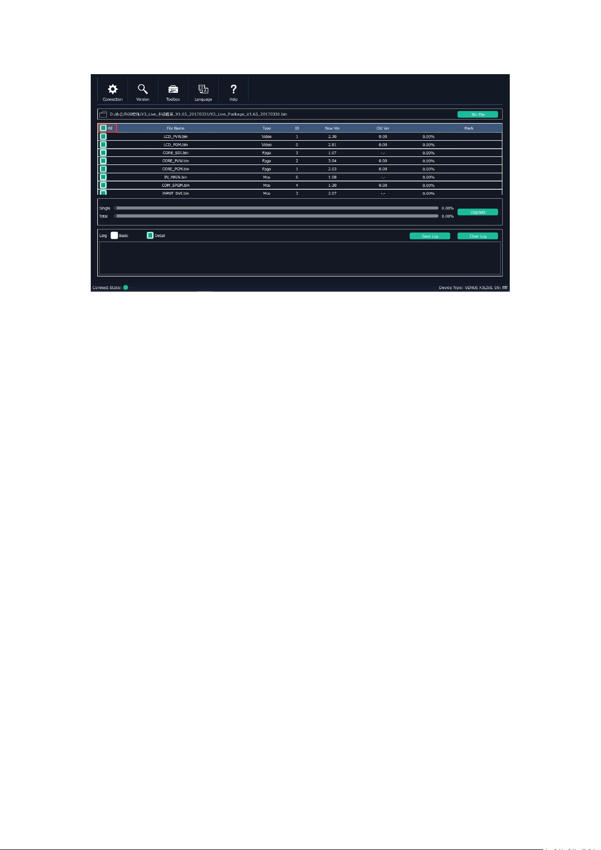
(2) Click bin file on the top right corner.
(3)
Upload the target upgrade package, and tick “ALL”. Items that need upgrade will turn green.
69
(4) Click “Upgrade”.
*User should reboot the device after upgrade.
70
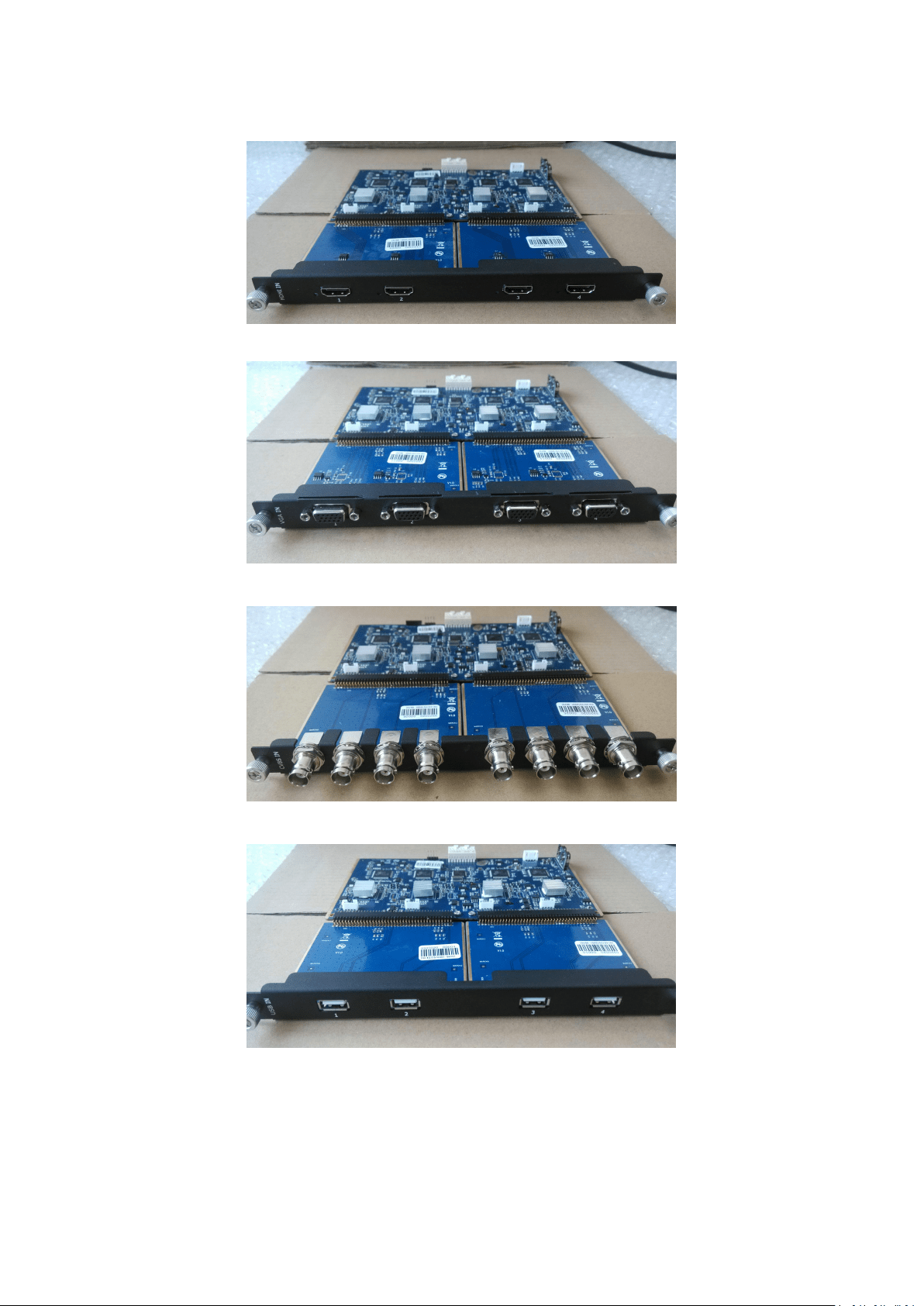
6.3 Module Installation
M3 and X3 support replaceable input and output optional modules, user can install or replace the
optional module according to actual need. Take X3 for example, the specific installation steps are
as follows:
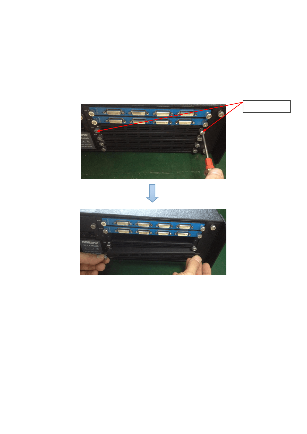
Install the Optional Module
1. Unscrew the 2 captive screws in input modules block, and pull out the input module
block, as shown in figure:
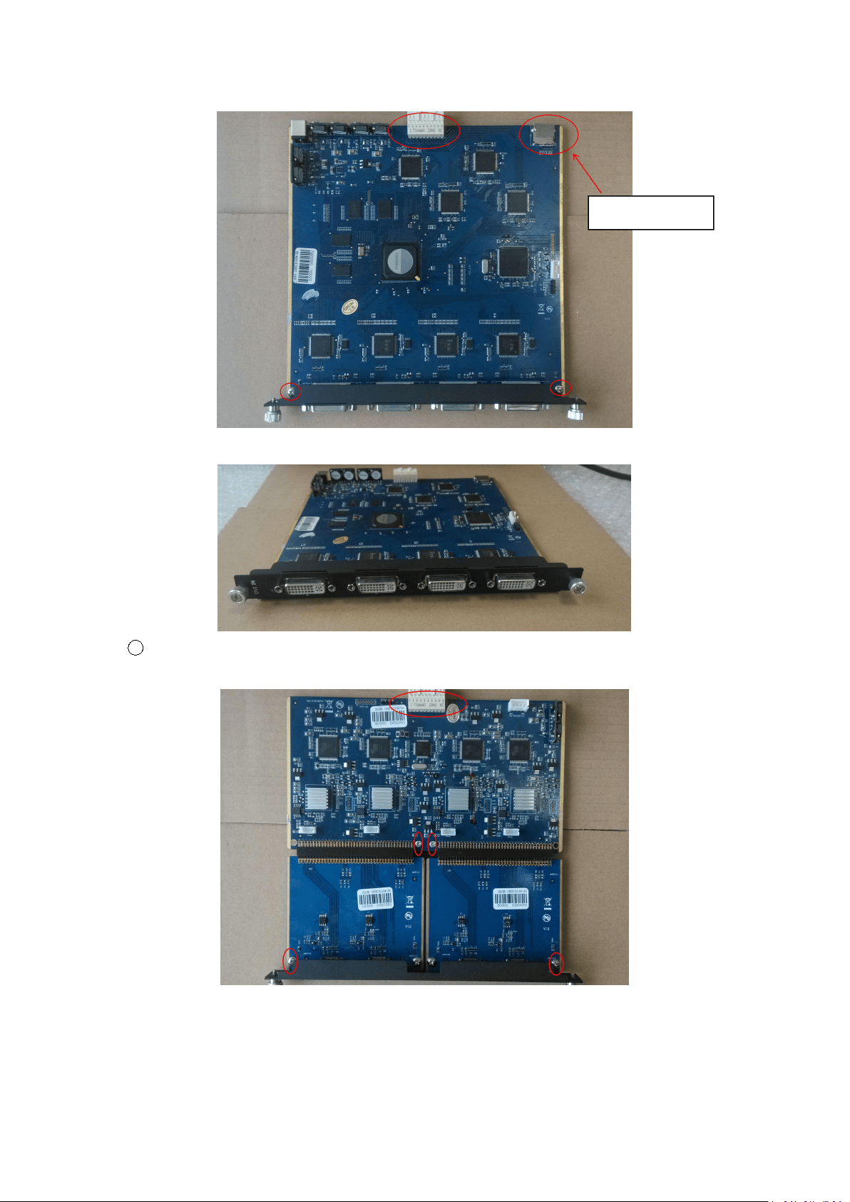
2. Install the input module:
For the whole PCB input module with DVI or HDMI interface, fix the input module on the plate
with 2 M3*4 flat screws, also need to install the 2G Micro SD card.
Captive Screw
71
DVI input module:
1
For the joined PCB input module with CVBS, HDMI, VGA, USB or SDI interface, fix the input
module on the plate with 2 M3*4 flat screws and 2 M3*4 round head screws.
Micro SD card
72
HDMI input module:
VGA input module:
CVBS input module:
USB input module:
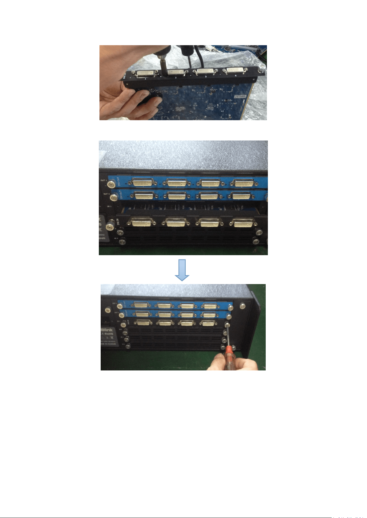
3. Fix the input module block with fixed screws, as shown in figure:
73
4. Press the input modules into the device along the slide rail, and screw the captive
screws, as shown in figure:
Note:
The install steps of output module installation and input/output module replacement are the
same as above.

Chapter 6: Appendix
74
6.4 Terms & Definitions
The following terms and definitions are used throughout this guide.
“ASCII”: American Standard for Information Interchange. The standard code consisting of
7-bit coded characters (8 bits including parity check) used to exchange information
between data processing systems, data communication systems, and associated equipment.
The ASCII set contains control characters and graphic characters.
“Aspect ratio”: The relationship of the horizontal dimension to the vertical dimension of an
image. In viewing screens, standard TV is 4:3, or 1.33:1; HDTV is 16:9, or 1.78:1. Sometimes
the “:1” is implicit, making TV = 1.33 and HDTV = 1.78.
“AV”: Audio visual, or audio video.
A “Background” is an unscaled source, typically originating from a computer. A background
source appears at the system’s lowest priority — visually in back of all other sources.
“Baudrate”: Named of J.M.E. Baudot, the inventor of the Baudot telegraph code. The
number of the electrical oscillations per second, called baud rate. Related to, but not the
same as, transfer rate in bits per second (bps).
“Blackburst”: The video waveform without the video elements. It includes the vertical sync,
horizontal sync, and the chroma burst information. Blackburst is used to synchronize video
equipment to align the video output. One signal is normally used to set up an entire video
system or facility. Sometimes it is called House sync.
“BNC”: Bayonet Neill-Concelman. A cable connector used extensively in television and
named for its inventors. A cylindrical bayonet connector that operates with a twist-locking
motion. To make the connection, align the two curved grooves in the collar of the male
connector with the two projections on the outside of the female collar, press, and twist.
This allows the connector to lock into place without tools.
“Brightness”: Usually refers to the amount or intensity of video light produced on a screen
without regard to color. Sometimes called “black level.
“CAT 5”: Category 5. Describes the network cabling standard that consists of four
unshielded twisted pairs of copper wire terminated by RJ-45 connectors. CAT 5 cabling
supports data rates up to 100 Mbps. CAT 5 is based on the EIA/TIA 568 Commercial
Building Telecommunications Wiring Standard.
“Color bars”: A standard test pattern of several basic colors (white, yellow, cyan, green,
magenta, red, blue, and black) as a reference for system alignment and testing. In NTSC
video, the most commonly used color bars are the SMPTE standard color bars. In PAL video,
the most commonly used color bars are eight full field bars. In the computer, the most
commonly used color bars are two rows of reversed color bars.
“Color burst”: In color TV systems, a burst of subcarrier frequency located on the back
porch of the composite video signal. This serves as a color synchronizing signal to establish
a frequency and phase reference for the chroma signal. Color burst is 3.58 MHz for NTSC
and 4.43 MHz for PAL.
“Color temperature”: The color quality, expressed in degrees Kelvin(K), of a light source.
The higher the color temperature, the bluer the light. The lower the temperature, the
redder the light. Benchmark color temperature for the A/V industry include 5000°K, 6500°K,
and 9000°K.

Chapter 6: Appendix
75
“Contrast ratio”: The radio of the high light output level divided by the low light output level.
In theory, the contrast radio of the television system should be at least 100:1, if not 300:1.
In reality, there are several limitations. In the CRT, light from adjacent elements
contaminate the area of each element. Room ambient light will contaminate the light
emitted from the CRT. Well-controlled viewing conditions should yield a practical contrast
ratio of 30:1 to 50:1.
“DVI”: Digital Visual Interface. The digital video connectivity standard that was developed by
DDWG (Digital Display Work Group). This connection standard offers two different
connectors: one with 24 pins that handles digital video signals only, and one with 29 pins
that handles both digital and analog video.
“EDID”: Extended Display Identification Data – EDID is a data structure used to communicate
video display information, including native resolution and vertical interval refresh rate
requirements, to a source device. The source device will then output the optimal video
format for the display based on the provided EDID data, ensuring proper video image
quality. This communication takes place over the DDC – Display Data Channel.
“Ethernet”: A Local Area Network (LAN) standard officially known as IEEE 802.3. Ethernet
and other LAN technologies are used for interconnecting computers, printers, workstations,
terminals, servers, etc. within the same building or campus. Ethernet operates over twisted
pair and over coaxial cable at speeds starting at 10Mbps. For LAN interconnectivity,
Ethernet is physical link and data link protocol reflecting the two lowest layers of the OSI
Reference Model.
“Frame”: In interlaced video, a frame is one complete picture. A video frame is made up of
two fields, or two sets of interlaced lines. In a film, a frame is one still picture of a series
that makes up a motion picture.
“Gamma”: The light output of a CRT is not linear with respect to the voltage input. The
difference between what you should have and what is actually output is known as gamma.
“HDMI” - High – Definition Multimedia Interface: An interface used primarily in consumer
electronics for the transmission of uncompressed high definition video, up to 8 channels of
audio, and control signals, over a single cable. HDMI is the de facto standard for HDTV
displays, Blu-ray Disc players, and other HDTV electronics. Introduced in 2003, the HDMI
specification has gone through several revisions.
“HDSDI”: The high-definition version of SDI specified in SMPTE-292M. This signal standard
transmits audio and video with 10 bit depth and 4:2:2 color quantization over a single
coaxial cable with a data rate of 1.485 Gbit/second. Multiple video resolutions exists
including progressive 1280x720 and interlaced 1920x1080 resolution. Up to 32 audio
signals are carried in the ancillary data.
“JPEG” (Joint photographic Expects Group): Commonly used method of lossy compression
for photographic images using a discreet cosine transfer function. The degree of
compression can be adjusted, allowing a selectable tradeoff between storage size and
image quality. JPEG typically achieves 10:1 compression with little perceptible loss in image
quality. Produces blocking artifacts.
“MPEG”: Motion Picture Expect Group. A standard committee under the auspices of the
International Standards Organization working on algorithm standards that allow digital
compression, storage and transmission of moving image information such as motion video,

Chapter 6: Appendix
76
CD-quality audio, and control data at CD-ROM bandwidth. The MPEG algorithm provides
inter-frame compression of video images and can have an effective compression rate of
100:1 to 200:1.
“NTSC”: The color video standard used in North America and some other parts of the world
created by the National Television Standards Committee in the 1950s. A color signal must
be compatible with black-and-white TV sets. NTSC utilizes an interlaced video signals, 525
lines of resolution with a refresh rate of 60 fields per second (60 Hz). Each frame is
comprised of two fields of 262.5 lines each, running at an effective rate of 30 frames per
second.
“Operator”: Refers to the person who uses the system.
“PAL”: Phase Alternate Line. A television standard in which the phase of the color carrier is
alternated from line to line. It takes four full pictures (8 fields) for the color-to-horizontal
phase relationship to return to the reference point. This alternation helps cancel out phase
errors. For this reason, the hue control is not needed on a PAL TV set. PAL, in many
transmission forms, is widely used in Western Europe, Australia, Africa, the Middle East,
and Micronesia. PAL uses 625-line, 50-filed (25 fps) composite color transmission system.
“PIP”: Picture-in-Picture. A small picture within a larger picture created by scaling down one
of the images to make it smaller. Each picture requires a separate video source such as a
camera, VCR, or computer. Other forms of PIP displays include Picture-by-Picture (PBP)
and Picture-with-Picture (PWP), which are commonly used with 16:9 aspect display devices.
PBP and PWP image formats require a separate scaler for each video window.
“Polarity”: The positive and negative orientation of a signal. Polarity usually refers to the
direction or a level with respect to a reference (e.g. positive sync polarity means that sync
occurs when the signal is going in the positive direction).
“RJ-45”: Registered Jack-45. A connector similar to a telephone connector that holds up to
eight wires, used for connecting Ethernet devices.
“RS-232”: An Electronic Industries Association (EIA) serial digital interface standard
specifying the characteristics of the communication path between two devices using either
DB-9 or DB-25 connectors. This standard is used for relatively short-range communication
and does not specify balanced control lines. RS-232 is a serial control standard with a set
number of conductors, data rate, word length, and type of connector to be used. The
standard specifies component connection standards with regard to the computer interface.
It is also called RS-232-C, which is the third version of the RS-232 standard, and is
functionally identical to the CCITT V.24 standard.
“Saturation”: Chroma, chroma gain. The intensity of the color, or the extent to which a given
color in any image is free from white. The less white in a color, the truer the color or the
greater its saturation. On a display device, the color control adjusts the saturation. Not to
be confused with the brightness, saturation is the amount of pigment in a color, and not
the intensity. Low saturation is like adding white to the color. For example, a low-saturated
red looks pink.
“Scaling”: A conversion of a video or computer graphic signal from a starting resolution to a
new resolution. Scaling from one resolution to another is typically done to optimize the
signal for input to an image processor, transmission path or to improve its quality when
presented on a particular display.

Chapter 6: Appendix
77
“SDI”: Serial Digital Interface. The standard based on a 270 Mbps transfer rate. This is a
10-bit, scrambled, polarity independent interface with common scrambling for both
component ITU-R 601 and composite digital video and four channels of (embedded) digital
audio.
“Seamless Switching”: A feature found on many video switchers. This feature causes the
switcher to wait until the vertical interval to switch. This avoid a glitch (temporary
scrambling) which normally is seen when switching between sources.
“SMPTE”: Society of Motion Picture and Television Engineers. A global organization, based in
the United States, that sets standards for baseband visual communications. This includes
film as well as video and television standards.
“S-Video”: A composite video signal separated into the luma (“Y” is for luma, or black and
white information; brightness) and the chroma (“C” is an abbreviation for chroma, or color
information).
“Sync”: Synchronization. In video, sync is a means of controlling the timing of an event with
respect to other events. This is accomplished with timing pulses to insure that each step in
a process occurs at the correct time. For example, horizontal sync determines exactly when
to begin each horizontal scan line. Vertical sync determines when the image is to be
refreshed to start a new field or frame. There are many other types of sync in video
system.(Also known as “sync signal” or “sync pulse.”)
“TCP/IP”: Transmission Control Protocol/Internet Protocol. The communication protocol of
the Internet. Computers and devices with direct access to the Internet are provided with a
copy of the TCP/IP program to allow them to send and receive information in an
understandable form.
“USB”: Universal Serial Bus. USB was developed by seven PC and telecom industry leaders
(Compaq, DEC, IBM, Intel, Microsoft, NEC, and Northern Telecom). The goal was easy
plug-and-play expansion outside the box, requiring no additional circuit cards. Up to 127
external computer devices may be added through a USB hub, which may be conveniently
located in a keyboard or monitor. USB devices can be attached or detached without
removing computer power. The number of devices being designed for USB continues to
grow, from keyboards, mice, and printers to scanners, digital cameras, and ZIP drives.
“VESA”: Video Electronics Standards Association. A nonprofit number organization
dedicated to facilitating and promoting personal computer graphics through improved
standards for the benefit of the end-user. www.vesa.org
“VGA”: Video Graphics Array. Introduced by IBM in 1987, VGA is an analog signal with TTL
level separate horizontal and vertical sync. The video outputs to a 15-pin HD connector and
has a horizontal scan frequency of 31.5 kHz and vertical frequency of 70 Hz (Mode 1, 2)
and 60 Hz (Mode 3). The signal is non-interlaced in modes 1, 2, and 3 and interlaced when
using the 8514/A card (35.5 kHz, 86 Hz) in mode 4. It has a pixel by line resolution of
640×480 with a color palette of 16 bits and 256,000 colors.
“YCrCb”: Used to describe the color space for interlaced component video.
“YPbPr”: Used to describe the color space for progressive-scan (non-interlaced) component
video.

Chapter 6: Appendix
78
6.5 Revision History
The table below lists the changes to the Video Processor User Manual.
Format
Time
ECO#
Description
Principal
V1.0
20180201
0000#
Release
Linger
