Loading ...
Loading ...
Loading ...

16
Setup location
Set up the machine in a location that meets the following
requirements. (For the weight and dimensions of the machine
as well as the space required for installation, refer to
“SPECIFICATIONS” on page 107.)
• Allow sufficient space around the machine.
• Place no objects within the moving range of the
embroidery frame.
• Set-up machine near an electrical outlet.
• Use a level and stable surface, such as a desk or stand.
• Use a surface that can support the weight of the machine.
• Allow open space around the ventilation slots at the back
and on the rear underside of the machine.
Setting up the machine
When setting up the machine, adjust the legs so that the
machine is steady.
a
Make sure that all packing tape affixed to the machine
is peeled off and that all packing material is removed.
b
Set up the machine while making sure that there is
sufficient space around it.
For details on the setup location, refer to “Setup
location” on page 16 and “SPECIFICATIONS” on
page 107.
c
Adjust the legs so that the machine is steady.
Use the included wrench to loosen the lock nut on the
leg that you wish to adjust.
The foot can be turned.
d
Use the included wrench to turn the adjustable foot
nut on the foot.
Turning the nut in direction 1 lengthens the leg; turning
the nut in direction 2 shortens the leg.
• Adjust all four legs so that they securely contact the
desk or table, and the machine is level.
e
After adjusting the legs to the desired length, use the
included wrench to tighten the nuts.
f
Press down on each corner of the machine to check
that it is stable.
If it is still unstable, perform steps
c through e again
to adjust the legs.
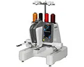
Preparing the thread guide assembly
Assemble the thread guide assembly. Locate the included
Phillips screwdriver.
a
Remove the two screws from the thread guide
assembly support.
b
Slide the thread guide assembly support onto the
machine, and then tighten the screw, until the thread
guide assembly support is secure.
c
Tighten the screw on the opposite side of the thread
guide assembly support in the same manner.
1 Lock nut
2 Adjustable foot nut
1 Adjustable foot nut
1 Lock nut
Note
• Do not apply extreme force when moving the
thread guide assembly support and thread guide
assembly.
• Be sure to tighten each screw well enough that the
thread guide assembly is secured.
Loading ...
Loading ...
Loading ...