Loading ...
Loading ...
Loading ...
55
31-1000600 Rev. 0
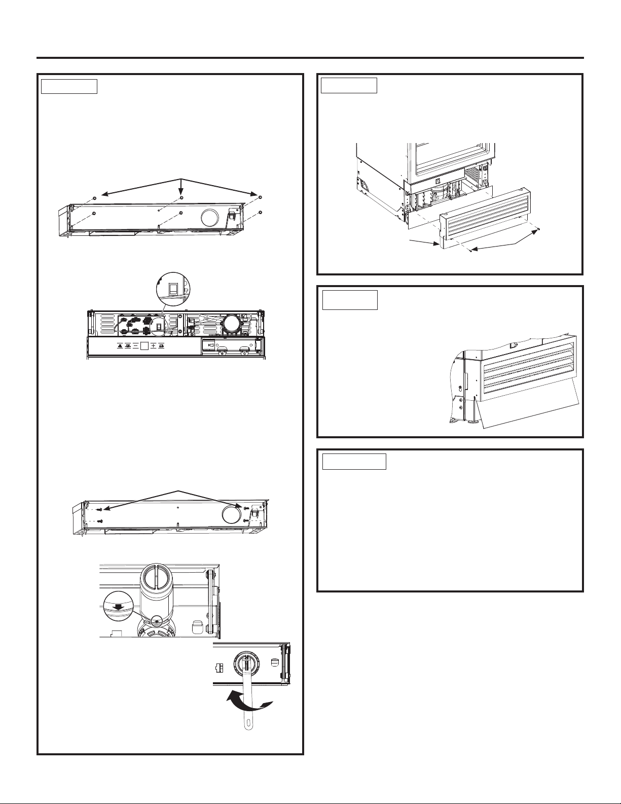
Installation Instructions - Single Integrated Installation
Ŷ Make sure lights are on inside the unit. If they are not
on, check to make sure the master switch is on by
removing the front enclosure which is secured with
six 1/4” Hex screws.
Ŷ Switch on the master switch if not on. (Master Switch
Wires hidden for clarity.
Ŷ Assemble the enclosure with removed screws.
Ŷ Predrill 1/16” holes is both the sides of the surround
1/2” deep through holes in the enclosure.
Ŷ Secure unit by driving four 1/4” hex screws to both
sides to surrounding cabinetry. NOTE: This step does
NOT replace the anti-tip safety hardware. Refer to
Step 4 Installing Anti-Tip Bracket and Step 7 Inserting/
Securing into Cabinet Surround for details on installing
the anti-tip hardware. Repeat for the second unit.
Ŷ/RFDWHEOXHDUURZRQ¿OWHU5RWDWH¿OWHUWRDOLJQDUURZ
as shown.
Ŷ,QVHUW¿OWHULQWRSRVLWLRQDQGURWDWH
óWXUQFORFNZLVHXVH¿OWHUUHPRYDO
tool if needed).
Ŷ5HWXUQ¿OWHUUHPRYDOWRROWR
mounting hook.
Ŷ
Close the compartment door.
STEP 8
FINAL EXTERNAL UNIT
PREPARATION (Cont.)
1/4” Hex Screws
Master Switch
1/4” Hex Screws
STEP 10 INTERNAL UNIT
PREPARATION
Ŷ Remove all tape, cardboard, and foam from the unit
(foam shipping supports may be located behind the
left and right sides of each of the glass pan fronts on
Refrigerator models).
Ŷ Remove boxed door bins from shelves.
Ŷ Unbox and install door bins.
Ŷ Install door bin mats.
1/4” Hex
Screws
Access
Cover
Ŷ Put the access cover back onto the unit and secure
with two 1/4” hex head screws.
STEP 8
FINAL EXTERNAL UNIT
PREPARATION (Cont.)
STEP 9 TOE KICK INSTALLATION
Ŷ Insert Toe Kick into the slot in the Front Access
Cover by rotating it toward you.
Ŷ Push the bottom portion
of the Toe Kick towards
the product and slide into
place.
Loading ...
Loading ...
Loading ...