Loading ...
Loading ...
Loading ...
11
31-1000600 Rev. 0
Installation Instructions - Reversing the Door Swing
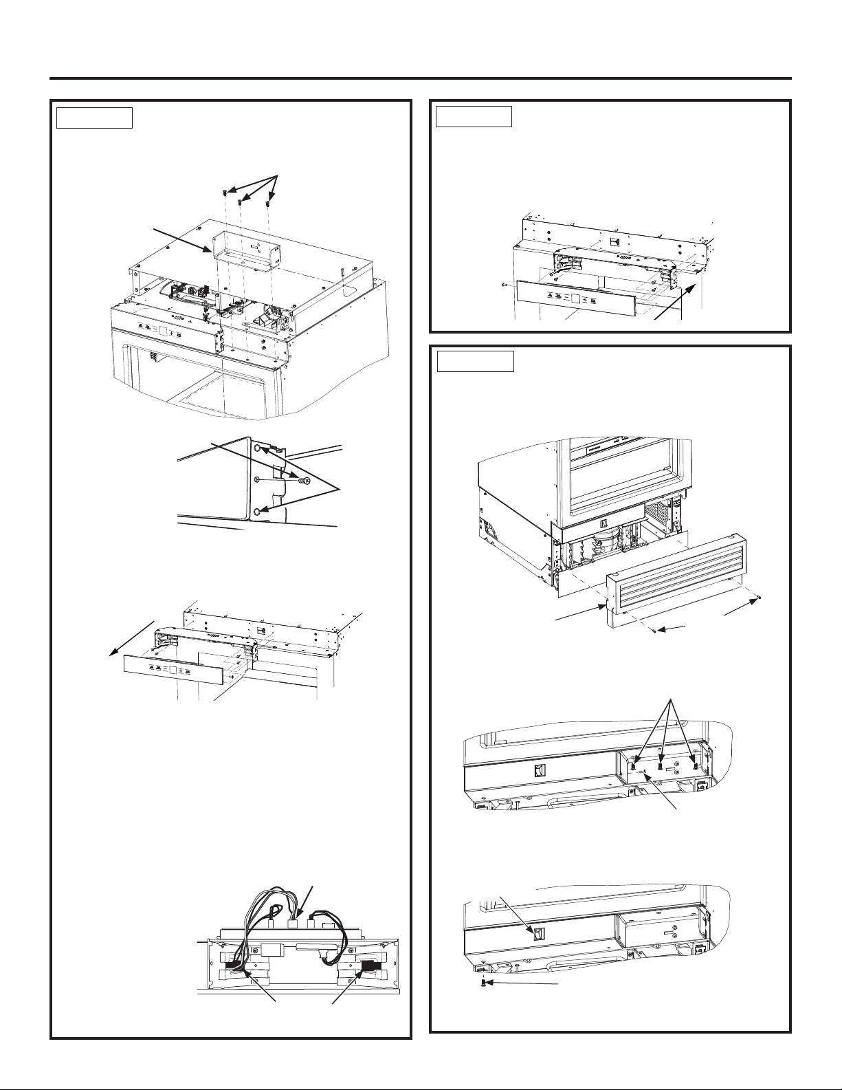
STEP 3
MOVE CONTROL ASSEMBLY
Ŷ Remove upper hinge brackets by removing the T-30
Torx screws.
Ŷ Remove the
Phillips head
screw from the
middle of the
housing on the
hinge side.
Ŷ Insert a flat head screwdriver or putty knife between
the glass front and plastic side and free the control
assembly by prying the plastic pins clear of the side
bracket holes.
Ŷ Lay the glass assembly on top of the control housing.
Ŷ Remove 4 screws, 2 on each end, to remove the
housing assembly using a 1/4” Hex bit.
Ŷ Move the housing assembly to the opposite side and
install using the 4 screws, 2 on each side.
NOTE: Make sure wires do not get pinched. On 18”
models, the red/white/black 5-pin wire connector
will need to be removed from the control board and
routed through the opposite corner bracket and
reconnected to the
control board to
prevent pinching
the wiring.
STEP 3
MOVE CONTROL ASSEMBLY
(Cont.)
Ŷ Snap glass assembly back onto the control housing
assembly, ensuring plastic pins snap into holes on
the side of the housing.
STEP 4 MOVE LIGHT SWITCH
HOUSING
Ŷ Remove front access cover from unit by removing
two 1/4” hex head screws.
Ŷ Remove the Philip screw first and lower hinge
brackets by removing three T-30 Torx screws.
Ŷ Remove screw with 1/4” hex bit driver at the bottom
corner of light switch housing.
Plastic Pins
(Both sides)
Screw
5-pin wire connector
Wires must be rerouted from one
side to the other for 18” models.
Access Cover
1/4” Hex Head
Screws
Upper Hinge
Bracket
T-30 Torx screws
Phillips Screw
T-30 Torx Screws
Phillips Screw
Light Switch
Loading ...
Loading ...
Loading ...