Loading ...
Loading ...
Loading ...
32
31-1000600 Rev. 0
Installation Instructions - Dual Retro-Fit Installation
FLOORING
For proper installation, this product must be placed on a level
surface of hard material that is at the same height as the rest of
the flooring. This surface should be strong enough to support a
fully loaded refrigerator or freezer, or approximately 1,200 lbs.
per unit.
NOTE: Protect the finish of the flooring.
NOTE: Not recommended for installation on carpeted flooring.
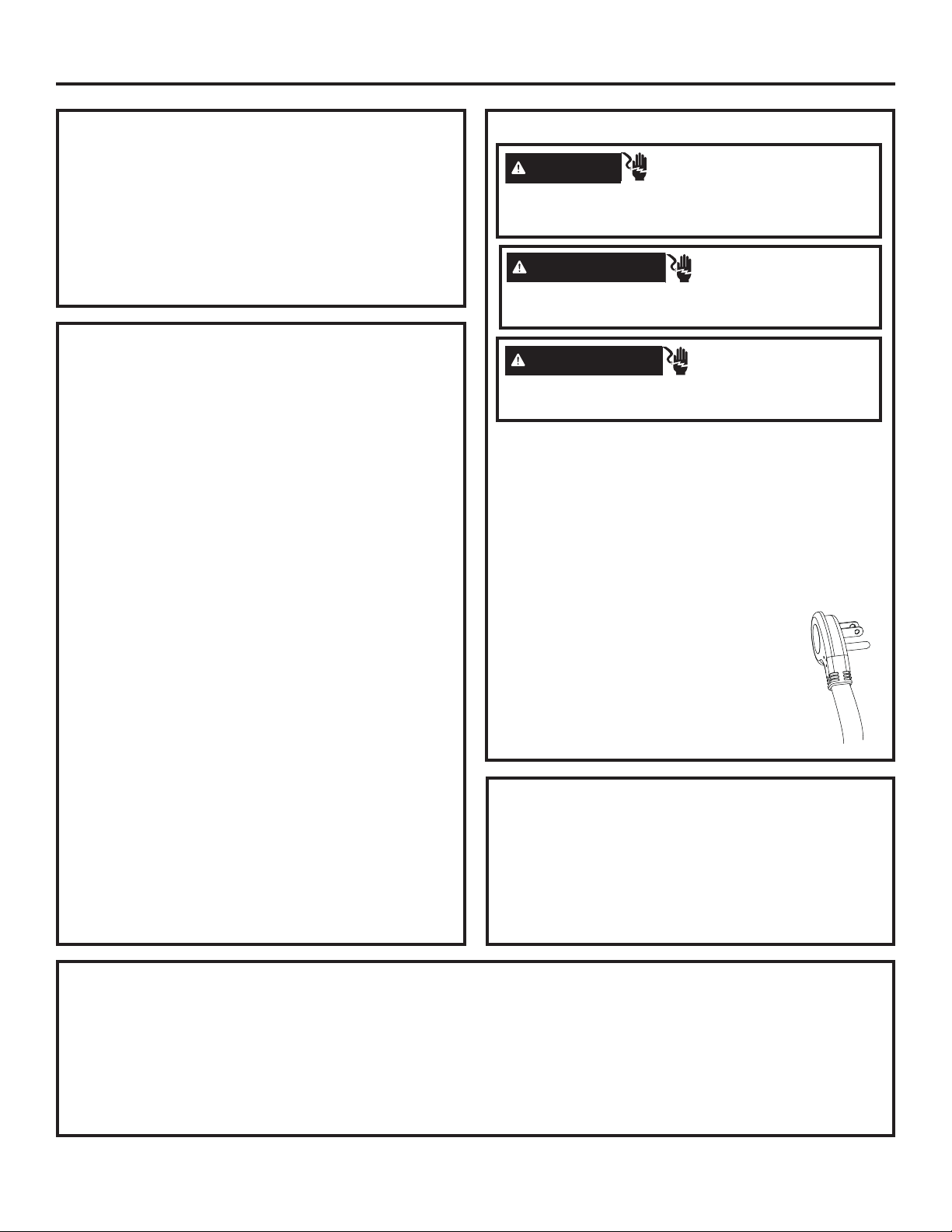
GROUNDING THE UNIT
The power cord of this appliance is equipped with a 3-prong
(grounding) plug which mates with a standard 3-prong
(grounding) wall receptacle to minimize the possibility of elec-
tric shock hazard from this appliance.
Have the wall outlet and circuit checked by a qualified
electrician to make sure the outlet is properly grounded.
Where a standard 2-prong wall outlet is encountered, it is
your personal responsibility and obligation to have it replaced
with a properly grounded 3-prong wall outlet.
DO NOT, UNDER ANY CIRCUMSTANCES, CUT
OR REMOVE THE THIRD (GROUND) PRONG
FROM THE POWER CORD.
DO NOT USE AN ADAPTER PLUG TO
CONNECT THE REFRIGERATOR TO A
2-PRONG OUTLET.
DO NOT USE AN EXTENSION CORD WITH
THIS APPLIANCE.
REFRIGERATOR/FREEZER LOCATION
Ŷ Do not install the refrigerator/freezer where the temperature
will go below 55°F (13°C). It will not run often enough to
maintain proper temperatures.
Ŷ Do not install the refrigerator/freezer where temperatures
will go above 100°F (37°C). It will not perform properly.
Ŷ Do not install the refrigerator/freezer in a location exposed
to water (rain, etc.) or direct sunlight.
Ŷ Install it on a floor strong enough to support it fully loaded.
TOOLS AND MATERIALS REQUIRED
• Metal shears
• #1, #2 Phillips screwdriver
• Flathead screwdriver
• Putty knife
• Measuring tape
• Drill and 1/16”, 5/64”, 3/16”, 1/2” bits
• 5/32” concrete bit (if installing anti-tip into concrete)
• 1/4”, 3/8”, 7/16” driver/socket
• 7/16” open wrench
• T10, T20, T30 driver/bit
• 1/8”, 1/4” hex driver (allen wrench)
• Level
• Water shut-off valves (optional but recommended)
• 8’ waterline (one per unit requiring water hookup)
• Masking tape
• Rubbing alcohol
• Adjustable wrench
• Center punch
• Heater Unification Kit (ZKUN)
• Stainless Steel Door Kits (if applicable)
• Custom panels for doors (if applicable)
• Handle Kits (if applicable)
• Small Rachet
• 42” (ZKR42N) or 48” (ZKR48N) Trim Retro Kit
• 42” (ZKK42P) or 48” (ZKK48P) Stainless Steel Toe Kick
HARDWARE SUPPLIED (per unit)
• Water Filter Bypass Plug
(if equipped)
• Air filter (if equipped)
• Anti-Tip bracket
• 3 Lag screws
• 3 Tapcon screws
• 3 Toggles with bolts
• Panel installation templates
• 2 Door trims
• 2 Door panel brackets
• Set screws
• #6 Phillips head wood screws
• Door Bracket Cover Top
• T30 screws
• 1 Hinge limiter pin
• Center door panel bracket
• Hi-Lo screw and square washer
• Access Cover
• Painted access cover screws
• T10 screws
WARNING
Electrical Shock
Hazard. Failure to follow these instructions can result
in death, fire, or electrical shock.
AVERTISSEMENT
Risque d’électrocution
Le non-respect de ces instructions peut occasionner un
décès, un incendie ou un choc électrique
ADVERTENCIA
Riesgo de Descarga
Si no se siguen estas instrucciones, se podrá producir
la muerte, incendios o descargas eléctricas.
Loading ...
Loading ...
Loading ...