Loading ...
Loading ...
Loading ...
54
31-1000600 Rev. 0
Installation Instructions - Single Integrated Installation
STEP 7 LEVEL UNIT
All models have 4-point leveling. The front is supported
by leveling legs; the rear is supported by adjustable
wheels. Both are accessible from the front of the unit.
Ŷ To level the back of the unit, turn the 7/16” hex nut
located above the front leveling legs. Turn clockwise
to raise or counterclockwise to lower the unit.
Ŷ)RUIURQWOHYHOLQJXVHD7ELWDWWKHWRSRIWKH
leveling leg or a 7/16” open-end wrench at the bottom
of the leveling leg.
Ŷ$GMXVWKHLJKWRIXQLWWRPDWFKLQVWDOODWLRQFXWRXW
opening 84”. The unit should be level and plumb with
cabinetry.
STEP 7 LEVEL UNIT
NOTICE: The rear leveling wheels and front leveling
legs are limited to a maximum height adjustment of 1”.
If the installation requires more than 84” height, the
installer should elevate the unit on a sheet of plywood
or runners. Cabinetry trim could also be added across
the top of the opening to shorten the opening. If you
attempt to raise the unit more than 1”, you will damage
the front leveling legs and the rear leveling wheels.
STEP 8
FINAL EXTERNAL UNIT
PREPARATION
FOR FLUSH INSTALLATION: Make sure front surface
of the door is 7/8” behind front face of surrounding
cabinets BEFORE securing brackets to the surrounding
cabinetry.
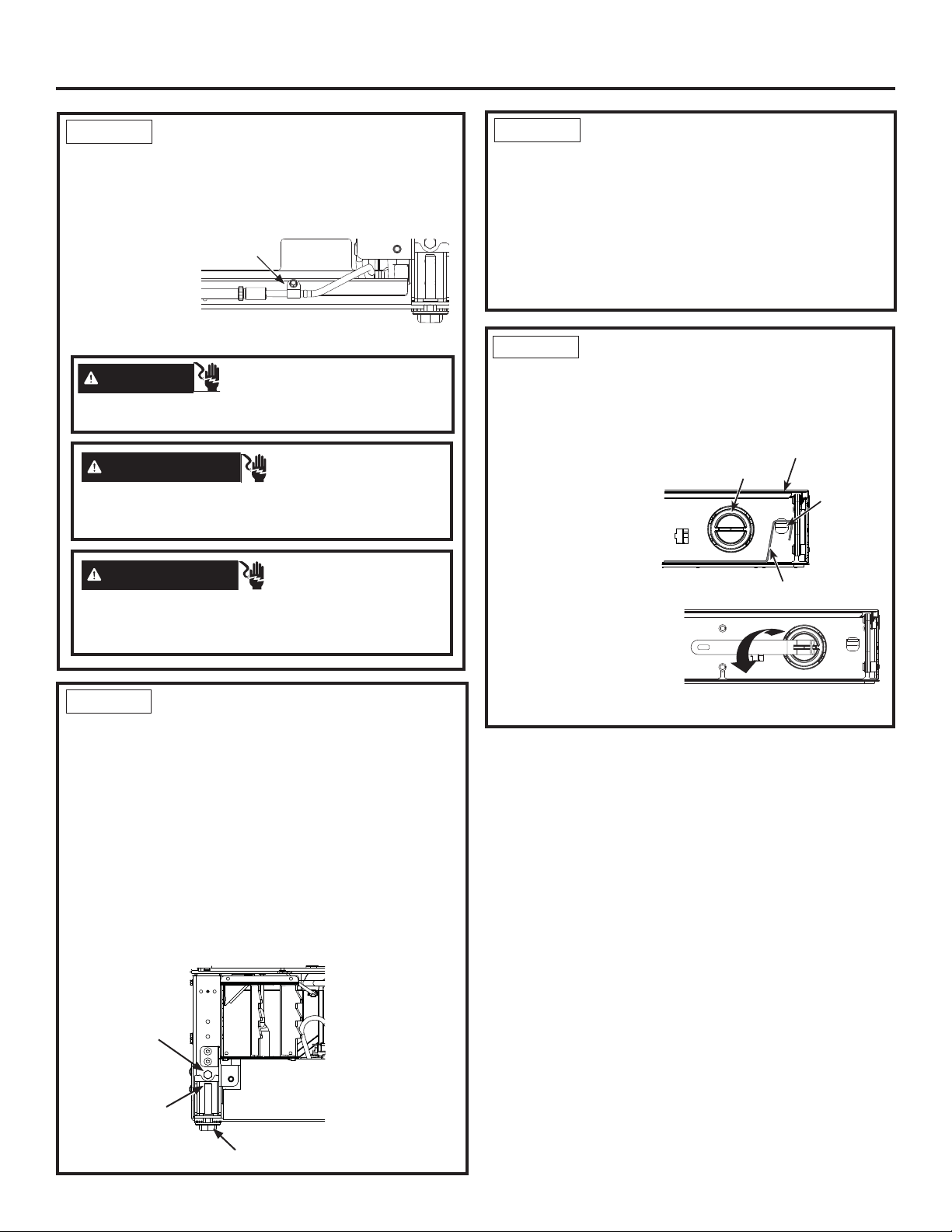
Ŷ Open the doors to
the units. Locate
¿OWHUDQG¿OWHU
removal tool.
Filter should be as
shown.
Ŷ5RWDWH¿OWHUóWXUQ
counterclockwise (use
¿OWHUUHPRYDOWRROLI
needed).
Ŷ3XOO¿OWHUWRZDUG\RXWR
remove. NOTE: Water
V\VWHPZLOOQRWIXQFWLRQZLWKRXW¿OWHULQSODFH
Filter Removal Tool
Filter
Mounting
Hook
Compartment Door
STEP 6 INSERTING/SECURING
INTO CABINET SURROUND
Ŷ As you walk the unit back into the opening, you
should pull the string tight to make sure the power
cord is routed underneath the unit.
Ŷ Replace the
waterline strain
relief screw.
Ŷ Store the
excess string
and water
tubing under the unit.
WARNING
Electrical Shock Hazard.
Replace waterline strain relief in front rail location as
shown.
Strain Relief
Screw
AVERTISSEMENT
Risque
d’électrocution.
Reposez la vis de décharge de
tension dans le profilé avant comme illustré.
ADVERTENCIA
Riesgo de Descarga
Eléctrica
Reemplace el amortiguador de refuerzo de
la tubería de agua frente a la ubicación del riel, como se
muestra.
T30 bit
adjusts front
leveling legs
7/16” hex nut
adjusts rear
wheels
7/16” open end wrench
adjusts front leveling legs
Loading ...
Loading ...
Loading ...