Loading ...
Loading ...
Loading ...
1 Product Introduction D-Link Smart Managed Switch User Manual
4
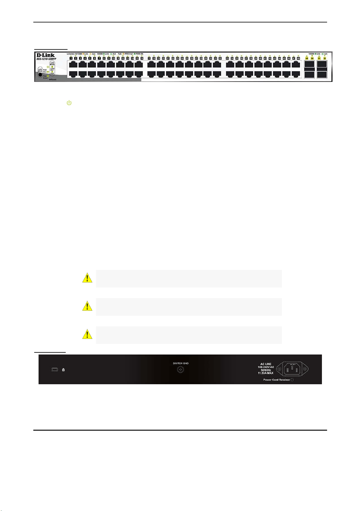
Front Panel
Figure 1.3 – DGS-1210-52MPP Front Panel
Power LED
: The Power LED lights up when the Switch is connected to a power source.
Fan Error: The FAN LED shows the status of the fans, light off indicates all fans work fine and the red light
indicates that one or multiple fans are working abnormally.
PWR Max: The Pwr Max LED lights up with solid red when the Switch reaches the maximum power budget
defined by the administrator via PoE System Settings page of Web GUI or the default power budget of 740
Watts.
LED Mode: To select the mode of port LED, the Link/Act and PoE LED under the mode button will solid
green to indicate which mode is selected.
Port Link/Act/Speed LED (1-48): The Link/Act/Speed LED flashes, which indicates a network link through
the corresponding port. Blinking indicates that the Switch is either sending or receiving data to the port.
When a port has an amber light, this indicates that the port is running on 10M or 100M. When it has a green
light it is running on 1000M.
Port Link/Act/Speed LED (49F, 50F, 51F, 52F): The Link/Act/Speed LED flashes, which indicates a
network link through the corresponding port. Blinking indicates that the Switch is either sending or receiving
data to the port. When a port has a green light, this indicates that the port is running on 1000M
Reset: Press the Reset button for 1~5 seconds to reboot the device. Press the Reset button for 6~10
seconds to reset the Switch back to the default settings and led will be solid light with amber for 2 seconds.
Or press the Reset button over 11 seconds to enter the loader mode after device reboot and the led will be
solid light with green for 2 seconds. If the device cannot reboot the Switch via image 1 and image 2, the
device will enter the loader mode automatically.
LED Mode: By pressing the Mode button, the Port LED will switch between Link/Act and PoE modes.
CAUTION: The MiniGBIC ports should use UL
listed Optical
Transceiver product, Rated Laser Class I. 3.3Vdc.
CAUTION: The port 1 ~ port 48 are PoE ports. When user press
the Mode button to PoE mode, only port 1 ~ port 48 will light up.
CAUTION: This equipment can
be connected only to PoE
networks without routing to the outside plant.
Rear Panel
Figure 1.4 – DGS-1210-52MPP Rear Panel
Power: Connect the supplied AC power cable to this port.
LED Indicators
The Switch supports LED indicators for Power, Fan, and Link/Act for each port. The following shows the LED
indicators for the DGS-1210 series Smart Managed Switch along with an explanation of each indicator.
Loading ...
Loading ...
Loading ...