Loading ...
Loading ...
Loading ...
UK/13
- Remove the rear panel (fig. 8 item.A)
- Disconnect the cables on the contactor and substitute it
- Perform the above operations in reverse order to reassemble.
5.3.5 TRANSFORMER REPLACEMENT
After carrying out the operations described in 5.1 above, to replace the
heating element proceed as follows:
- Remove the front lower panel (fig.8 item.G)
- Electrically disconnect the transformer and substitute it (table.A
item.18)
- Perform the above operations in reverse order to reassemble.
5.3.6 REPLACEMENT OF THE BAKING SURFACE
NOTE:
The Biscuit-ware surface is an excellent material for
baking and as such it must be always handled with extreme care;
every time it is removed, it is necessary to mark each biscuit-ware
element so to reposition them properly.
After carrying out the operations described in 5.1 for the
replacement/removal of the surface, proceed as follows:
- Using a blade as leverage, lift and remove the 2 mouth biscuit-ware
elements (fig.5 item I)
- Remove the Biscuit-ware elements, those that cannot be reached by
hand, use a pizza shovel
- Reposition the surface performing the same operations in reverse
order
NOTE:
At the end of the positioning, place the Biscuit-ware
elements in such a way that at the encter there is always the
minimum space.
5.3.7. REPLACEMENT OF THE SAFETY THERMOSTAT
WARNING!
Regularly check that the safety thermostat is
operating correctly.
After carrying out the operations described in 5.1 above, to replace the
safety thermostat proceed as follows:
- Open the sliding door and unscrew the two fastening screws of the
thermostat-holding panel (fig. 12 item 2)
Disconnect the thermostat faston connectors.
- Remove the right side panel (fig.5 item H)
- In the area close to the oven wall, remove the insulating panel (fig.16
item C) and move the mineral wool underneath it,
- Loosen up the two bracket screws and slide out the thermostat sensor
(fig.16 item H)
- Replace the thermostat (Table A Item 19) and carry out the operations
in reverse order to re-assemble, replacing, if necessary the insulation
removed previously.
5.3.8 HEATING ELEMENT REPLACEMENT
After carrying out the operations described in 5.1 above, to replace the
heating element proceed as follows:
- Remove the right and left side panels (fig.5 item H);
- Remove the lateral bands holding the wool
- Remove the right and left insulating panels
- Disconnect the supply wires of the heating element to be replaced;
- Remove with a blade the portion of mineral wool affected by the
operation;
- Unscrew the fastening screws and remove from the left and from the
right the brackets holding in position the heating elements;
- Slide out the heating element from within the refractory, making sure
to mark the position so that the heating elements can be reinserted in
the same seats;
- Perform the operations in reverse order to reassemble, replacing, if
necessary, the insulation removed previously.
5.4 REPLACING PARTS OF THE PROOFER
5.4.1 REPLACING THE LIGHT BULB
After carrying out the operations described in 5.1 above, to replace the
light bulb and/or cover from the inside of the proofer, proceed as follows:
- Unscrew the cover (fig. 17 item A) and replace the bulb (fig.17 item
B) and/or the cover itself.
- Screw back in the cover.
5.4.2 REPLACING THE DOOR HANDLE
After carrying out the operations described in 5.1 above, to replace the
heating element proceed as follows:
- Open the doors of the proofer (Fig. 5 Item L);
- Remove the two plastic caps from inside;
- Unscrew the fastening bolts of the screws (Fig.5 item M) making sure
not to make them fall inside the door;
- Replace the door handle and perform the above operations in reverse
order to reassemble.
5.4.3 THERMOSTAT REPLACEMENT
After carrying out the operations described in 5.1 above, to replace the
heating element proceed as follows:
- Open the sliding door and unscrew the two fastening screws of the
thermostat-holding panel (fig. 13A - 13B item 3)
- Disconnect the thermostat faston connectors;
- Remove the snap-on thermostat dial;
- Unscrew the locking ringnut of the thermostat;
- Open the compartment doors, remove the right tray holder guides,
remove the bulb thermostat protection cover (figure 5A item N) and
remove the safety bulb thermostat from its seat (figure 5A item M)
- Remove the front lower panel (fig.8 item.G)
- Remove the right side panel (fig.5 item H) and slide out the thermostat
bulb
- Replace the thermostat (item 7 plate B) and the respective sensor;
- Perform the above operations in reverse order to reassemble.
REPLACING THE INDICATOR LIGHT AND THE LIGHT
SWITCH
After carrying out the operations described in 5.1 above, to replace the
heating element proceed as follows:
- open the sliding door and unscrew the two fastening screws of the
compartment control panel (fig.13A-13B)
- Disconnect the faston connectors for the indicator and/or the light
switch.
- Replace the light indicator (fig.13A-13B item 1);
- Replace the light switch (fig.13A-13B item 2);
- Perform the above operations in reverse order to reassemble.
5.4.5 HEATING ELEMENT REPLACEMENT
After carrying out the operations described in 5.1 above, to replace the
heating element proceed as follows:
- Open the doors of the comparment, remove the rack guides and
disassembles the heating element protection covers
- unscrew the heating element bracket holder screws (fig.5A item P);
- Disconnect the heating element supply wires;
- Remove the heating elements (fig.5A item R);
- Perform the above operations in reverse order to reassemble the new
elements.
5.6 DISPOSAL
When the appliance or its spare parts are dismantled, the various
components must be sorted by type of material and disposed of in
compliance with current local laws and regulations.
The presence of a wheeled dustbin with a line
through it indicates that within the European
Union electrical components are subject to special
collection at the end of their working life. As well
as to this device, this standard applies to all
accessories marked with this symbol. Do not
dispose of these products along with other
household waste
6 LIST OF SPARE PARTS
Index of plates
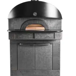
Tab. A NEAPOLIS baking chamber assembly
Tab. B Proofer assembly
Tab. C NEAPOLIS electrical diagram
Tab. D Proofer electrical diagram
INSTRUCTIONS FOR ORDERING SPARE PARTS
Orders for spare parts must contain the following information:
- Appliance type
- Appliance serial number
- Name of part
- Quantity required
Loading ...
Loading ...
Loading ...