NEAPOLIS
6P
NEAPOLIS 9P
Forno elettrico
Electric oven
Four electrique
Manuale di istruzioni
Instructions manual
Manuel d’instructions
Numeri di matricola / Serial numbers :
Cod.73303240
Ver.: A02

IT/1
NOTA SULLA SICUREZZA
Non tenere o usare benzina o altri liquidi infiammabili in prossimità di
questa o
di
qualsiasi altra
apparecchiatura
.
AVVERTENZA
Un'installazione errata o interventi di regolazione, modifica,
assistenza o manutenzione non corretti possono provocare
danni
materiali, lesioni personali o addirittura causare la morte.
Prima di installare o
effettuare un intervento di assistenza su
questa apparecchiatura, leggere attentamente le istruzioni per
l'installazione, il funzionamento e la manutenzione del
dispositivo.
AVVISO
L'uso di parti di ricambio non originali, cioè non prodotti dalla Moretti
Forni, fanno decadere la garanzia
e
la responsabilità da parte del
produttore
.
AVVISO
La garanzia dell'apparecchiatura è da considerarsi valida
esclusivamente se un installatore autorizzato
ha
installato e avviato il
forno dando inoltre una dimostrazione sul relativo
f
unzionamento
.
AVVISO
Moretti Forni (il produttore) si riserva il diritto di cambiare le specifiche
in qualsiasi
momento
.
AVVISO
Lo schema elettrico è disponobile nella sezione 6 di questo manuale.
Conservare il presente manuale come riferimento futuro

IT/2
INDICE
01 SPECIFICHE TECNICHE
3
02 INSTALLAZIONE
3
03 FUNZIONAMENTO
5
04 MANUTENZIONE E PULIZIA
9
05 MANUTENZIONE STRAORDINARIA
11
06 CATALOGHI RICAMBI
12
Nota:
Il presente manuale é predisposto per la lettura in tre lingue. Istruzioni originali in Italiano e traduzioni delle istruziuoni originali in Inglese, Francese.
Per una miglior chiarezza e lettura, il presente manuale, potrebbe essere fornito in più parti separate e può essere spedito via mail contattando la Ditta
Costruttrice.
GARANZIA
Norme e regolamentazione
La garanzia è limitata alla pura e semplice sostituzione franco fabbrica del pezzo eventualmente rotto o difettoso, per ben accertato difetto di materiale o
costruzione. Non sono coperte da garanzia le eventuali avarie causate dal trasporto effettuato da terzi, da erronea installazione e manutenzione, da
negligenza o trascuratezza nell’uso, da manomissioni da parte di terzi. Inoltre sono esclusi dalla garanzia: i vetri, le calotte, le lampadine, i piani in
refrattario/biscotto/granito e quanto altro in dipendenza del normale logorio e deperimento dell’impianto e di ogni suo accessorio; nonché la
manodopera necessaria alla sostituzione di eventuali parti in garanzia.
La garanzia decade se il compratore non è in regola con i pagamenti e per i prodotti eventualmente riparati, modificati o smontati anche solo in parte senza
autorizzazione scritta preventiva. Per ottenere l’intervento tecnico in garanzia, dovrà essere inoltrata richiesta scritta al concessionario di zona o alla
Direzione Commerciale.
ATTENZIONE
Questa dizione indica pericolo e verrà utilizzato tutte le volte che viene coinvolta la sicurezza dell’operatore.
NOTA
-Questa dizione indica cautela e vuole richiamare l’attenzione su operazioni di vitale importanza per un funzionamento corretto e duraturo
dell’apparecchiatura.
GENTILE CLIENTE
Prima di iniziare l’utilizzo di questo forno, leggere il presente manuale.
Per la sicurezza dell’operatore, i dispositivi dell’apparecchiatura devono essere tenuti in costante efficienza.
Questo libretto ha lo scopo di illustrare l’uso e la manutenzione; l’operatore ha il dovere e la responsabilità di seguirlo.
ATTENZIONE!
1. Quanto descritto riguarda la vostra sicurezza.
2. Leggere attentamente prima dell’installazione e prima dell’uso dell’apparecchiatura.
3. Conservare con cura questo libretto per ogni ulteriore consultazione dei vari operatori.
4. L’installazione deve essere effettuata secondo le istruzioni del costruttore da personale qualificato.
5. Quest’apparecchiatura dovrà essere destinata solo all’uso per il qual è stata espressamente concepita, e vale a dire per la cottura di pizze o
prodotti alimentari analoghi. E’ vietato eseguire cotture con prodotti contenenti alcool. Ogni altro uso è da ritenersi improprio.
6. L’apparecchiatura è destinata unicamente all’uso collettivo e deve essere usata da un utilizzatore professionale qualificato ed addestrato
all’uso della stessa. L’apparecchio non è destinato ad essere utilizzato da persone (bambini compresi) le cui capacità fisiche, sensoriali o
mentali, siano ridotte, oppure con mancanza di esperienza o di conoscenza. I bambini devono essere sorvegliati per sincerarsi che non giochino
con l’apparecchio.
7. Per l’eventuale riparazione rivolgersi esclusivamente ad un centro d’assistenza tecnica autorizzato dal Costruttore e richiedere l’utilizzo di
ricambi originali.
8. Il mancato rispetto di quanto sopra può compromettere la sicurezza dell’apparecchiatura.
9. In caso di guasto e/o cattivo funzionamento disattivare l’apparecchio astenendosi da qualsiasi tentativo di riparazione o d’intervento diretto.
10. Se l’apparecchio dovesse essere venduto o trasferito ad un altro proprietario o se dovesse traslocare e lasciare installata l’apparecchiatura,
assicurarsi sempre che il libretto accompagni l’apparecchio in modo che possa essere consultato dal nuovo proprietario e/o dall’installatore.
11. Se il cavo di alimentazione è danneggiato, esso deve essere sostituito dal servizio di assistenza tecnica abilitato dalla ditta costruttrice, in modo
da prevenire ogni rischio.
IT/3
1 SPECIFICHE TECNICHE
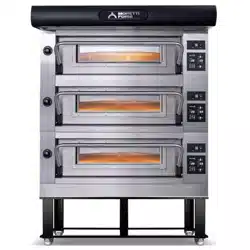
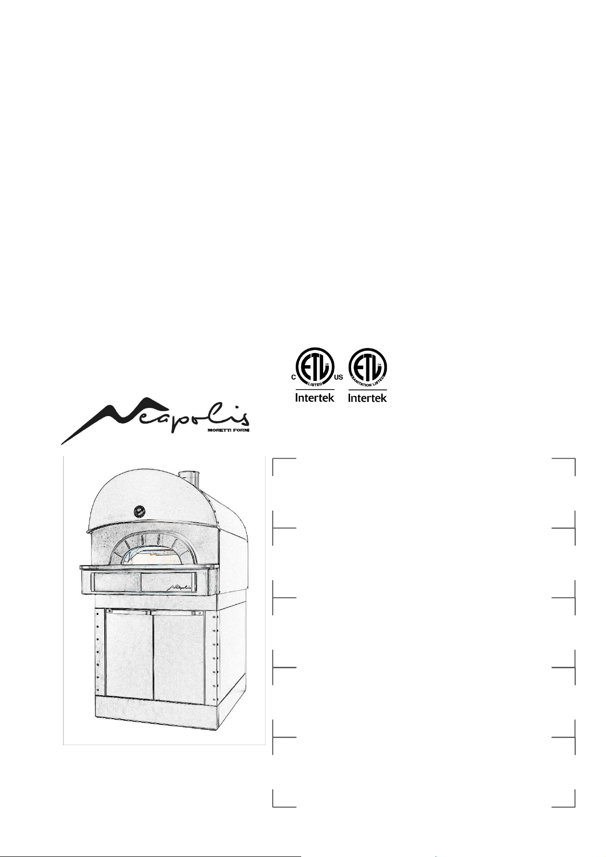
1.1 DESCRIZIONE DELLE APPARECCHIATURE
L’apparecchiatura è costituita da due moduli sovrapposti:
- Camera/e di cottura completa di cappa
- Cella di lievitazione
La camera di cottura ha la regolazione della temperatura di tipo
elettronico ed è dotata di termostato di sicurezza; internamente la camera
è in materiale refrattario.
La cella di lievitazione è costituita da una struttura in acciaio, è
pannellata, ha guide portateglie e può essere dotata di termostato per il
riscaldamento.
1.2 DIRETTIVE APPLICATE
UL STD 197
NSF STD 4
CAN/CSA C22.2 STD No.109
1.3 POSTAZIONI DI LAVORO
Le apparecchiature vengono programmate dall’operatore sui quadri
comandi posti sulla parte frontale dell’apparecchiatura e durante il loro
funzionamento devono essere sorvegliate.
Gli sportelli di accesso della cella di lievitazione sono posti sulla parte
frontale dell’apparecchiatura.
1.4 MODELLI
I modelli previsti sono:
- NEAPOLIS 6P
- NEAPOLIS 9P
1.5 DIMENSIONI DI INGOMBRO E PESI (Vedi Tabelle)
1.6 DATI TECNICI (Vedi Tabelle)
1.7 IDENTIFICAZIONE
Per qualsiasi comunicazione con il produttore o con i centri assistenza
citare sempre il NUMERO DI MATRICOLA dell’apparecchiatura che è
apposto sulla targhetta fissata nella posizione in fig.1.
1.8 ETICHETTATURE
Nei punti mostrati in fig. 1 e 2, l’apparecchiatura è dotata di targhette di
attenzione riguardanti la sicurezza:
B - Etichetta "PROOFER SANITATION"
C - Etichetta "FITTING FUSES"
D - Etichetta "CONNECTION 8 AWG" or "CONNECTION 6
AWG"
E - Etichetta "PREVENTION OF FIRE AND ELECTRIC
SHOCKS"
F - Etichetta "ELECTRIC U.S. AND CANADA AND
SANITATION"
G – Etichetta "HOT SURFACE"
H - Etichetta "PHASE IDENTIFICATION"
L - Etichetta "DISTANCE FROM WALL"
M – Etichetta "RISK OF ELECTRIC SHOCK"
N – Etichetta "SERVICE"
O – Etichetta "LAMP"
Inoltre l’apparecchiatura è dotata di targhette di attenzione riguardanti la
sicurezza.
ATTENZIONE!
Nella superficie dell’apparecchiatura è
presente un pericolo di ustione dovuto alla presenza di elementi a
temperatura elevata. Per qualsiasi tipo d’intervento o qualsiasi
operazione attendere che l’apparecchiatura scenda alla temperatura
ambiente ed utilizzare sempre opportuni dispositivi di protezione
individuale (guanti, occhiali…).
ATTENZIONE!
Presenza di tensione pericolosa. Prima di
effettuare qualsiasi operazioni di manutenzione, interrompere
l'alimentazione elettrica spegnendo gli interruttori installati
esternamente al forno e/o alla cella di lievitazione ed attendere che
l’apparecchiatura scenda alla temperatura ambiente. Utilizzare sempre
opportuni dispositivi di protezione (guanti, occhiali... ).
1.9 ACCESSORI
Le apparecchiature sono dotate dei seguenti accessori:
Modello Accessorio
NEAPOLIS
forno statico
CELLA DI LIEVITAZIONE RISCALDATA
Un eventuale supporto non fornito dalla ditta costruttrice deve essere
idoneo a garantire in ogni situazione la corretta stabilità
dell’apparecchiatura; inoltre deve assolutamente lasciare aperte tutte le
asole di aerazione presenti perimetralmente nella parte inferiore del
forno.
1.10 RUMORE
Quest’apparecchio è un mezzo tecnico di lavoro, che normalmente nella
postazione dell’operatore non supera la soglia di rumorosità di 70 dB
(A).
2 INSTALLAZIONE
2.1 TRASPORTO
L’apparecchiatura viene spedita normalmente montata su bancali in
legno con mezzi di trasporto via terra (fig.3).
È assolutamente vietato trasportare e movimentare l’apparecchiatura
sulle sue ruote, deve essere sempre sopra il suo supporto in legno, in
modo che le ruote rimangano libere e leggermente sollevate da terra;
utilizzare appositi mezzi di sollevamento e trasporto (transpallet, muletto
ecc.).
I singoli pezzi sono protetti da un film di plastica o scatole in cartone o
cassa di legno.
2.2 SCARICO
NOTA:
Al momento della consegna si consiglia di controllare
lo stato e la qualità dell’apparecchiatura.
NOTA:
Il pannello di comando della Cella di lievitazione
TERMOREGOLATA è posto sul quadro comandi del forno, quindi
se il forno e la cella devono essere divisi procedere come segue:
- smontare il pannello laterale destro del forno (fig.5 part. H)
- scollegare la morsettiera del forno dalla morsettiera della cella (fig.5A
part.I e L)
- Aprire gli sportelli della cella, togliere le guide portateglie a destra,
smontare il Carter protezione bulbo terrmostato (fig.5A part.N) e sfilare
il bulbo del termostato di sicurezza dalla sua sede (fig.5A part.M)
- Al termine dell’installazione eseguire le operazioni inverse per il
rimontaggio
ATTENZIONE!
Utilizzare idonei mezzi di sollevamento.
Sollevare l’apparecchiatura utilizzando solo ed esclusivamente i
punti indicati in fig.4B per il forno ed in fig.4E per la cella di
lievitazione; per eventualmente applicare gli agganci per il
sollevamento del forno (fig.4A part. F), devono essere smontati
prima i due pannelli laterali della camera di cottura (fig.5 part. H) e
poi montati i 4 agganci ognuno con 6 viti come indicato in fig. 4A. Se
necessario agganciarsi con il mezzo di sollevamento in maniera
diversa dai 4 fori di aggancio superiori, usare i 2 trasversali lunghi
(codice 72016150 tubolare in acciaio 60x30x3mm L=3mt, opzionale
come Kit di sollevamento), inseriti come indicato in fig. 4C posizione
D o E a seconda della necessità.
Alla fine delle operazioni smontare i 4 agganci per sollevamento e
montare i 2 pannelli laterali (fig.5 part. H).
Se viene spostata la Cella di Lievitazione mediante Transpallet,
FARE SEMPRE ATTENZIONE CHE IL PESO SIA BEN
BILANCIATO e CHE LE FORCHE ASSOLUTAMENTE
SPORGANO DALLA PARTE OPPOSTA AL LATO DI
INGRESSO (fig.4D).
2.2.1 INCLINAZIONE CAMERA DI COTTURA
Se dovesse servire inclinare il forno per attraversare un passaggio
minimo di 68cm procedere come segue:
NOTA:
Il piano di cottura in Biscotto è un ottimo materiale per
cuocere, ma è delicato pertanto deve essere trattato sempre con
molta cura; se nella movimentazione la camera di cottura deve
IT/4
essere inclinata, prima il piano in cottura in Biscotto deve essere
tolto, segnando la posizione di ogni Biscotto in modo da poterli
riposizionare nella giusta posizione al termine dell’installazione.
- Smontare nell’ordine:(riferimento fig.4A): la cappa frontale (G), i
pannelli laterale (fig.5 part.H) se presenti, i carter superiori (H), la
facciata anteriore (I) svitando anche le viti all’interno della bocca del
forno, il condotto vapori interno (L), il pannello posteriore (A), la
facciata posteriore (M).
- Applicare gli agganci per il sollevamento (fig. 4A part.F) ed appoggiare
il forno di lato su di essi per poterlo spostare, una volta effettuato
l’attraversamento eseguire le operazioni inverse per il rimontaggio,
NOTA:
Il forno può essere inclinato di 90° solo per attraversare
un passaggio stretto e poi riportato in posizione orizzontale,
ASSOLUTAMENTE NON PUÒ MAI ESSERE TRASPORTATO
lNCLINATO
2.3 SPECIFICHE AMBIENTALI
Per il buon funzionamento dell’apparecchiatura è consigliabile che i
valori ambientali abbiamo i seguenti limiti:
Temperatura di esercizio: +5° C ÷ +40°C (+41°F ÷ +104°F)
Umidità relativa: 15% ÷ 95%
2.4 POSIZIONAMENTO, MONTAGGIO E SPAZI
MANUTENTIVI
ATTENZIONE!
Durante il posizionamento, il montaggio
e l’installazione sono da rispettare le seguenti prescrizioni:
- Leggi e norme vigenti relative ad installazioni di apparecchiature
elettriche
- Direttive e determinazioni dell’ente erogatore di elettricità
- Regolamenti edilizi ed antincendio locali
- Prescrizioni vigenti antinfortunio
- Determinazioni vigenti del CEI
ATTENZIONE!
L’apparecchiatura deve essere installata
su una superfice stabile e piana, a bolla. L’apparecchiatura non deve
mai venire a contatto con materiali infiammabili o combustibili.
NOTA:
Collocare il forno in modo che le correnti d’aria non
possano arrivare nelle vicinanze della bocca della camera di cottura,
altrimenti potrebbero disturbare la cottura.
I singoli moduli prescelti per la configurazione del forno devono essere
sovrapposti come specificato in figura 5, infilando i piedini di
riferimento di ciascun modulo nella sede di quello sottostante (fig.5
part.A).
Il forno va posizionato in un luogo ben aereato.
I seguenti spazi minimi devono essere lasciati tra il forno e qualsiasi
superficie combustibile o non combustibile (vedi figura 6):
NEAPOLIS
6P-9P
A B C
Distanze 0” (0cm) 0” (0cm) 0” (0cm)
Service 20” (50cm) 20” (50cm) 20” (50cm)
Tenere conto del fatto che per alcune operazioni di pulizia /
manutenzione / service, la distanza deve essere maggiore di quanto
indicato e quindi considerare la possibilità di poter spostare il forno allo
scopo di eseguire queste operazioni.
ATTENZIONE! Dopo l'assemblaggio finale del forno, un cordone di
silicone approvato NSF deve essere eseguito attorno a tutte le
articolazioni per evitare l'ingresso di liquidi o sporcizia.
Il carter perimetrale di base della Cella di lievitazione viene fornito
smontato per permettere un’agevole movimentazione della cella su
ruote; vanno quindi montati prima i 2 carter Posteriore ed Anteriore
(fig.5 part.B e C) prestando attenzione che il rispettivo colore sia
uguale alla facciata su cui lo si monta.
- Inserire il carter posteriore (fig.5 part.B) nella sua sede e fermarlo con
2 viti per lato alle apposite staffe (fig.5 part.E), quindi avvitare le due viti
posteriori in dotazione (fig.5 part.P).
- Inserire il carter anteriore (fig.5 part.C) PRIMA SUL LATO
DESTRO E POI SUL LATO SINISTRO, fare agganciare le sue due
mollette interne (fig.5 part.S) alla loro sede (fig.5 part.R), poi fermarlo
con le 3 viti a destra e 2 viti a sinistra alle apposite staffe (fig.5 part.N).
- Posizionare il forno accertandosi che i freni delle ruote anteriori siano
accessibili; serrare i freni delle 2 ruote anteriori della cella spingendo con
un cacciavite le linguette di STOP (fig.4E part.STOP); successivamente
montare i 2 carter basculanti laterali (fig.5 part.F) ognuno mediante le
due viti (fig.5 part.G), i carter laterali sono basculanti per agevolare la
pulizia e permettere di accedere alle 2 ruote frontali di cui và premuto il
freno una volta posizionato il forno. Per il collegamento elettrico vedere
punto 2.5.2.2.
ATTENZIONE:
Se il forno deve essere spostato, prima
sollevare i 2 carter basculanti laterali (fig.5 part.F) e SBLOCCARE
I FRENI POSTI SULLE 2 RUOTE ANTERIORI DELLA CELLA
spingendo con un cacciavite le linguette di sgancio (fig.4E part.GO);
una volta giunti a destinazione riserrare i freni. Le ruote servono
SOLO ED ESCLUSIVAMENTE per lo spostamento all’interno del
laboratorio di cottura, al fine della pulizia e di minimi spostamenti
per manutenzione, e’ espressamente vietato eseguire spostamenti
diversi del forno sulle sue ruote; se necessario spostarlo utilizzare
appositi mezzi di sollevamento e trasporto (transpallet, muletto
ecc.). Se il forno deve essere ritraspostato deve essere riposizionato
sopra il suo supporto in legno, o equivalente, in modo che le ruote
rimangano libere e leggermente sollevate da terra.
NOTA:
Un apparecchio dotato di ruote deve essere provvisto di un
dispositivo (fig.5 part.Z) per fissare l'apparecchio alla struttura
dell'edificio per limitare il movimento dell'apparecchio in modo che la
tensione non venga trasmessa al condotto di alimentazione elettrica:
a) Devono essere previsti mezzi adeguati per limitare il movimento
dell'apparecchio senza dipendere o trasmettere stress al condotto
elettrico;
b) Devono essere specificati il (i) luogo (i) nel quale devono essere fissati
i mezzi di ritenuta all'apparecchio;
c) L'apparecchio deve essere installato utilizzando un condotto flessibile.
2.5 COLLEGAMENTI
2.5.1 COLLEGAMENTO SCARICO VAPORI
ATTENZIONE!
Il collegamento dello scarico vapori deve
essere effettuato esclusivamente da personale qualificato.
NOTA:
Il raccordo in dotazione con il forno (fig.7 part.A) è
consigliato nel casi di installazione con canna fumaria.
Nell’installazione sotto cappa può non essere montato.
II raccordo in dotazione con il forno (fig.7 part.A) deve essere inserito
nella sua sede nella parte superiore del forno, come da fig.7.
NOTA:
Collegare tale raccordo con una canna fumaria o con
l'esterno mediante un tubo consigliato di diametro 200m (minimo
150 mm collegato mediante idonea riduzione nella parte superiore
al raccordo d.200mm).
Il tubo (fig.7 part.B) deve essere inserito all’interno del raccordo (fig.7
part.A). Anche eventuali prolungamenti devono essere eseguiti in modo
che i tubi superiori entrino in quelli inferiori.
Il tiraggio potrà essere regolato grazie alla valvola manuale posta
sotto la cappa (vedere paragrafo 3.4), normalmente deve essere tutta
aperta, ma in presenza di una canna fumaria che tira molto và
regolata chiudendola fino a trovare il bilanciamento ideale.
2.5.2 COLLEGAMENTO ELETTRICO
ATTENZIONE!
Il collegamento elettrico deve essere
eseguito esclusivamente da personale qualificato, in conformità con
i requisiti Electrical Power Assurance Corporation vogenti. In
assenza di codici locali, i codici elettrici devono essere conformi al
National Electrical Code (NEC) ANSI / NFPA70 e al Canadian
Electrical Code CSA C22.2.
ATTENZIONE!
Il collegamento elettrico deve essere
effettuato esclusivamente da personale qualificato in osservanza
delle vigenti prescrizioni CEI.
Prima di iniziare la procedura di collegamento verificare che il
sistema di messa a terra sia realizzato in accordo alle norme europee
EN.
Prima di iniziare la procedura di collegamento verificare che
l’interruttore generale dell’impianto a cui va collegato il forno sia in
posizione "off".
La targhetta matricola contiene tutti i dati necessari per un corretto
collegamento.
2.5.2.1 COLLEGAMENTO ELETTRICO CAMERA DI
COTTURA
ATTENZIONE!
E’ necessario installare per ogni singolo
elemento di cottura, un interruttore generale quadripolare con
fusibili o un interruttore automatico idoneo ai valori riportati sulla
targhetta, che permetta di scollegare i singoli apparecchi dalla rete
e che consenta la disconnessione completa nelle condizioni della
categoria di sovratensione III.

IT/5
NOTA:
Il dispositivo scelto dovrebbe trovarsi nelle immediate
vicinanze dell’apparecchio ed essere posizionato in luogo facilmente
accessibile.
La camera di cottura viene consegnata con il voltaggio richiesto
segnalato sulla targhetta matricola (fig.1).
Per effettuare il collegamento elettrico, rimuovere il coperchio di
protezione posizionato sul lato posteriore della camera di cottura (Fig.8
part.A). Il cavo di collegamento deve essere fornito dall'installatore.Per
il collegamento alla rete elettrica è necessario installare una spina
standardizzata alle norme vigenti.
Inserire nell'apposito foro passacavo (Fig.8 part.B) il cavo di sezione
adeguata (Vedi dati tecnici) e collegarlo poi alla morsettiera come
illustrato rispettivamente in figura 9.
Inoltre queste apparecchiature devono essere comprese nel circuito del
sistema equipotenziale, il morsetto previsto a tale scopo si trova sul retro
dell'apparecchiatura (Fig.8 part.C) con il simbolo MORSETTO PER IL
COLLEGAMENTO EQUIPOTENZIALE.
Ad allacciamento eseguito controllare che la tensione di alimentazione,
a macchina funzionante, non si discosti dal valore nominale di ±5%.
ATTENZIONE!
Il cavo flessibile per l’allacciamento alla
linea elettrica deve essere di caratteristiche non inferiori al tipo con
isolamento in gomma HO7RN-F e deve avere una sezione nominale
adeguata all’assorbimento massimo (vedi dati tecnici).
NOTA:
VERIFICARE CHE LE FASI DI ALIMENTAZIONE
SIANO CORRETTE ED EFFICACI, RILEVARE LA
CORRETTEZZA DEGLI AMPERE ASSORBITI.
2.5.2.2 COLLEGAMENTO ELETTRICO CELLA DI
LIEVITAZIONE TERMOREGOLATA
Il pannello di comando della Cella di lievitazione è posto sul quadro
comandi del forno, quindi il forno e la cella devono essere collegati, per
fare ciò procedere come segue:
- Smontare il pannello laterale destro del forno (fig.5 part.H)
- Collegare alla morsettiera del forno (fig.5A part.L) i cavi della cella
(fig.5A part.I)
- Aprire gli sportelli della cella, togliere le guide portateglie a destra,
inserire il bulbo del termostato nella sua sede (fig.5A part.M) e rimontare
il Carter protezione bulbo terrmostato (fig.5A part.N)
- Rimontare il pannello laterale destro del forno (fig.5 part.H) e rimettere
le guide portateglie
ATTENZIONE!
E’ necessario installare per la cella, un
interruttore generale bipolare con fusibili o un interruttore
automatico idonei ai valori riportati sulla targhetta.
NOTA:
Il dispositivo scelto dovrebbe trovarsi nelle immediate
vicinanze dell’apparecchio ed essere posizionato in luogo facilmente
accessibile.
La cella di lievitazione viene consegnata col voltaggio segnalato sulla
targhetta matricola (fig.1).
Per il collegamento elettrico, togliere il coperchio di protezione posto sul
lato posteriore della cella (fig.8 part.D).
Il cavo di collegamento deve essere messo a disposizione
dall’installatore.
Per il collegamento alla rete elettrica è necessario installare una spina
standardizzata alle norme vigenti.
Inserire nell’apposito foro passacavo (fig.8 part.E) un cavo di sezione
idonea (Vedi dati tecnici), e collegarlo poi alla morsettiera come
illustrato in figura 11.
Ad allacciamento eseguito controllare che la tensione di alimentazione,
a macchina funzionante, non si discosti dal valore nominale di ±5%.
ATTENZIONE!
Il cavo flessibile per l’allacciamento alla
linea elettrica deve essere di caratteristiche non inferiori al tipo con
isolamento in gomma HO7RN-F e deve avere una sezione nominale
adeguata all’assorbimento massimo (vedi dati tecnici).
ATTENZIONE!
E’indispensabile collegare
correttamente l’apparecchiatura a terra.
A tale scopo, sulla morsettiera di allacciamento, è collocato
l’apposito morsetto (Fig.9-11) con il simbolo al quale deve essere
allacciato il filo di messa a terra.
Inoltre queste apparecchiature devono essere comprese nel circuito del
sistema equipotenziale, il morsetto previsto a tale scopo si trova sul retro
dell'apparecchiatura (fig.8 part.F) con il simbolo MORSETTO PER IL
COLLEGAMENTO EQUIPOTENZIALE.
3 FUNZIONAMENTO
3.1 OPERAZIONI PRELIMINARI DI CONTROLLO
ATTENZIONE!
Prima di iniziare le fasi di avviamento e
programmazione dell’apparecchiatura si deve verificare che:
- tutte le operazioni di collegamento elettrico e messa a terra siano
state eseguite correttamente.
- tutte le operazioni di collegamento scarico vapori siano state
eseguite correttamente.
NOTA:
Al termine dell’installazione, prima di accendere il
forno, accostare i Biscotti in maniera tale che al centro rimanga la
luce minima tra i biscotti.
Tutte le operazioni di controllo devono essere eseguite da personale
tecnico specializzato munito di regolare licenza.
ATTENZIONE!
- Mentre l’apparecchiatura è in funzione deve essere sorvegliata.
- Durante il funzionamento le superfici dell’apparecchiatura
diventano calde, in particolare nella zona della facciata della camera
di cottura, pertanto prestare attenzione a non toccarle per non
ustionarsi.
- All’apertura della porta tenersi a distanza di sicurezza da eventuali
vapori ustionanti che potrebbero fuoriuscire dalla camera di
cottura.
- Non fare avvicinare all’apparecchiatura persone non addette.
Per una maggiore uniformità si consiglia di evitare temperature
superiori rispetto a quelle previste per il tipo di prodotto in cottura.
3.2 MESSA IN FUNZIONE CAMERA DI COTTURA
Sul quadro comandi è presente un QR Code che mostra il Video
TUTORIAL con la spiegazione delle funzioni della centralina
elettronica, è consigliato guardarlo prima di usare
l’apparecchiatura.
L’accensione delle apparecchiature si effettua ruotando in posizione “I”
l’interruttore generale (fig.12 part.1). L'interruttore è marcato con i simboli
internazionali "I" e "O" per indicare "on" e "off".
Sotto allo sportello scorrevole frontale della camera di cottura sono
situati i quadri comandi come mostrato in figura 12.
1. Interruttore generale (ON/OFF).
2. Termostato di sicurezza (Reset).
3. Regolazione temperatura (+ up / - down).
4. Display della temperatura impostata (Set Point °C).
5. Regolazione della potenza cielo (ceiling).
6. Display della regolazione della potenza cielo.
7. Regolazione della potenza platea(floor).
8. Display della regolazione della potenza platea.
9. Tasto accensione/spegnimento resistenze (start/stop).
10. Economy/Power.
11. Tasto accensione/spegnimento camera cottura (light).
12. Display della temperatura interna camera cottura.
13. Tasto (MANUAL/CLEANING).
14. Tasto P (Programs).
15. Tasto Timer
NOTA:
La strumentazione elettronica consente una
regolazione più precisa e puntuale del forno. Però, per la sua natura
è una strumentazione più delicata rispetto a quella tradizionale.
Per una conservazione migliore della stessa, si consiglia di azionare
i pulsanti sul pannello elettronico con una leggera pressione delle
dita evitando colpi o pressioni eccessive.
a) Accendere l’interruttore generale (fig.12 part.1) sul quadro centrale
e sia l’interruttore stesso che il pannello elettronico a destra si
illuminano.
Il Pirometro permette di utilizzare il Forno in modalità “MANUAL”
oppure “PROGRAMS” richiamando l’esecuzione di uno dei
programmi di cottura presenti in memoria.
Sul Pirometro sono presenti i pulsanti “M” (manual fig.12 part.13)
e “P” (programs fig. 12 part.14) la cui pressione permette il
passaggio da una modalità all’altra. Il led associato a ciascun
pulsante indica, in ogni momento, quale modalità è attiva.

IT/6
All’accensione del forno il pirometro si porta nella situazione
esistente prima dell’ultimo spegnimento (il led acceso indica se si
tratta del “Manual” o del “Programs”).
3.2.1 PRIMA ACCENSIONE
Per la prima accensione dell’attrezzatura e per le successive accensioni
dopo un periodo prolungato di inattività è indispensabile rispettare la
seguente procedura di riscaldamento:
- Impostare la temperature a 100°C (212°F)
e lasciare in funzione la
camera per circa 1 ora. Se all’ interno della camera è presente molto
vapore aprire la porta per qualche minuto per farlo fuoriuscire e poi
richiuderla.
- Aumentare la temperatura a 200°C (392°F) e lasciare in funzione la
camera per circa 2 ore. Se all’ interno della camera è presente molto
vapore aprire la porta per qualche minuto per farlo fuoriuscire e poi
richiuderla.
- Aumentare la temperatura a 300°C (572°F) e lasciare in funzione la
camera per circa 1 ora. Se all’ interno della camera è presente molto
vapore aprire la porta per qualche minuto per farlo fuoriuscire e poi
richiuderla.
- Aumentare la temperatura a 400°C (752°F) e lasciare in funzione la
camera per circa 1 ora. Se all’ interno della camera è presente molto
vapore aprire la porta per qualche minuto per farlo fuoriuscire e poi
richiuderla.
- Aumentare la temperatura a 450°C (842°F) e lasciare in funzione la
camera per circa 1 ora. Se all’ interno della camera è presente molto
vapore aprire la porta per qualche minuto per farlo fuoriuscire e poi
richiuderla.
- Aumentare la temperatura a 510°C (950°F) e lasciare in funzione la
camera per circa 1 ora. Se all’ interno della camera è presente molto
vapore aprire la porta per qualche minuto per farlo fuoriuscire e poi
richiuderla.
- Attendere che la temperatura scenda ai valori di temperatura ambiente
prima di iniziare le successive accensioni. Se all’ interno della camera
è presente molto vapore aprire la porta per farlo fuoriuscire
Questa procedura permette di eliminare l’umidità accumulatasi nel forno
durante il periodo di produzione, stoccaggio e spedizione.
NOTA:
Durante le precedenti operazioni potrebbero generarsi
odori sgradevoli. Areare bene il locale.
Può comunemente formarsi, sia alla prima accensione che alle
accensioni successive, una patina bianca in camera di cottura,
eventualmente asportarla con lo spazzolone; a forno freddo, con un
panno inumidito, asportare tale patina dalle calotte in vetro
coprilampadine per non perdere luminosità in camera di cottura. La
patina che si forma sulla bocca d’infornamento in Ghisa và
asportata a forno freddo esclusivamente con un panno inumidito al
fine di non rovinare la bocca.
ATTENZIONE!
Il forno può essere utilizzato per la
prima cottura solo dopo aver effettuato le precedenti operazioni che
sono assolutamente indispensabili per un perfetto funzionamento.
ATTENZIONE!
Non effettuare mai cotture alla prima
accensione dell’attrezzatura e per le successive accensioni dopo un
periodo prolungato di inattività.
NOTA:
Nelle successive accensioni per prolungare la durata dei
componenti (piani refrattari/Biscotti…) occorre evitare
riscaldamenti troppo bruschi. Ogni volta prima di raggiungere il set
point di cottura stazionare per almeno 40 minuti ad una
temperatura compresa tra i 120°C (250°F) e 160°C (320°F).
3.2.2 MESSA IN FUNZIONE CAMERA DI COTTURA:
MODALITA’ MANUAL
b) Impostare la temperatura di cottura desiderata azionando i pulsanti
(fig.12 part.3). Tale valore compare sul display luminoso di destra
(fig.12 part.4).
c) Regolare i valori di potenza del cielo (fig.12 part.5) e della platea
(fig.12 part.7). Questi valori vanno da 0 (potenza disinserita) a 9
(potenza massima) e compaiono rispettivamente sui display
luminosi (fig.12 part.6) e (fig.12 part.8).
L'utilizzo delle resistenze del cielo e della platea é evidenziato da un
puntino nell'angolo inferiore destro del display (fig.12 part.6) e
(fig.12 part.8).
L'accensione e lo spegnimento del puntino luminoso indica
l'assorbimento o il non-assorbimento di potenza delle resistenze.
La regolazione separata della potenza del cielo e della platea
consente di avere molta flessibilità nell'utilizzo del forno
permettendo di personalizzare la cottura.
d) Inserire l’alimentazione della camera tramite il tasto di accensione
(fig.12 part.9): nell’angolo superiore destro si illumina un led rosso.
e) Quando la temperatura interna della camera di cottura (fig.12
part.12) raggiunge la temperatura fissata (4) l'alimentazione si
disinserisce e il led luminoso (fig.12 part.6 e 8) si spegne.
Quando la temperatura all'interno della camera scenderà (fig.12
part.12) l'alimentazione si inserirà nuovamente in automatico e il led
si riaccenderà.
f) Il sistema di controllo del forno è provvisto di un economizzatore
che può inserirsi automaticamente o può essere inserito
manualmente.
f.1) Inserimento automatico dell'economizzatore
Quando la somma dei valori fissati per la potenza del cielo (fig.12 part.6)
e della platea (fig.12 part.8) è uguale o inferiore a 9, l'economizzatore
entra in funzione automaticamente e si accende in continuo il led rosso
sull'angolo superiore destro del tasto (fig.12 part.10).
Questo vuol dire che le resistenze nel cielo e nella platea non vengono
mai alimentate contemporaneamente e quindi il forno opera con un
impegno di potenza ridotto di circa la metà.
f.2) Inserimento manuale dell'economizzatore
Quando la somma dei valori fissati per la potenza del cielo (fig.12 part.6)
e della platea (fig.12 part.8) è superiore a 9 le resistenze vengono
alimentate secondo i valori impostati.
In questo caso é possibile inserire manualmente l'economizzatore
premendo il tasto ECONOMY/POWER (fig.12 part.10).
Il led rosso nell'angolo superiore destro del tasto lampeggerà e i valori
impostati per il cielo (fig.12 part.6) e per la platea (fig.12 part.8)
verranno ridotti proporzionalmente ai valori fissati portandoli ad una
somma pari o inferiore a 9. Il forno opererà così con un impegno di
potenza ridotto di circa la metà. Basterà spingere il tasto
ECONOMY/POWER (fig.12 part.10) nuovamente e l'economizzatore si
disinserirà, il led rosso si spegne e verranno ristabiliti i valori
precedentemente impostati per il cielo (fig.12 part.6) e per la platea
(fig.12 part.8).
Quando l'economizzatore viene inserito manualmente (il led rosso sul
tasto 10 lampeggia) e si interviene sui pulsanti di regolazione del cielo
(fig.12 part.5) e della platea (fig.12 part.7), l'economizzatore ripartirà
nuovamente i valori in automatico riportando sempre la somma pari o
inferiore a 9.
Disinserendo l'economizzatore manuale i valori che compariranno
saranno quelli impostati con l'ultima modifica.
L'inserimento manuale dell'economizzatore è estremamente utile in quei
momenti di scarso lavoro o pausa, quando non è richiesta la potenza
massima ma si vuole mantenere il forno ad una certa temperatura in
modo che sia pronto per essere riportato velocemente allo stato
necessario richiesto dal lavoro abituale.
NOTA:
La funzione “Economy” viene disabilitata quando si
passa da “Manual” a “Programs” e viceversa inoltre anche quando
si passa da un programma ad un altro e/o quando si “memorizza”
un programma.
Quando si è in cottura se si passa alla visualizzazione dei programmi
o alla modifica del programma in esecuzione, la funzione Economy
viene momentaneamente disabilitata per poi tornare attiva, in
automatico, quando si torna alla visualizzazione della temperatura
del forno.
g) La regolazione della temperatura (fig.12 part.4) della camera di
cottura è fissata per una temperatura massima di 510°C (950°F).
Qualora si superi tale soglia massima per anomalia, interviene il
termostato di sicurezza (fig.12 part.2) che blocca il funzionamento
del forno spegnendolo.
Tutti i led luminosi del quadro comandi inferiore inizieranno a
lampeggiare in segno di allarme. Attendere che il forno si raffreddi.
Svitare il cappuccio del termostato di sicurezza (fig.12 part.2),
praticare una pressione sul pulsantino sottostante che riarmerà il
termostato, il quadro inferiore smetterà di lampeggiare e il forno
ripartirà normalmente.
Riposizionare il cappuccio di protezione (fig.12 part.2) sopra il
termostato di sicurezza onde evitare che questo strumento possa
deteriorarsi e compromettere il funzionamento del forno.
ATTENZIONE!
Se tale operazione viene effettuata a
forno ancora in temperatura senza attenderne il
raffreddamento, il termostato di sicurezza manuale non
consentirà il riarmo del forno.
Se l'anomalia si ripete é necessario richiedere l'intervento del
servizio di assistenza tecnica.
h) Il tasto "light" (fig.12 part.11) serve per accendere e spegnere
l'illuminazione all'interno della camera di cottura.
i) Per spegnere il forno è sufficiente spegnere l'interruttore generale
(fig.12 part.1).
Alla riaccensione il quadro comandi si presenterà nello stesso stato in
cui si è lasciato al momento dello spegnimento precedente.

IT/7
l) Funzione POWER
Se necessario portare le resistenze del forno con immediatezza al
massimo della potenza, tenere premuto per alcuni secondi il tasto
ECONOMY/POWER, i valori di potenza del cielo e della platea si
modificano alla impostazione massima 9 sia per il cielo che per la platea
e il led rosso del tasto (fig.12 part.10) inizia a lampeggiare. Premere di
nuovo il tasto ECONOMY/POWER per disinserire la funzione POWER
e riportare i valori di potenza a quelli impostati precedentemente.
Aumentando manualmente i valori di potenza a 9 e 9 il led del tasto
(fig.12 part.10) si accende in continuo ad indicare l’attivazione della
funzione POWER. Diminuire almeno uno dei due valori di potenza per
disattivare la funzione POWER, il led del tasto si spegne.
NOTA:
La funzione “Power” viene disabilitata quando si passa
da “Manual” a “Programs” e viceversa inoltre anche quando si
passa da un programma ad un altro e/o quando si “memorizza” un
programma.
m) Funzione PULIZIA
NOTA:
La porta, durante il programma di Pulizia va messa
ben chiusa. Al termine è consigliato ritoglierla per permettere
l’evacuazione dei vapori.
La funzione consente di eliminare i residui di cottura presenti sulle pareti
interne della camera del forno tramite riduzione pirolitica
(carbonizzazione). Quando la funzione in oggetto viene selezionata si
attiva il programma preimpostato ad alte temperature per un intervallo
di tempo fissato in fabbrica dal Costruttore. A programma ultimato e con
il forno a temperatura ambiente è sufficiente asportare delicatamente i
residui carbonizzati servendosi di un apposito spazzolone o con un
bidone aspiratutto idoneo.
Per attivare la funzione pulizia tenere premuto per alcuni secondi il tasto
MANUAL/CLEANING (fig.12 part.13), sul display comparirà la
dicitura “cln run” e l’illuminazione della camera se attiva si spegne
automaticamente.
Al termine del programma il forno si porta nello stato di STOP
disattivando l’erogazione di elettricità alle resistenze ed emettendo una
segnalazione acustica che avvisa l’operatore del termine del programma
di pulizia. Procedere con lo spegnimento dell’attrezzatura come descritto
in 3.9.
Per interrompere anticipatamente il programma di Pulizia premere il
tasto START/STOP (fig.12 part.9)
NOTA:
E’ possibile attivare la funzione PULIZIA alla fine della
giornata lavorativa anche dopo aver attivato l’orologio per
l’accensione giornaliera programmata come descritto in 3.7.5. Al
termine del ciclo di pulizia, in automatico, verrà riproposta la
visualizzazione dell’orario di accensione.
3.2.3 MESSA IN FUNZIONE CAMERA DI COTTURA:
MODALITA’ PROGRAMS
Dal quadro comandi è possibile effettuare la memorizzazione di n°20
programmi di cottura diversi, per ciascun programma potremo
impostare: il valore della temperatura di Set Point, il valore della potenza
del cielo, il valore della potenza della platea e il Timer di cottura. Una
volta memorizzato un generico programma, al suo richiamo,
automaticamente, troveremo i valori precedentemente impostati per la
cottura.
MEMORIZZAZIONE DI UN PROGRAMMA
1) Premere il tasto “P” (fig.12 part.14). Sul display di sinistra compare
il numero dell’ultimo programma utilizzato, i display di destra
visualizzano la temperatura di set point e la potenza di cielo e
platea impostata per tale programma (se si preme ancora il tasto
“P” si passa al programma successivo, così di seguito fino a
scorrere tutti i 20 programmi della memoria).
2) Una volta posizionati sul n° di programma voluto (supponiamo il
n°5) regolare con la modalità vista al punto 3.2b e 3.2c il valore
della temperatura di cottura e i valori di potenza per “cielo” e
“platea”
3) Premere a lungo (per almeno 2 sec fino ad udire un suono breve
sul cicalino) il tasto “P” (fig.12 part.14), in questo modo il
programma appena impostato, viene memorizzato.
4) Al programma può essere associato anche il “Timer di cottura” per
impostarlo premere il tasto Timer (fig.12 part.15), sul display di
sinistra compare la scritta “OFF” su quello di destra il tempo di
cottura espresso in: MINUTI “virgola” SECONDI che è possibile
modificare utilizzando i tasti sotto il display (freccia su e freccia
giù). Premendo il tasto Timer (fig.12 part.15) per la seconda volta
è possibile impostare l’ora di accensione. Premendo il tasto Timer
per la terza volta si ritorna al programma voluto.
5) Premere a lungo (per almeno 2 sec fino ad udire un BIP) il tasto
“P” (fig.12 part.14), in questo modo il programma appena
impostato, Timer di cottura compreso, viene memorizzato.
NOTA:
Quando viene messo in esecuzione un generico
programma, se a questo è associato anche il “Tempo di cottura” per
dare il via al timer si procede come per la modalità “Manuale”
descritta al punto 3.7.4
UTILIZZO DI UN PROGRAMMA
1) Premere il tasto “P” (fig.12 part.14) più volte fino a visualizzare il
programma di cottura voluto
2) Inserire l’alimentazione della camera tramite il tasto di accensione
(fig.12 part.9): nell’angolo superiore destro si illumina un led
rosso.
NOTA:
sul display di sinistra non è più visualizzato il numero
del programma ma la temperatura effettiva del forno che lampeggia
fin tanto che questa non raggiunge la temperatura di set point
impostata. (n° 4 “Beep” segnalano il raggiungimento della
temperatura di set point).
Il led verde accanto al tasto “P” resta acceso ad indicare che si sta
utilizzando uno dei programmi
Se durante l’esecuzione di un programma si vuole vedere quale sia il
programma utilizzato è sufficiente premere il tasto “P”. Si torna alla
normale visualizzazione premendo il tasto “Start”.
3.2.4 PROGRAMMI PREIMPOSTATI:
- P01 SALITA IN TEMPERATURA / CARICO DI LAVORO
BASSO
Il programma P01 è il programma preconfigurato dalla Fabbrica per
ottimizzare la salita in temperatura del forno ad una temperatura di
esercizio preimpostata per Pizza Napoletana. Attivare il programma
P01 come descritto in 3.2.3. Nella fase iniziale del programma i
display delle potenze visualizzano la lettera “H” ad indicare che si è
nella fase di riscaldamento (“Heating”) e i valori di potenza non sono
modificabili. Solo al raggiungimento di una temperatura impostata
dalla Fabbrica le lettere “H” si modificano nelle potenze previste dal
programma.
- P02 CARICO DI LAVORO MEDIO
Il programma P02 è il programma preconfigurato dalla Fabbrica per
carichi di lavoro medi ad una temperatura di esercizio preimpostata
per Pizza Napoletana. Attivare il programma P02 come descritto in
3.2.3.
-DA P03 A P20 – PROGRAMMI GENERICI
I programmi da P03 a P20 sono programmi preconfigurati dalla
Fabbrica per temperature di esercizio più basse rispetto a quella
specifica per Pizza Napoletana. Attivare il programma desiderato
come descritto in 3.2.3.
NOTA:
Tutti i programmi sono modificabili come descritto in
3.2.3. Il programma P01 è l’unico programma ottimizato per la
salita in temperatura le cui potenze nella fase iniziale del
programma non sono impostabili (i display Fig. 12 part. 6 e 8
visualizzano “H”).
3.4 SCARICO DEI VAPORI
I vapori che si formano all'interno della camera di cottura fuoriescono
dalla bocca e vengono raccolti dalla cappa frontale che li convoglia al
raccordo di scarico dei vapori. Sotto la cappa frontale è posta la valvola
che permette di regolare correttamente il tiraggio (fig.14). Tale valvola
è mantenuta in posizione mediante il pomello A, se tenuta in posizione
O la valvola sarà tutta APERTA e quindi avremo il massimo del tiraggio,
se tenuta in posizione C la valvola sarà tutta CHIUSA e quindi avremo
il minimo del tiraggio, le posizioni intermedie regoleranno il tiraggio
proporzionalmente di conseguenza.
Normalmente la valvola deve essere tutta aperta, ma in presenza di una
canna fumaria che tira molto, và regolata chiudendola fino a trovare il
bilanciamento ideale, questo al fine di non portare via eccessivamente il
calore dalla camera di cottura.
ATTENZIONE!
la Valvola ed il pomello A si scaldano
durante il lavoro, quindi la regolazione deve essere effettuata a forno
freddo, se in caso eccezionale servisse regolare la valvola a forno
acceso tale operazione deve essere eseguita indossando appositi
guantoni per le alte temperature al fine di evitare ustioni.
3.5 UTILIZZO DEL FORNO
- Spegnere le luci e mettere la Porta BEN CHIUSA
- Impostare il forno indicativamente tra 430° e 485° con Cielo a 8 e
Platea a circa 3 ed accenderlo

IT/8
- Una volta che è stata raggiunta la temperatura impostata togliere la
porta prendendola esclusivamente per la maniglia in dotazione (fig.7
part.C) e riporla nell’apposito supporto (fig.7 part.D)
ATTENZIONE!
LA PORTA ED IL SUPPORTO
POGGIAPORTA RAGGIUGONO ALTE TEMPERATURE,
PERTANTO FARE LA MASSIMA ATTENZIONE A NON
TOCCARLI PER NON USTIONARSI; RIPORLI IN UN PUNTO
SICURO NON RAGGIUNGIBILE DA TERZI (ESEMPIO DA
BAMBINI ECC.) E MAI IN PROSSIMITÀ DI ELEMENTI
COMBUSTIBILI.
- Il forno è costruito per essere utilizzato con la logica di cottura similare
a quella del forno a legna, quindi la zona più calda della camera di cottura
è quella posteriore, nella zona centrale il calore è medio, mentre la zona
anteriore, dove entra aria ambiente, è la zona meno calda; ad esempio
quindi usare inizialmente la zona centrale e poi la zona posteriore per la
cottura di pizza mentre la zona anteriore è da usare per quelle che
vengono definite ”cotture di bocca” come ad esempio i calzoni ecc..
- Iniziare a cuocere e quando il lavoro comincia ad essere MEDIO, alzare
la Platea a 5/6
- Quando il lavoro aumenta alzare di conseguenza Cielo e Platea, se serve
arrivare fino a 9 e 9 (il tasto ECONOMY/POWER tenuto premuto per
alcuni secondi porta immediatamente il forno al massimo e cioè a Cielo
9 e Platea 9)
- Dopo le prime cotture valutare se la temperatura è adatta al proprio tipo
di impasto, che deve essere del giusto grado di idratazione ed
adeguatamente maturato per poter essere cotto bene (se poco idratato o
se viene messa troppa farina sulla pala, più facilmente la pizza si brucerà
sotto); abbassare o alzare conseguentemente la temperatura (se si
desidera alzare la temperatura rapidamente e minimizzare il consumo
elettrico, mettere la Porta BEN CHIUSA fino al raggiungimento del
nuovo set point).
NOTA:
Il forno all’interno ha delle resistenze elettriche inserite
nei refrattari del cielo e della platea che raggiungono altissime
temprature, E’ PROIBITO NEL MODO PIU’ ASSOLUTO FARE
ARRIVARE SUL PIANO DI COTTURA ACQUA, ANCHE FOSSE
SEMPLICEMENTE UN PANNO INUMIDITO, PERCHE’ A
CAUSA DELLO SHOCK TERMICO SI RISCHIA DI ROVINARE
IRRIMEDIABILMENTE IL BISCOTTO; nel caso fosse necessario
stemperare il piano UTILIZZARE ESCLUSIVAMENTE
FOCACCE. Per la pulizia durante le fasi di lavoro, usare
delicatamente uno spazzolone morbido di altezza adeguata. E’
ASSOLUTAMENTE VIETATO COLPIRE IL PIANO IN
BISCOTTO CON IL PALINO PERCHÉ CIÒ NE CAUSA LA
ROTTURA. Fare attenzione a non colpire i refrattari
laterali/posteriore, degli urti potrebbero romperli, se ciò avvenisse
non è comunque compromessa la funzionalità del forno; eventuali
crepe nei Biscotti possono comunemente formarsi ma non
compromettono la funzionalità del forno.
- Se abbiamo delle pause lunghe di lavoro è consigliabile mettere la Porta
BEN CHIUSA, premere il tasto Economy e spegnere le luci, il forno
andrà al consumo minimo e sarà subito pronto se dobbiamo ricominciare
a cuocere. A fine lavoro spegnere il forno, lasciare senza porta per circa
15 minuti per fare defluire l’umidità interna residua e poi mettere la Porta
BEN CHIUSA.
ATTENZIONE!
Nel caso che inavvertitamente dei
prodotti in cottura prendano fuoco (ad esempio perché contenenti
olii o grassi), chiudere la porta e sigillarla per soffocare le fiamme,
non usare acqua all’interno della camera di cottura.
NOTA:
La porta, quando serve, DEVE ESSERE MESSA BEN
CHIUSA A BATTERE SULLA BOCCA IN GHISA (fig.7 part.C),
NON DEVE ESSERE MAI LASCIATA PARZIALMENTE
APERTA PER NON MANDARE IN SOVRATEMPERATURA IL
RIPIANO ANTERIORE IN GRANITO E QUINDI CREPARLO.
Fare attenzione a non urtare/strisciare il piano in Granito con
carrelli, pale ecc. per non danneggiarlo.
3.6 MESSA IN FUNZIONE CELLA DI LIEVITAZIONE
Il quadro comandi della cella di lievitazione è quello posto a sinistra,
sotto allo sportello scorrevole frontale della camera di cottura, come
mostrato in figura 13A (se presente l’aspiratore per cappa fare
riferimento alla figura 13B).
L’accensione delle celle di lievitazione si effettua ruotando in posizione “I”
l’interruttore generale (fig.13A part.2). L'interruttore è marcato con i simboli
internazionali "I" e "O" per indicare "on" e "off".
1. Spia luminosa (ON/OFF).
2. Interruttore di accensione/spegnimento dell'illuminazione interna
(light), (per attivarsi il termostato deve essere acceso).
3. Termostato di accensione e regolazione
a) Accendere la cella di lievitazione girando il termostato (part.3), si
accende la spia (part.2).
b) Impostare la temperatura desiderata fino ad un massimo di 65°C
(150°F).
c) Per spegnere la cella di lievitazione portare il termostato (part.3) a
zero.
ATTENZIONE!
Evitare il contatto con le resistenze
all’interno della cella di lievitazione al fine di evitare ustioni.
3.7 MESSA IN FUNZIONE CENTRALINA ELETTRONICA
CON TIMER
Il quadro comandi elettronico è dotato del tasto "Timer" (fig.12 part.15).
La centralina permette di impostare 3 timer di cottura (conto alla
rovescia), l'ora attuale e l'ora di accensione giornaliera (fig.12).
3.7.1 IMPOSTAZIONE DEI 3 TIMER DI COTTURA
- Premendo una volta il tasto "Timer" (fig.12 part.15) sui display (fig.12
part.4 e 12) verrà visualizzata la scritta "OFF 000" ed un "1" sul
display cielo (fig.12 part.6). Questo sta ad indicare che con i pulsanti
"Up" e "down" (fig.12 part.3) possiamo impostare il primo timer di
cottura in minuti.
- Premendo di nuovo il tasto "Timer" (fig.12 part.15) si visualizza il
secondo timer di cottura come indica il display cielo (fig.12 part.6),
che è possibile impostare come sopra.
- Una terza pressione permetterà di impostare il terzo timer di cottura.
3.7.2 IMPOSTAZIONE DELL'ORA ATTUALE
- Premendo per la quarta volta il tasto "Timer" (fig.12 part.15) sui
display (fig.12 part.4 e 12) si visualizza la scritta "h 00 00" (o un
generico orario); "h" sta ad indicare che si tratta dell'ora corrente: le
prime due cifre si riferiscono all'ora, le seconde ai minuti.
- Premendo il pulsante "up" si imposta l'ora attuale, premendo "down"
i minuti (fig.12 part.3).
3.7.3 IMPOSTAZIONE DELL'ORA DI ACCENSIONE
- Premendo per la quinta volta "Timer" (fig.12 part.15) sui display
(fig.12 part.4 e 12) si visualizza la scritta "o 00 00" (o un generico
orario); le prime due cifre si riferiscono all'ora, le seconde ai minuti.
- Premendo il pulsante "up" si imposta l'ora di accensione, premendo
"Down" i minuti (fig.12 part.3).
- Premendo per la sesta volta il tasto "Timer" (fig.12 part.15) si esce
dalla funzione timer.
NOTA:
Se dopo essere entrati nella procedura di impostazione
non si procede oltre, dopo 10 secondi la centralina esce
automaticamente da questa funzione e sui display (fig.12 part.4 e 12)
tornano ad essere visualizzati temperatura e set point.
3.7.4 ATTIVAZIONE TIMER DI COTTURA
MODALITA’ MANUAL
- Per attivare uno dei tre timer di cottura si deve entrare nella funzione
del timer che interessa e premere il tasto "Start/stop" (fig.12 part.9)
contemporaneamente al tasto "timer".
Il LED timer (fig.12 part.15) inizierà a lampeggiare indicando che c'è
un timer di cottura in funzione.
- Premendo il tasto "Timer" (fig.12 part.15) potremo vedere quale timer
sta lavorando ed il tempo rimasto.
- Finito il tempo del timer si spegneranno tutti i display, si accenderà il
LED timer (fig.12 part.15) ed inizierà a suonare il cicalino. Si ritornerà
alla condizione normale premendo il tasto "Timer"(fig.12 part.15).
MODALITA’ PROGRAMS
- Per attivare il timer di cottura si deve entrare nella funzione del timer
e premere il tasto "Start/stop" (fig.12 part.9) contemporaneamente al
tasto "timer".
Il LED timer (fig.12 part.15) inizierà a lampeggiare indicando che c'è
un timer di cottura in funzione.
- Premendo il tasto "Timer" (fig.12 part.15) potremo vedere quale timer
sta lavorando ed il tempo rimasto.
- Finito il tempo del timer si spegneranno tutti i display, si accenderà il
LED timer (fig.12 part.15) ed inizierà a suonare il cicalino. Si ritornerà
alla condizione normale premendo il tasto "Timer" (fig.12 part.15).
NOTA:
I timer di cottura non influiscono sulla cottura del
forno.
3.7.5 ATTIVAZIONE DELL'OROLOGIO PER
L'ACCENSIONE GIORNALIERA PROGRAMMATA
- Per attivare l'accensione programmata si devono impostare la
temperatura desiderata ed i valori del cielo e della platea, si deve poi
entrare nella funzione dell'ora di accensione (premere 5 volte il tasto

IT/9
"Timer" in manual o 1 volta in programs (fig.12 part.15), verificare
l'ora di accensione impostata, quindi premere il tasto "Start/Stop"
(fig.12 part.9) contemporaneamente al tasto "Timer".
Il led timer (fig.12 part.15) inizierà a lampeggiare indicando che il
timer di accensione è in funzione: il forno si spegnerà e sui display
(fig.12 part.4 e 12) rimarrà visualizzata l'ora di accensione.
All'ora indicata il forno si accenderà.
- Dopo l'attivazione del timer di accensione premendo il tasto "Timer"
(fig.12 part.15) potremo vedere la temperatura e il set point.
NOTA:
Per disattivare i timer e l'ora di accensione prima che
sia terminata la loro funzione, basterà premere il tasto "Start/Stop"
(fig.12 part.9) contemporaneamente al tasto "Timer" (fig.12 part.8).
3.8 SCELTA TRA GRADI CENTIGRADI E GRADI
FAHRENHEIT
- Premendo contemporaneamente i tasti “light” (fig.12 part.11) e “+ up”
(fig.12 part.3) per circa 6 secondi si visualizza l'impostazione attuale
dell'unità di misura della temperatura (“°C” o “°F”).
- Mantenendo premuti i tasti per altri 6 secondi si modifica
l'impostazione precedente.
3.9 FERMATA
- Spegnere gli interruttori generali del forno (fig.12 part.1), della cella
di lievitazione (fig.13A-13B part.3) e dell’eventuale aspiratore cappa
(fig.13B part.4), portandoli tutti in posizione ZERO.
- Disinserire l'alimentazione elettrica spegnendo gli interruttori generali
esterni all’apparecchiatura.
3.10 DEFLETTORI INTERNI BASCULANTI
All’interno della camera di cottura sono presenti 2 Deflettori basculanti
posti sulla volta della camera di cottura (fig.15 part.A) per minimizzare
le dispersioni, uniformare i flussi termici e mantenere il giusto grado di
umidità al prodotto in cottura. Se necessario è possibile mettere i
Deflettori in posizione tutto aperto (fig.15 part.B), per farlo, con l’ausilio
di un palino per sfornamento ruotare il deflettore verso avanti, sollevarlo
e portarlo nella posizione verso la porta d’infornamento in modo che
rimanga sostenuto dai due fermi laterali.
Può succedere che i deflettori interni basculando, rimangono in
posizione semiaperta a casusa della deformazione degli acciai alle alte
temperature presenti sulla volta della camera di cottura, è sufficiente
riportare i deflettori nella loro posizione aiutandosi con il palino per
sfornamento.

IT/10
4 MANUTENZIONE E PULIZIA
ATTENZIONE
Esiste per l’operatore del forno il rischio di lesioni provocate da parti del
forno o da scosse elettriche. Per
questa
ragione, è indispensabile
disattivare e bloccare l’alimentazione elettrica del forno PRIMA di
smontare, pulire ed
effettuare
interventi di assistenza sul forno. Non
smontare né pulire il forno quando l’interruttore o qualsiasi altro circuito
è
acceso.
AVVERTENZA
Prima di eseguire qualsiasi intervento di manutenzione o pulizia, spegnere
l'interruttore principale.
AVVERTENZA
NON utilizzare condotto d’acqua o apparecchi di pulizia che emettono
vapore per pulire il forno. NON utilizzare quantità d’
acqua
eccessive per
evitare di saturare i pannelli di isolamento del forno. NON utilizzare
prodotti di pulizia caustici o corrosivi
che
danneggerebbero la superficie
della camera di
cottura.

IT/11
4.1 OPERAZIONI PRELIMINARI DI SICUREZZA
ATTENZIONE!
Prima di effettuare qualsiasi operazioni
di manutenzione, interrompere l'alimentazione elettrica spegnendo
gli interruttori installati esternamente al forno e/o alla cella di
lievitazione ed attendere che l’apparecchiatura scenda alla
temperatura ambiente. Utilizzare sempre opportuni dispositivi di
protezione (guanti, occhiali... ).
Tutti gli accorgimenti sono determinanti per la buona conservazione
del forno e la loro mancata osservanza potrebbe causare seri danni
che esulano dalla garanzia
ed esposizione a rischi
.
ATTENZIONE:
Se il forno deve essere spostato, prima
sollevare i 2 carter basculanti laterali (fig.5 part.F) e SBLOCCARE
I FRENI POSTI SULLE 2 RUOTE ANTERIORI DELLA CELLA
spingendo con un cacciavite le linguette di sgancio (fig.4E part.GO);
una volta giunti a destinazione riserrare i freni.
4.2 MANUTENZIONE E PULIZIA ORDINARIA
Eseguite le operazioni al punto 4.1 per la pulizia ordinaria procedere
come segue.
NOTA:
Per la pulizia del piano di cottura eseguire la
FUNZIONE PULIZIA per termoriduzione (punto 3.2.2 paragrafo
M) o usare delicatamente uno spazzolone morbido di altezza
adeguata. E’ PROIBITO NEL MODO PIU’ ASSOLUTO FARE
ARRIVARE SUL PIANO DI COTTURA ACQUA, ANCHE FOSSE
SEMPLICEMENTE UN PANNO INUMIDITO, PERCHE’ SI
RISCHIA DI ROVINARE IRRIMEDIABILMENTE IL
BISCOTTO. E’ ASSOLUTAMENTE VIETATO COLPIRE IL
PIANO IN BISCOTTO CON IL PALINO PERCHÉ CIÒ NE
CAUSA LA ROTTURA.
NOTA:
FARE ATTENZIONE A NON COLPIRE I
REFRATTARI LATERALI/POSTERIORE, DEGLI URTI
POTREBBERO ROMPERLI, se ciò avvenisse non è comunque
compromessa la funzionalità del forno; eventuali crepe nei Biscotti
possono comunemente formarsi ma non compromettono la
funzionalità del forno.
Può comunemente formarsi, sia alla prima accensione che alle
accensioni successive, una patina bianca in camera di cottura,
eventualmente asportarla con lo spazzolone; a forno freddo,
asportare tale patina dalle calotte in vetro coprilampadine con un
panno inumidito, per non perdere luminosità in camera di cottura.
La patina che si forma sulla bocca d’infornamento in Ghisa và
asportata a forno freddo esclusivamente con un panno inumidito al
fine di non rovinare la bocca.
Provvedere ogni giorno a fine lavorazione, dopo il raffreddamento
dell’apparecchiatura, a rimuovere accuratamente da tutte le parti, ad
esclusione del biscotto, eventuali residui che possano essersi creati
durante la cottura utilizzando un panno o spugna inumiditi,
eventualmente con acqua saponata e poi sciacquare ed asciugare,
pulendo le parti satinate nel verso della satinatura.
Eseguire adeguata pulizia di tutti i componenti accessibili.
ATTENZIONE!
Ogni giorno asportare accuratamente gli
eventuali grassi fuoriusciti in fase di cottura in quanto causa di
possibili combustioni e deflagrazioni.
ATTENZIONE!
Non lavare l’apparecchiatura con getti
d’acqua diretti o in pressione. Evitare che l'acqua o eventuali
prodotti utilizzati, vengano a contatto con le parti elettriche.
E’ vietato utilizzare per la pulizia detergenti nocivi alla salute.
NOTA:
Non utilizzare solventi, prodotti detergenti contenenti
sostanze aggressive (clorate, acide, corrosive, abrasive, ecc…) o
utensili che possano danneggiare le superfici; prima di riavviare
prestare attenzione a non lasciare nell’ apparecchiatura quanto
usato per la pulizia.
4.3 MANUTENZIONE E PULIZIA OGNI 3-6 MESI (A
SECONDA DELL’USO)
Eseguite le operazioni al punto 4.1 e 4.2 per la pulizia ogni 3-6 mesi
procedere come segue.
In base all’utilizzo dell’apparecchiatura è opportuno,
periodicamente, rimuovere i biscotti di cottura come indicato al
punto 5.3.5 e asportare al di sotto, tutti i residui causati dalle cotture.
PULIRE REGOLARMENTE LE FORATURE DI AERAZIONE
SPECIALMENTE NELLA ZONA POSTERIORE FIG 4A PART. A.
PULIRE ROGOLARMENTE LA ZONA SOTTOCAPPA FIG 4A
PART. G.
NOTA:
E’ opportuno pulire regolarmente l’estremità
accessibile delle termocoppie al fine di mantenerne l’efficacia nel
tempo.
4.4 PERIODI DI INATTIVITA’
Qualora l’apparecchiatura non venga utilizzata per lunghi periodi:
- Scollegarla dall’alimentazione elettrica.
- Coprirla per proteggerla dalla polvere.
- Arieggiare periodicamente i locali.
- Eseguire la pulizia prima di riutilizzarla.

IT/12
5 MANUTENZIONE STRAORDINARIA
5.1 OPERAZIONI PRELIMINARI DI SICUREZZA
ATTENZIONE!
Tutte le operazioni di manutenzione e di
riparazione devono essere eseguite con idonee attrezzature
antinfortunistiche da personale tecnico specializzato munito di
regolare licenza, riconosciuto ed abilitato dalla ditta costruttrice.
Prima di effettuare qualsiasi operazioni di manutenzione,
interrompere l'alimentazione elettrica spegnendo gli interruttori
installati esternamente al forno e/o alla cella di lievitazione ed
attendere che l’apparecchiatura scenda alla temperatura ambiente.
Tutti gli accorgimenti sono determinati per la buona conservazione
del forno e la loro mancata osservanza potrebbe causare seri danni
ed esulano dalla garanzia
ed esposizione a rischi.
ATTENZIONE:
Se il forno deve essere spostato, prima
sollevare i 2 carter basculanti laterali (fig.5 part.F) e SBLOCCARE
I FRENI POSTI SULLE 2 RUOTE ANTERIORI DELLA CELLA
spingendo con un cacciavite le linguette di sgancio (fig.4E part.GO);
una volta giunti a destinazione riserrare i freni.
ATTENZIONE!
Periodicamente (almeno una volta
all’anno), ed ogni qualvolta si presentino anomalie di
funzionamento, l’apparecchiatura deve essere controllata da un
tecnico specializzato che deve verificare lo stato
dell’apparecchiatura ed ispezionare l’interno del quadro elettrico e
del condotto scarico vapori e pulirli dall’eventuale pulviscolo
presente. Accedere anche a tutti i vani smontabili: laterali, superiori,
anteriori e posteriori ed aspirare accuratamente eventuale polvere o
farina depositata all’interno.
ATTENZIONE!
Alcune operazioni di seguito elencate
necessitano di almeno due persone.
5.2 PULIZIA GENERALE
Eseguite le operazioni al punto 5.1 per la pulizia procedere come segue.
Provvedere regolarmente alla pulizia generale dell’apparecchiatura.
NOTA:
Per la pulizia del piano di cottura eseguire la
FUNZIONE PULIZIA per termoriduzione ((punto 3.2.2 paragrafo
M) o usare delicatamente uno spazzolone morbido di altezza
adeguata. E’ PROIBITO NEL MODO PIU’ ASSOLUTO FARE
ARRIVARE SUL PIANO DI COTTURA ACQUA, ANCHE FOSSE
SEMPLICEMENTE UN PANNO INUMIDITO, PERCHE’ SI
RISCHIA DI ROVINARE IRRIMEDIABILMENTE IL
BISCOTTO. E’ ASSOLUTAMENTE VIETATO COLPIRE IL
PIANO IN BISCOTTO CON IL PALINO PERCHÉ CIÒ NE
CAUSA LA ROTTURA.
NOTA:
FARE ATTENZIONE A NON COLPIRE I
REFRATTARI LATERALI/POSTERIORE, DEGLI URTI
POTREBBERO ROMPERLI, se ciò avvenisse non è comunque
compromessa la funzionalità del forno; eventuali crepe nei Biscotti
possono comunemente formarsi ma non compromettono la
funzionalità del forno.
Dopo il raffreddamento dell’apparecchio rimuovere accuratamente da
tutti i componenti sia interni che esterni, ad esclusione del biscotto, tutti
i residui che si sono creati utilizzando un panno o spugna inumiditi,
eventualmente con acqua saponata e poi sciacquare ed asciugare,
pulendo le parti satinate nel verso della satinatura.
ATTENZIONE!
Asportare regolarmente e con cura gli
eventuali grassi fuoriusciti in fase di cottura in quanto causa di
possibili combustioni e deflagrazioni.
ATTENZIONE!
In base all’utilizzo dell’apparecchiatura è opportuno,
periodicamente, rimuovere i biscotti di cottura come indicato al
punto 5.3.5 e asportare al di sotto, tutti i residui causati dalle cotture.
ATTENZIONE!
Non lavare l’apparecchiatura con getti
d’acqua diretti o in pressione. Evitare che l'acqua o eventuali
prodotti utilizzati, vengano a contatto con le parti elettriche.
E’ vietato utilizzare per la pulizia detergenti nocivi alla salute.
NOTA:
Non utilizzare solventi, prodotti detergenti contenenti
sostanze aggressive (clorate, acide, corrosive, abrasive, ecc…) o
utensili che possano danneggiare le superfici; prima di riavviare
prestare attenzione a non lasciare nell’ apparecchiatura quanto
usato per la pulizia.
5.3 SOSTITUZIONE PARTI CAMERA COTTURA
5.3.1 SOSTITUZIONE DELLE LAMPADE DI
ILLUMINAZIONE
Vista l’estrema gravosità a cui sono sottoposte le lampadine, potrà essere
necessario nel tempo sostituirle.
NOTA:
LA NUOVA LAMPADINA DEVE ESSERE DEL
TIPO PER ALTE TEMPERATURE E NON DEVE ESSERE
TOCCATA CON LE MANI MA CON GUANTI O UN PANNO
PER NON COMPROMETTERNE LA FUNZIONALITA’
NOTA:
ACCERTARSI SEMPRE CHE LE CALOTTE IN
VETRO COPRILAMPADINE ALL’INTERNO DELLA CAMERA
DI COTTURA SIANO PRESENTI, ALTRIMENTI A CAUSA DEL
CALORE CHE LA RAGGIUNGE, LA LAMPADINA SI
BRUCIERÀ NUOVAMENTE NEL GIRO DI BREVE TEMPO.
Eseguire le operazioni al punto 5.1
Se il forno è freddo è possibile sostituirla dall’interno della camera di
cottura stessa:
- Svitare la calotta (fig.16 part.A) e togliere la lampadina (fig.16 part.B)
- Con l’ausilio di uno specchio inserire la nuova lampadina e riavvitare
la calotta.
Se il forno è caldo:
- Das externe seitliche Paneel des Ofen auf der Seite ausbauen, an der
die Glühbirne ausgewechselt werden muss (Abb. 5 Detail H).
- Im Bereich in der Nähe der Fassade des Ofens den Wollbehälter durch
Drücken der Feder nach unten entfernen (Abb.16°, Bauteil F) und dann
nach außen ziehen.
- Der Lampenhalterungsbügel (Abb. 16 Detail D) ist zu sehen; die
beiden Befestigungsschrauben lösen, den Bügel herausziehen und die
Glühbirne ersetzen.
- Den Lampenhalterungsbügel wieder anbringen und den Wollbehälter
wieder korrekt in seinen Sitz einsetzen, INDEM DANN DIE FEDER
NACH OBEN GESCHOBEN WIRD (Abb.16°, Bauteil F), BIS DER
WOLLBEHÄLTER IN SEINER POSITION FIXIERT WIRD.
-Die äußere Seitenwand des Ofens neu montieren
5.3.2 SOSTITUZIONE PIROMETRO DIGITALE
Eseguite le operazioni al punto 5.1, procedere nel seguente modo:
- Aprire il portello scorrevole e svitare le due viti di fissaggio
- Scollegare i connettori del pirometro;
- Sostituire il pirometro (tav.A part. 20)
- Eseguire le operazioni inverse per il rimontaggio, facendo attenzione
di collegare i connettori secondo le giuste polarità.
5.3.3 SOSTITUZIONE TERMOCOPPIA
Eseguite le operazioni al punto 5.1, procedere nel seguente modo:
- Togliere il pannello laterale (fig.5 part.H)
- Svitare il dado di fissaggio della termocoppia;
- Scollegare i due cavi di alimentazione della termocoppia;
- Sostituire la termocoppia (fig.16 part.E)
- Eseguire le operazioni inverse per il rimontaggio, FACENDO
ATTENZIONE DI COLLEGARE I CONNETTORI SECONDO
LE GIUSTE POLARITÀ.
5.3.4 SOSTITUZIONE CONTATTORI
Eseguite le operazioni al punto 5.1, procedere nel seguente modo:
- Togliere il pannello posteriore (fig.8 part.A)
ATTENZIONE
LE ISTRUZIONI SEGUENTI RELATIVE ALLA “MANUTENZIONE
STRAORDINARIA” SONO STRETTAMENTE RISERVATE A PERSONALE TECNICO
SPECIALIZZATO MUNITO DI REGOLARE LICENZA, RICONOSCIUTO ED
ABILITATO DALLA DITTA COSTRUTTRICE.

IT/13
- Scollegare i cavi sul contattore e sostituirlo
- Eseguire le operazioni inverse per il rimontaggio,
5.3.5 SOSTITUZIONE DEL TRASFORMATORE
Eseguite le operazioni al punto 5.1, procedere nel seguente modo:
- Togliere il pannello frontale inferiore (fig.8 part.G)
- Scollegare elettricamente il trasformatore e sostituirlo (tav.A part. 18)
- Eseguire le operazioni inverse per il rimontaggio.
5.3.6 SOSTITUZIONE/ESTRAZIONE DEL PIANO DI
COTTURA
NOTA:
Il piano in Biscotto è un ottimo materiale per cuocere,
ma è delicato pertanto deve essere trattato sempre con molta cura;
ogni volta che lo si estrae và marcato ogni Biscotto in modo da poterli
poi riposizionare correttamente.
Eseguite le operazioni al punto 5.1, per la sostituzione/estrazione del
piano procedere nel seguente modo:
- Facendo leva con una lama sollevare ed estrarre i 2 biscotti di bocca
(fig.5 part.I)
- Estrarre i Biscotti, per quelli non raggiungibili manualmente aiutarsi
con un palino da sfornamento
- Riposizionare il piano eseguendo le operazioni inverse
NOTA:
Al termine del posizionamento, accostare i Biscotti in
maniera tale che al centro rimanga tra loro la luce minima.
5.3.7 SOSTITUZIONE DEL TERMOSTATO DI SICUREZZA
ATTENZIONE!
Verificare periodicamente la
funzionalità del termostato di sicurezza.
Eseguite le operazioni al punto 5.1, per la sostituzione del termostato di
sicurezza procedere come segue:
- Aprire il portello scorrevole e svitare le due viti di fissaggio del
pannello porta termostato (fig.12 part. 2)
- Scollegare i faston del termostato;
- Togliere il pannello laterale destro (fig.5 part. H);
- - Nella zona prossima alla facciata del forno togliere il pannello di
Isolante (fig.16 part.C) e scostare la Lana di roccia sottostante,
- Allentare le due viti della staffa e sfilare il sensore del termostato
(fig.16 part.H);
- Sostituire il termostato (tav.A part. 19) ed eseguire le operazioni
inverse per il rimontaggio sostituendo, se necessario, la parte di
isolamento precedentemente rimossa.
5.3.8 SOSTITUZIONE DELLE RESISTENZE
Eseguite le operazioni al punto 5.1, procedere nel seguente modo:
- Togliere i pannelli laterali destro (fig.5 part. H) e sinistro;
- Togliere le bandelle laterali fermalana
- Togliere i pannelli isolanti destro e sinistro
- Scollegare i cavi di alimentazione della resistenza da sostituire;
- Rimuovere con una lama la parte di lana di roccia interessata;
- Svitare le viti di fissaggio e togliere a destra e sinistra le staffe che
fermano in posizione le resistenze;
- Sfilare la resistenza dall’interno del refrattario avendo cura di segnarne
la posizione in modo da reinserire la nuova resistenza nelle medesime
cave;
- Eseguire le operazioni inverse per il rimontaggio sostituendo, se
necessario, la parte di isolamento precedentemente rimossa.
5.4 SOSTITUZIONE PARTI CELLA DI LIEVITAZIONE
5.4.1 SOSTITUZIONE DELLA LAMPADA DI
ILLUMINAZIONE
Eseguite le operazioni al punto 5.1, la lampada di illuminazione e/o la
relativa calotta si sostituiscono all’interno della cella di lievitazione,
eseguendo le seguenti operazioni:
- Svitare la calotta (fig.17 part.A) e sostituire la lampadina (fig.17
part.B) e/o la calotta;
- Riavvitare la calotta.
5.4.2 SOSTITUZIONE DELLA MANIGLIA DELLO
SPORTELLO
Eseguite le operazioni al punto 5.1, procedere nel seguente modo:
- Aprire gli sportelli della cella di lievitazione (Fig.5 part.L);
- Togliere i 2 tappi in plastica all’interno;
- Svitare i dadi di fissaggio, delle viti (Fig.5 part.M) facendo attenzione
che non cadano all’interno dello sportello;
- Sostituire la maniglia ed eseguire le operazioni inverse per il
rimontaggio.
5.4.3 SOSTITUZIONE DEL TERMOSTATO
Eseguite le operazioni al punto 5.1, procedere nel seguente modo:
- Aprire il portello scorrevole e svitare le due viti di fissaggio del
pannello porta termostato (fig.13A-13B part. 3)
- Scollegare i faston del termostato;
- Togliere la manopola del termostato fissata a pressione;
- Svitare la ghiera di fissaggio del termostato;
- Aprire gli sportelli della cella, togliere le guide portateglie a destra,
smontare il Carter protezione bulbo terrmostato (Part.N-fig.5A) e
sfilare il bulbo del termostato di sicurezza dalla sua sede (Part.M-
fig.5A)
- Togliere il pannello frontale inferiore (fig.8 part.G)
- Togliere il pannello laterale (fig.5 part.H) destro del forno e sfilare il
bulbo del termostato
- Sostituire il termostato con il relativo sensore;
- Eseguire le operazioni inverse per il rimontaggio.
5.4.4 SOSTITUZIONE DELLA SPIA LUMINOSA E/O
DELL'INTERRUTTORE LUCE
Eseguite le operazioni al punto 5.1, procedere nel seguente modo:
- Aprire il portello scorrevole e svitare le due viti di fissaggio del
pannello comandi cella (fig.13A-13B)
- Scollegare i faston, della spia e/o dell'interruttore luce;
- Sostituire la spia luminosa (fig.13A-13B part. 1);
- Sostituire l'interruttore luce (fig.13A-13B part. 2);
- Eseguire le operazioni inverse per il rimontaggio.
5.4.5 SOSTITUZIONE DELLE RESISTENZE
Eseguite le operazioni al punto 5.1, procedere nel seguente modo:
- Aprire gli sportelli della cella, togliere le guide portateglie e smontare
i Carter protezione resistenza
- Svitare le viti di fissaggio staffa portaresistenza (fig.5A part. P);
- Scollegare i fili di alimentazione delle resistenze;
- Togliere le resistenze (fig.5A part. R);
- Eseguire le operazioni inverse per il rimontaggio delle nuove.
5.6 SMANTELLAMENTO
Al momento dello smantellamento dell’apparecchiatura o dei ricambi,
occorre separare i vari componenti per tipologia di materiale e
provvederne poi allo smaltimento in conformità a leggi e norme vigenti.
La presenza di un contenitore mobile barrato
segnala che all’interno dell’Unione Europea i
componenti elettrici sono soggetti a raccolta
speciale alla fine del ciclo di vita. Oltre che al
presente dispositivo, tale norma si applica a tutti
gli accessori contrassegnati da questo
simbolo.Non smaltire questi prodotti nei rifiuti
urbani indifferenziati.
6 CATALOGO RICAMBI
Indice delle tavole:
Tav.A Assieme camera cottura NEAPOLIS
Tav.B Assieme cella lievitazione
Tav.C Schema elettrico NEAPOLIS
Tav.D Schema elettrico cella lievitazione
INDICAZIONE PER L'ORDINAZIONE DELLE PARTI DI
RICAMBIO
Per le ordinazioni delle parti di ricambio devono essere comunicate le
seguenti indicazioni:
- Tipo apparecchiatura
- Matricola dell’apparecchiatura
- Denominazione del pezzo
- Quantità occorrente

IT/14
ATTENZIONE
L'installazione, la regolazione, l'alterazione, l'assistenza o la
manutenzione impropri possono causare danni materiali, lesioni
o morte. Leggere attentamente le istruzioni di installazione,
funzionamento e manutenzione prima di installare o riparare
questa apparecchiatura.
AVVERTENZA
Durante il periodo di garanzia, TUTTE le parti di ricambio e
di manutenzione devono essere eseguite dall’assistenza
autorizzata Moretti Forni. Il servizio eseguito da soggetti
diversi dal Servizio Autorizzato Moretti Forni può invalidare
la garanzia.
AVVERTENZA
L'utilizzo di parti diverse dalle parti originali originali Moretti
Forni solleva il produttore da ogni garanzia e responsabilità.

UK/1
WARNING
FOR YOUR SAFETY, DO NOT STORE OR USE
GASOLINE OR OTHER FLAMMABLE VAPORS AND
LIQUIDS IN THE VICINITY OF THIS OR ANY OTHER
APPLIANCE.
WARNING
Improper installation, adjustment, alteration, service, or
maintenance can cause property damage, injury, or
death. Read the installation, operation, and maintenance
instructions thoroughly before installing or servicing this
equipment.
NOTICE
The warranty is NOT VALID unless the oven is installed, started, and demonstrated under the
supervision of a factory-authorized installer.
NOTICE
Contact your authorized Service Agency to perform maintenance and repairs.
NOTICE
Using any parts other than genuine Moretti Forni factory-manufactured parts relieves the
manufacturer of all warranty and liability.
NOTICE
Moretti Forni (Manufacturer) reserves the right to change specifications at any time.
NOTE
Wiring Diagrams are in Section 6 of this Manual.
KEEP THIS MANUAL IN A VISIBLE LOCATION NEAR THE OVEN FOR
FUTURE REFERENCE

UK/2
INDEX
01 TECHNICAL DATA
3
02 INSTALLATION
3
03 OPERATION
5
04 MAINTENANCE
9
05 EXTRAORDINARY MAINTENANCE
11
06 SPARE PARTS CATALOGUE
12
Note:
This manual is printed in three different languages. Original instructions in Italian and translations of the original instructions in English, French.
For better clarity and reading this manual, it could be provided in several separate parts and can be sent by mail by contacting the Manufacturer.
WARRANTY
Standards and rules
Warranty only covers the replacement free to factory of pieces eventually broken or damaged because of faulty materials or manufacture. Warranty does
not cover any damage caused by third party transport or due to incorrect installation or maintenance, to carelessness or negligence in usage, or to
tampering by third parties. Glass components, covers, bulbs, refractory surfaces/biscuitware/granite and whatever depends on normal wear and
deterioration of both oven and accessories are not covered by warranty; nor does it cover labour costs involved in replacing pieces covered by
warranty.
Warranty ends in case of non-compliance with payments and for any elements that may be repaired, modified or disassembled, even in part, without prior
written consent. For technical service during the warranty period, please send a written request to the local authorised dealer or directly to the Sales
Department.
WARNING
This word indicates a danger, and will be employed every time the safety of the operator might be involved.
NOTE
- This word indicates the need for caution, and will be employed to call attention to operations of primary importance for correct and long-term operation
of the appliance.
DEAR CUSTOMER
Before using the oven, please read this user manual.
For the safety of the operator, the appliance safety devices should always be maintained in a proper state of efficiency.
This user manual intends to illustrate use and maintenance of the unit. For this reason, the operator is advised to follow the instructions given below.
WARNING!
1. The following instructions are provided for your safety.
2. Please read them carefully before installing and using the appliance.
3. Keep this user manual in a safe place for future consultation by the operators.
4. Installation must be carried out in accordance with the Manufacturer’s instructions by qualified and licensed staff.
5. This oven must only be employed for the purposes for which it was designed, that is to say to bake pizza and similar products. It is prohibited
to bake products containing alcohol. Any other use can be classed as unintended use.
6. The appliance is for institutional use only, and must only be operated by a qualified professional user who has been trained to use it. The
appliance is not intended for use by people (including children) with reduced physical, sensory or mental capabilities or who lack experience
or training. Children should be supervised to ensure they do not play with the appliance. Children should be supervised to ensure they do not
play with the appliance.
7. When carrying out repairs, always contact one of the Manufacturer’s authorised service centres and request that original spare parts be used.
8. Failure to comply with the above may compromise the safety of the appliance.
9. In the event of breakdown or malfunction always disconnect the oven, and do not attempt to make adjustments or repairs yourself.
10. Should the appliance be sold or transferred to another owner, or should the current owner change his premises and wish to install the
appliance elsewhere, always ensure that this manual remains with the appliance, so that it can be consulted by the new owner and/or the
person carrying out installation.
11. In the interests of risk prevention, if the connection cable is damaged in any way, it must be replaced by a technical assistance service approved
by the manufacturer.
UK3
1 TECHNICAL SPECIFICATIONS
1.1 DESCRIPTION OF THE APPLIANCE
The appliance comprises several units positioned one on top of the other:
- Baking chamber(s) complete with hood
- Proofer
The baking chamber has an electronic temperature control and is
equipped with a safety thermostat; internally the chamber is made of
refractory material.
The proofer is comprised of a steel structure which is panelled, has tray
holder guides and is fitted with a thermostat for heating.
1.2 APPLIED DIRECTIVES
UL STD 197
NSF STD 4
CAN/CSA C22.2 STD No.109
1.3 WORKPLACES
The appliances are programmed by the operator using the control
switchboards on the front of the appliances themselves, and they must
be attended to while in operation.
The doors giving access to the proofer are located at the front of the
appliance.
1.4 MODELS
The following models are available:
- NEAPOLIS 6P
- NEAPOLIS 9P
1.5 WORKING DIMENSIONS AND WEIGHTS (See tab.)
1.6 TECHNICAL DATA (See tab.)
1.7 IDENTIFICATION
When communicating with the manufacturer or service centre, always
give the appliance SERIAL NUMBER, which can be found on the rating
plate, fixed in the position indicated in figure 1.
1.8 LABELLING
The appliance is provided with safety warning labels at the points
indicated in figure 1 and 2:
B - Sign "PROOFER SANITATION"
C - Sign "FITTING FUSES"
D - Sign "CONNECTION 8 AWG" or "CONNECTION 6 AWG"
E - Sign "PREVENTION OF FIRE AND ELECTRIC SHOCKS"
F - Label "ELECTRIC U.S. AND CANADA AND SANITATION"
G - Sign "HOT SURFACE"
H - Sign "PHASE IDENTIFICATION"
L - Sign "DISTANCE FROM WALL"
M - Sign "RISK OF ELECTRIC SHOCK"
N - Sign "SERVICE"
O - Sign "LAMP"
Furthermore is provided with safety warning labels at the points
indicated in figure 2.
WARNING!
On the equipment surface there is a burn risk due
to high temperature elements. For any intervention or action wait for the
appliance to cool to room temperature and always use suitable personal
protective equipment (gloves, goggles…).
WARNING!
Presence of dangerous voltage. Before performing
any maintenance operation, disconnect the power supply by turning off
the switches fitted on the outside of the oven and/or the proofer and wait
for the appliance to cool to room temperature. Always use suitable
protective equipment (gloves, goggles... ).
1.9 ACCESSORIES
The appliances are equipped with the following accessories:
Model Accessories
NEAPOLIS
static oven
HEATED PROOFER
If the stand is not supplied by the manufacturer, it must guarantee proper
stability for the appliance under any condition. You must also avoid
leaving all of the ventilation slots open around the bottom section of the
oven.
1.10 NOISE
This appliance is a technical work tool and normally, the noise level
threshold at the operator station does not exceed 70 dB (A).
2 INSTALLATION
2.1 TRANSPORT
The appliance is normally delivered dismantled on wooden pallets using
ground transport (fig. 3).
It is absolutely prohibited to transport and move the appliance on its
wheels; it must always be on its wooden support, so that the wheels are
free and slightly raised above ground. Use the proper lifting and transport
equipment (pallet truck, forklift, etc.)
The single parts are protected by plastic film, cardboard boxes or wooden
crates.
2.2 UNLOADING
NOTE:
On receiving the appliance it is advisable to check its
conditions and quality.
NOTE:
If the control panel of the THERMO-REGULATED
proofer is on the control panel of the oven, thus, if the oven and the
compartment must be split, proceed as follows:
**remove the right side panel of the oven (figure 5 item H)
- Disconnect the oven terminal board from the compartment terminal
board (figure 5A items I and L)
- Open the compartment doors, remove the tray holder guides, remove
the bulb thermostat protection cover (figure 5A item N) and remove the
safety bulb thermostat from its seat (figure 5A item M)
- At the end of the installation, perform the above operations in reverse
order to reassemble.
WARNING!
Use suitable lifting equipment.
Lift the equipment using only and exclusively the points indicated in
figure 4B for the oven and in fig.4E, for the leavening cell; for
applying, if necessary, hooks for hoisting the oven (figure 4A item
F), but first remove the two side panels of the baking chamber
(figure 5 item H) and then assemble the 4 hooks each with 6 fastening
screws as shown in figure 4A. If necessary, hook the lifting device in
a different way from the 4 upper hook holes, use the 2 long cross
bars (code 72016150 in tubular steel pipe 60x30x3mm L = 3mt,
optional as a lifting kit), inserted as shown in figure 4C position D or
E depending on the need.
At the end of the operation, remove the 4 lifting hooks and assemble
the 2 side panels (figure 5 item). H) If the Leavening Cell is moved
using a pallet truck, ALWAYS MAKE SURE THAT THE
WEIGHT IS WELL BALANCED and THAT THE FORKS
ABSOLUTELY PROTRUDE FROM THE OPPOSITE SIDE TO
THE ENTRY POINT (fig.4D)
2.2.1 BAKING CHAMBER TILTING
If it were necessary, tilt the oven to pass through a passage of at least
68cm, proceed as follows:
NOTE:
The Biscuit-ware baking surface is made of an excellent
material for baking, but it is fragile so it must always be handled
with great care; if the baking chamber must be tilted during
handling, first the Biscuit-ware baking surface must be removed,
marking the position of each biscuit-ware so that they can be
repositioned in the right position at the end of the installation.
- Remove in the following order: (see for reference figure 4A) the front
Hood (G), side panels (figure 5 item H) if present, the upper protection
covers (H), the front wall (I) unscrewing also the screws inside the
oven mouth, the internal steam duct (L), the rear panel (A), and the
rear wall (M).
UK4
- Position the lifting hooks (Fig. 4A item. F) and bend the oven to its side
in order to move it, once the crossing has been carried out, perform
the reverse operations for reassembly.
NOTE:
The oven can only be tilted by 90° when being moved
through a narrow passage and then placed in a horizontal position.
NEVER TRANSPORT THE OVEN WHEN TILTED.
2.3 ENVIRONMENTAL SPECIFICATIONS
To ensure that the oven operates properly, it is advisable to comply with
the following limits:
Working temperature: +5°C ÷ +40°C (+41°F ÷ +104°F)
Relative humidity: 15% - 95%
2.4 POSITIONING, ASSEMBLING AND MAINTENANCE
AREAS
WARNING!
When positioning, assembling and installing
the oven, the following specifications have to be complied with:
- Laws and standards in force regarding the installation electrical
appliances.
- Directives and instructions issued by the electricity supply utility
company
- Local building and fire-prevention laws.
- Accident prevention regulations.
- Regulations in force issued by local state Electric Quality
Assurance Corporation.
WARNING!
The appliance must be installed on a firm and
levelled surface, perfectly leveled. The equipment must never come
into contact with flammable or combustible materials.
NOTE:
Position the oven in such a way that there are no drafts
in the vicinity of the baking chamber doors, as this may disturb
baking.
The individual modules chosen to set the oven must be placed on top of
one another as shown in fig. 5, slotting the relevant feet of each module
into the openings of the module below (item.A - fig.5).
The equipment needs to be placed in a well ventilated area.
The following minimum gaps must be left between the oven and any
combustible or non-combustible construction (see fig. 6):
NEAPOLIS
6P-9P
A B C
Distance 0” (0cm) 0” (0cm) 0” (0cm)
Servicing 20” (50cm) 20” (50cm) 20” (50cm)
Take into account that for certain cleaning/maintenance operations, the
distance needs to be greater than stated here and therefore, consider the
possibility to be able to move the oven for the purpose of carrying out
these operations.
WARNING! After final assembly of the oven, a bead of NSF
approved silicone must be run around all the joints to avoid liquids
or dirt entering.
The basic perimeter protection cover of the proofer is provided
disassembled to allow easy handling of the wheeled compartment;
therefore, the 2 rear and front cover protections (figure 5 item B and C)
must be assembled first, making sure that their colours correspond to
those of the area on which they are assembled.
- Position the rear protection cover (figure 5 item.B) into its seat and
fasten it with 2 screws per side to the special brackets (figure 5 item.E),
then screw the two rear screws provided (figure 5 item P ).
- Insert the front casing (fig.5 item C) FIRST ON THE RIGHT SIDE
AND THEN ON THE LEFT SIDE and fit the two inner springs
(figure 5 item S) in their housing(figure 5 item R), securing them to the
brackets (fig. 5 item N), with the 3 screws on the right and 2 screws on
the left.
- Position the oven, making sure that the brakes on the front wheel are
accessible; engage the brakes of the 2 front wheels on the cell, pushing
the STOP tab with a screwdriver (fig.4E STOP item); Subsequently,
assemble the 2 side balancing protection covers (figure 5 item F) using
for each of them the two screws (figure 5 item G), the side protection
covers are of balancing type to facilitate cleaning and allow access to the
2 front wheels whose brake must be activated once the oven has been
positioned. - See section 2.5.2.2 for electrical connection.
WARNING!
If the oven needs to be moved, first lift the 2
tilting casings on the sides (fig.5, item F) and RELEASE THE
BRAKES ON THE 2 FRONT WHEELS OF THE CELL, pushing
the release tabs (fig 4E GO item) with a screwdriver. Once in place,
engage the brakes. The wheels serve ONLY AND EXCLUSIVELY
for moving within a workshop or kitchen, at the end of cleaning, and
for minimal movements in order to carry our maintenance. It is
expressly prohibited to otherwise move the oven on its wheels.
Should it be necessary to move the oven, use the relevant lifting and
transport means (pallet truck, forklift, etc.). If the oven needs to be
moved, it must be placed on its wooden support - or an equivalent -
so that the wheels are free and slightly raised above ground.
NOTE:
A permanently connected appliance provided with casters
or wheels on all legs of the appliance shall be provided with a means
(figure 5 item Z) for securing the appliance to the building structure to
limit the movement of the appliance so that stress is not transmitted to
the electrical supply conduit:
a) Adequate means must be provided to limit the movement of the
appliance without depending on or transmitting stress to the electrical
conduit;
b) The location(s) where restraining means are to be attached to the
appliance shall be specified;
c) The appliance shall be installed using flexible conduit.
2.5 CONNECTIONS
2.5.1 VAPOUR EXHAUST CONNECTION
WARNING!
Connection of the steam exhaust must only be
carried out by specialised personnel.
NOTE:
The connection provided with the oven (figure7 item.A)
is recommended for installation with a chimney. In the installation
under the hood it can not be mounted.
The connection provided with the oven (figure7 item.A) must be
positioned in its seat in the upper part of the oven, as shown in figure7.
NOTE:
Connect this connection to a chimney or to the outside
by using a recommended pipe with a diameter of 200mm (minimum
150mm, in this case connected it, through a suitable adapter placed
in its upper part, to the connection with diameter of 200mm).
The pipe (figure 7 item B) must be positioned inside the connection
(figure 7 item A). Any extensions must be fitted so that the top pipes slot
into the bottom ones.
The draught can be adjusted thanks to the manual valve located
under the hood (see paragraph 3.4), normally it must be all open,
but in the presence of a chimney with a lot of draught, it must be
adjusted by closing it until the ideal balance is found.
2.5.2 ELECTRICAL CONNECTION
WARNING!
Electrical connection must only be carried out
by specialised personnel, in compliance with current local state
Electric Quality Assurance Corporation requirements. In the
absence of local codes, Electrical connection must conform with the
National Electrical Code (NEC) ANSI/NFPA70 and Canadian
Electrical Code CSA C22.2.
WARNING!
Electrical connection must only be carried out
by specialised personnel, in compliance with current local state
Electric Quality Assurance Corporation requirements.
Before starting the connection procedure, check that the earthing
system is provided in accordance with European EN standards.
Before starting the connection procedure, check that the main
power switch for the supply to which the oven is to be connected has
been turned to the “off” position.
The rating plate contains all the information necessary for proper
connection.
2.5.2.1 ELECTRICAL CONNECTION OF THE BAKING
CHAMBER
WARNING!
For each baking element, it is necessary to fit a
main four-pole switch with fuses or an automatic switch suitable for
the values shown on the plate, to allow the appliance to be
disconnected from the mains and that provide full disconnection
under overvoltage category III conditions.
NOTE:
The device selected should be in the immediate vicinity
of the appliance and within easy access.
The baking chamber is delivered with the required voltage indicated on
the rating plate (fig.1).
To carry out the electrical connection, remove the protective cover
located on the rear side of the baking chamber (fig. 8 item A). The
UK5
connection cable must be provided by the installer. A standard plug must
be installed for the electrical power connection.
Insert a cable with an adequate cross-section (see technical data) into the
cable raceway provided (fig.8 item B) and connect it to the terminal
board as shown in figures 9.
Moreover, these appliances must be connected to the unipotential
system: a terminal is provided for this purpose at the back of the
appliance (Fig. 8 item C). It is marked with the following symbol
TERMINAL FOR THE UNIPOTENTIAL SYSTEM.
When the connection has been completed, check that the supply voltage,
with the appliance running, does not differ from the rated value by more
than ±5%.
WARNING!
The flexible wire for connection to the power
supply must have characteristics at least equal to the model, with
rubber insulation HO7RN-F and it must have a rated section suited
to the maximum absorption (see technical data).
NOTE:
**CHECK THAT THE POWER SUPPLY PHASES
ARE CORRECT AND EFFECTIVE, CHECK THE
CORRECTNESS OF THE CURRENT DRAWN.
2.5.2.2. PROOFER ELECTRICAL CONNECTION
The control panel of the proofer is placed on the control panel of the
oven, so the oven and proofer must be connected, to do this proceed as
follows:
- Remove the right side panel of the oven (figure 5 item H)
- Connect at the terminal board of the oven (Fig. 5a part. L) the wires of
the proofer (figure 5A items I)
- Open the compartment doors, remove the tray holder guides placed on
the right, position the thermostat bulb in its seat (figure 5A item M) and
reassemble the thermostat bulb protection cover (figure 5A item N)
- Reassemble the right side panel of the oven (figure 5 item.H) and
replace the tray holder guides
WARNING!
The compartment must be fitted with a main
two-pole switch with fuses or an automatic switch suitable for the
values shown on the plate.
NOTE:
The device selected should be in the immediate vicinity
of the appliance and within easy access.
The proofer is delivered with a voltage indicated on the rating plate
(fig.1).
To carry out electrical connection, remove the protective cover located
on the rear side of the compartment (fig.8 item D).
The connection cable must be supplied by the installer.
When connecting to the power mains, it is necessary to fit a plug that
complies with the standards and regulations in force.
Insert a cable with a suitable cross-section (see technical data) into the
relevant cable raceway (Fig. 8 item E) and connect it to the terminal
board, as illustrated in figure 11.
When the connection has been completed, check that the supply voltage,
with the appliance running, does not differ from the rated value by more
than ±5%.
WARNING!
The flexible wire for connection to the power
supply must have characteristics at least equal to the model, with
rubber insulation HO7RN-F and it must have a rated section suited
to the maximum absorption (see technical data).
WARNING!
It is essential that the appliance be properly
earthed.
A special earth terminal has been provided for this purpose on the
connection terminal board (fig. 9-11). It is marked with the earth
symbol and the earth wire must be connected to it.
Moreover, these appliances must be connected to the unipotential
system: a terminal is provided for this purpose at the back of the
appliance (Fig. 8 item F). It is marked with the following symbol
TERMINAL FOR THE UNIPOTENTIAL SYSTEM.
3 OPERATION
3.1 PRELIMINARY CONTROL OPERATIONS
WARNING!
Before commencing start-up and
programming of the oven, always check that:
- all the electrical and earthing connections have been properly
made.
- all vapour exhaust connections have been properly made.
NOTE:
At the end of the installation, before turning on the
oven, place the biscuit-wares in such a way that in the centre there
is the minimum space between them.
All control operations must be carried out by specialised technicians
holding a valid license.
WARNING!
- The oven must always be under surveillance when in operation.
- During operation, the oven surfaces, and in particular the glass,
become hot, so make sure not to touch them in order to prevent
scalding.
- When opening the door make sure you stand at a safe distance from
any hot steam that may come out of the baking chamber.
- Never allow unauthorised persons to approach the oven.
For more even results, we recommend avoiding the use of temperatures
above those recommended for the type of product being baked.
3.2 PUTTING THE BAKING CHAMBER INTO SERVICE
A QR Code is located on the control panel showing the Video
TUTORIAL with the explanation of the functions of the electronic
control unit, it is recommended to watch it before using the
equipment.
The oven is turned on by setting the main switch (fig.12 item 1) to position
“I”. The switch is marked with the international symbols "I" and "O" to
indicate "on" and "off".
Two control panels are located on the front right hand side of the baking
chamber, as illustrated in figure 12.
1. Main switch (ON/OFF)
2. Safety thermostat (Reset)
3. Temperature regulator (+up/-down)
4. Set temperature display (Set Point °C)
5. Ceiling power regulator
6. Ceiling power regulator display
7. Floor power regulator
8. Floor power regulator display
9. Start/Stop heating elements button
10. Economy/Power.
11. Baking chamber on/off button (light)
12. Baking chamber internal temperature display
13. Manual/Cleaning
14. P button (programs).
15. Timer button
NOTE:
The electronic controls allow more precise and rapid
regulation of the oven. However, they are by nature more delicate
than traditional ones.
To ensure that they remain in a proper state of operation it is
recommended that the buttons on the electronic control panel be
activated by pressing lightly with one finger, avoiding excessive
pressure or impact.
a) Turn the main switch (Fig. 12 item 1) on the central control panel to
ON. Both the switch itself and the electronic panel on the right will
light up.
The control unit allows you to use the oven in “MANUAL” mode
or to use the “PROGRAMS” by recalling one of the baking
programs stored to memory.
The "M" (manual figure 12 item 13) and "P" (programs figure 12
item 14) buttons are located on the pyrometer; by pressing them the
passage from one mode to the other is enabled. The relevant LED
on each button shows which of the two modes has been selected at
all times.
When the oven is switched on, the pyrometer returns to the previous
setting from the last time it was switched off (the LED light indicates
whether this is “Manual” or “Programs” mode).
3.2.1 SWITCHING ON FOR THE FIRST TIME
When starting up the equipment for the first time or after a long period
of disuse, it is essential to carry out the heating procedure as follows:
- Set the temperature to 100°C (212°F) and leave the chamber to operate
for about 1 hour. If there is a great deal of steam inside the chamber,

UK6
open the door for a few minutes to let out the steam and then close it
again.
- Increase the temperature to 200°C (392°F) and leave the chamber
operating for about 2 hours. If there is a great deal of steam inside the
chamber, open the door for a few minutes to let out the steam and then
close it again.
- Increase the temperature to 300°C (572°F) and leave the chamber
operating for about 1 hour. If there is a great deal of steam inside the
chamber, open the door for a few minutes to let out the steam and then
close it again.
- Increase the temperature to 400°C (752°F) and leave the chamber
operating for about 1 hour. If there is a great deal of steam inside the
chamber, open the door for a few minutes to let out the steam and then
close it again.
- Increase the temperature to 450°C (842°F) and leave the chamber
operating for about 1 hour. If there is a great deal of steam inside the
chamber, open the door for a few minutes to let out the steam and then
close it again.
- Increase the temperature to 510°C (950°F) and leave the chamber
operating for about 1 hour. If there is a great deal of steam inside the
chamber, open the door for a few minutes to let out the steam and then
close it again.
- Wait for the temperature to cool to ambient levels before switching the
oven on again. If there is a great deal of steam inside the chamber,
open the door to let it out
This procedure serves to remove any moisture built up inside the oven
during the production, storage and shipping stages.
NOTE:
It is possible for the appliance to give off unpleasant
odours during the operations mentioned above. Ventilate the area.
A white patina in the baking chamber may form, both on the first
and subsequent start up, if necessary remove it with the brush; when
the oven is cold, with a damp cloth, remove this patina from the glass
covers so not to loose brightness in the baking chamber. The patina
formed on the cast iron part of the oven mouth must be removed
exclusively using a damp cloth when the oven is cold so as not to
damage its door.
WARNING!
Only use the oven for baking for the first time
after carrying out the above procedures, which are absolutely
essential for perfect operation.
WARNING!
Never bake any items the first time that the
equipment is switched on or when it is switched on after a long
period of disuse.
NOTE:
When switching on the oven again, to increase the
duration of the component parts (refractory surfaces), it is necessary
to prevent heating too suddenly. Each time before reaching the
baking set point, keep the oven at a temperature between 120°C
(250°F) and 160°C (320°F) for at least 40 minutes.
3.2.2 STARTING UP THE BAKING CHAMBER IN MANUAL
MODE
b) Set the desired baking temperature by pressing the buttons (figure
12 item 3). The value will be shown on the right hand luminous
display (fig.12 item 4).
c) Adjust the ceiling (figure 12 item 5) and floor (figure 12 item 7)
power values. These values vary from 0 (power disconnected) up
to 9 (maximum power) and appear on luminous displays (fig.12 item
6) and (fig.12 item 8), respectively.
The use of the ceiling and floor heating elements, is highlighted by
a dot in the lower right corner of the display (figure 12 item 6) and
(figure 12 item 8).
The turning on and off of the dot indicate respectively the power
consumption or non-consumption of the heating elements.
Separate adjustment of the ceiling and floor temperatures makes use
of the oven much more flexible, allowing for more customised
baking.
d) Turn on the chamber power supply by using the power button
(figure 12 item 9): a red LED lights up.in the upper right corner.
e) When the temperature inside the baking chamber (fig.17 item 12)
reaches the set temperature (4), the power supply will cut out and
the indicator led (fig.17 item 6 and fig.17 item 8) will turn off.
When the temperature inside the baking chamber drops below the
set value (fig.17 item 12), the power supply will automatically cut
in again and the LED will light up once more.
f) The oven control system is equipped with an economy function,
which can be switched on either automatically or manually.
f.1) Automatic enabling of the economy function
When the sum of the values set for the ceiling (fig.12 item 6) and the
floor (fig.12 item 8) is equal to or less than 9, the economy function is
enabled automatically and a red LED in the top right hand corner of the
button lights up (fig.12 item 10).
This means that the heating elements in the ceiling and floor are never
fed simultaneously, and therefore the oven uses approximately half the
amount of power.
f.2) Manual enabling of the economy function
When the sum of the values set for the ceiling (fig.12 item 6) and the
floor (fig.12 item 8) is higher than 9, the heating elements are fed
according to the set values.
In this case it is possible to enable the economy function manually by
pushing the Economy/Power button (fig.12 item 10).
The red LED in the top right hand corner of the button will start to flash
and the values set for the ceiling (fig. 12 item 6) and the floor (fig. 12
item 8) will be reduced proportionally to the values set until they add up
to a value equal to or less than 9. The oven will thus operate with a
power consumption reduced approximately to half. The economy
function is disabled merely by pressing the Economy/Power button (fig.
12 item 10) again: the red LED will go out and the values originally set
for the ceiling (fig. 12 item 6) and the floor (fig. 12 item 8) will be
restored.
If the economy function has already been enabled manually (the red LED
on button 10 is flashing) and adjustments are made to the ceiling (fig. 12
item 5) and floor (fig. 12 item 7) regulator buttons, the economy function
will once again adjust the values automatically until the sum is once
again equal to or less than 9.
When the manual economy function is disabled, the values displayed
will be the ones set during the last adjustment.
Manual enabling of the economy function is extremely useful during
periods of little work or pause, when maximum power is not required but
the oven needs to be kept at a certain temperature so as to be ready to
return quickly to normal work.
NOTE:
The “Economy” function is switched off when passing
from “Manual” to “Program” and vice versa; it is also switched off
when passing from one program to another and/or when “saving” a
program.
When baking, if passing to the program display or to editing the
program being used, the Economy function is momentarily disabled
and then re-enabled automatically when the program returns to
viewing the temperature of the oven.
g) The baking chamber temperature adjustment (Fig. 12 item 4) is set
for a maximum temperature of 510°C (950°F). If, due to an
anomaly, this threshold is exceeded, the safety thermostat (fig. 12
item 2) intervenes to block oven operation by switching it off.
All the indicator lights on the lower control panel will start to flash,
signalling an alarm. Wait until the oven cools down.
Unscrew the cap of the safety thermostat (figure 12 item 2), press
the button below which will reset the thermostat, the lower panel
will stop flashing and the oven will restart normally.
Replace the protective cap (Fig. 12 item 2) over the safety
thermostat to prevent this instrument from deteriorating and
preventing the oven from operating properly.
WARNING!
If this operation is carried out without
waiting for the oven to cool down, the manual safety thermostat
will not allow the oven to be reset.
If the problem continues to arise, please call the technical service
department.
h) The “light” button (fig.12 item 11) is used to switch the lighting
inside the baking chamber on and off.
i) To turn the oven off, simply turn off the main switch (fig. 12 item
1).
When the oven is turned on again the control panel will be in the same
state as when it was last turned off.
l) POWER function
If necessary immediately set the power of the oven heating elements to
the maximum power value by holding down the ECONOMY/POWER
button for a few seconds; the ceiling and floor power values reach the 9
maximum value set, and the red LED of the button (figure 12 item 10)
will start to flash. Press again the ECONOMY/POWER button to disable
the POWER function and set the power values to the same values of the
previous setting
By manually increasing the power values to 9 and 9, the LED of the
button (figure 12 item 10) lights up steadily to indicate that the POWER
function is enabled. Decrease at least one of the two power values to
disable the POWER function, the LED of the button turns off.

UK7
NOTE:
The “Power” function is switched off when passing
from “Manual” to “Program” and vice versa; it is also switched off
when passing from one program to another and/or when “saving” a
program.
m) CLEANING function
NOTE:
The door must be securely closed during the cleaning
At the end, it is recommended to open the valve to allow steam to be
discharged.
This function can be used to eliminate baking residue on the internal
walls of the oven by means of carbonisation. When this function is
selected, a program pre-set to very high temperatures is activated for a
factory-set period of time. When this program has completed and the
oven is again at room temperature, it is sufficient to remove the charred
residues with a brush or vacuum cleaner suitable for the task.
To enable the cleaning function, press and hold down the
MANUAL/CLEANING button for a few seconds (figure 12 item 13),
the display will show "cln run" and the chamber lighting system, if
enabled, will turn off automatically.
At the end of the program, the oven will enter its STOP mode, switching
off the power supply to the heating elements and a buzzer sound will
warn the operator that the cleaning operation has ended. Press “OK” to
quit and proceed to switch off the appliance ass described in 3.9.
Press the START/STOP button (figure 12 item 9) to end the
Cleaning program
NOTE:
It is possible to enable the CLEANING function at the
end of the work day even after activating the clock for the daily
programmed turn on as described in 3.7.5. At the end of the cleaning
cycle, in automatic mode, the display of the turn on time will be
shown again.
3.2.3 STARTING THE BAKING CHAMBER IN PROGRAM
MODE
It is possible to store 20 different baking programs from the control
panel; for each program, it is possible to enter a Set Point temperature, a
ceiling power level, a floor power value and the baking Timer. Once a
general program has been stored, when this is recalled, you will
automatically find the previously set baking settings
STORING A PROGRAM
1) Press the “P” button (figure 12 item14). The display on the left will
show the number of the last program used; the displays on the right
will show the set point temperature and the ceiling and floor power
set for this program (pressing the “P” button again will pass on to
the next program, and so on, until you have scrolled through all 20
programs in the memory).
2) Once positioned on the required program No. (no. 5, for example),
follow the procedure in points 3.2a and 3.2c to change the
temperature setting and the power levels for the “ceiling” and
“floor”
3) Hold down the “P” button (fig. 12 item 14) for at least 2 seconds
and until the buzzer makes a brief sound; this will store the new
program in the memory.
4) It is also possible to associate the “baking Timer” to a program; to
set the timer, press the Timer button (fig. 12 item 15) and the
display on the left will read “OFF” while the right-hand display
will show the baking time in: MINUTES “comma” SECONDS.
This time can be changed using the buttons under the display (up
and down arrows). By pressing the Timer button (figure 12 item15)
for the second time it is possible to set the turn on time. By pressing
the Timer button for the third time it is possible to return to the
desired program.
5) Hold down the “P” button (fig. 12 item 14) for at least 2 seconds,
until a BEEP sound is heard; this will store the new program,
baking timer included, in the memory.
NOTE:
When a general program is started, if a “Baking time”
is associated to this program, to start the timer, proceed as for the
“Manual” mode described in point 3.7.4.
USING A PROGRAM
1) Press the “P” button (fig. 12 item 14) several times until the
required baking program is displayed.
2) Turn on the chamber power supply by using the power button
(figure 12 item 9): a red LED lights up.in the upper right corner.
NOTA:
The left display no longer shows the program number
but the actual temperature of the oven, which flashes until it reaches
the set point temperature set. ( 4 "Beeps" indicate that the set point
temperature was reached).
The green LED beside the “P” button will remain lit to show that one of
the programs is being used.
To see the number of the program in use while it is running, press the
“P” button. Press “Start” to return to the normal display.
3.2.4 PRE-SET PROGRAMS:
P01 RISE IN TEMPERATURE / LOW WORK LOAD
Program P01 is the program pre-configured by the Factory to optimize
the temperature rise of the oven at a pre-set operating temperature for
Pizza Napoletana. Enable program P01 as described in 3.2.3. At the
beginning of the program, the displays of the power values show the
letter "H" to indicate that the oven is in the heating stage ("Heating")
and the power values cannot be changed. Only when a temperature set
by the Factory is reached, the letters "H" are replaced by the power
values set by the program.
P02 MEDIUM WORK LOAD
P02 program is the factory-configured program for medium work
loads at a pre-set operating temperature suitable for Pizza Napoletana.
Enable program P02 as described in 3.2.3.
FROM P03 TO P20 - GENERIC PROGRAMS
Programs from P03 to P20 are factory pre-configured programs for
operating temperatures lower than the one for Pizza Napoletana.
Enable the desired program as described in 3.2.3.
NOTE:
All programs can be modified as described in 3.2.3.
Program P01 is the only program optimized for temperature rise,
whose powers at the beginning of the program cannot be set (the
display Figure 12 items 6 and 8 show “H”)
3.4 DISCHARGING VAPOUR
The vapours that form inside the baking chamber exit from the door and
are collected by the front hood, which conveys them to the vapour
exhaust connection. The valve that allows to correctly adjust the draught
(figure 14) is located under the front hood. This valve is held in position
through the knob A, if held in O position, the valve will be all OPEN and
therefore the draught will have the maximum value, if held in C position
the valve will be all CLOSED and therefore the draught will have the
minimum value, the intermediate positions accordingly will
proportionally adjust the draught.
Normally, the valve must be all open, but in the presence of a chimney
with a lot of draught, it must be adjusted by closing it up to find the ideal
balance, this in order not to take away too much heat from the baking
chamber.
WARNING!
The valve and the knob A are heated during
the work, so the adjustment must be carried out when the oven is
cold, if in exceptional cases, the oven valve should be adjusted, this
operation must be carried out by wearing special gloves for high
temperatures in order to avoid burns.
3.5 DESCRIPTION OF THE OVEN
- Turn off the lights and securely close the DOOR
- Set the oven approximately between 430°C and 485°C with the Ceiling
set to 8 and Floor about to 3 and turn on the oven.
- Once the set temperature is reached, remove the door by holding it
exclusively by the provided handle (figure 7 item C) and place it in the
appropriate holder (figure 7 item D)
WARNING!
DOOR AND DOOR HOLDER REACH HIGH
TEMPERATURES, THEREFORE PAY GREAT ATTENTION
NOT TO TOUCH THEM IN ORDER NOT TO GET BURNED;
STORE THEM IN A SAFE PLACE THAT CANNOT BE
REACHED BY THIRD PARTIES (E. G. CHILDREN, ETC.) AND
NEVER NEAR COMBUSTIBLE MATERIALS.
The oven is manufactured to be used with a baking system similar to that
of the wood-burning oven, so the warmest area of the baking chamber is
the rear one, in the central area the heat reaches medium values, while
the front area, where ambient air goes in, is the least hot area; for
example, initially use the central area and then the rear area for pizza
baking while the front area must be used for what are called "mouth
baking" such as "calzoni", etc..
- Begin baking and when the amount of work reaches a MEDIUM level,
set the Floor to 5/6
- When the load work increases, increase the settings of the Ceiling and
Floor, if it is necessary set them to 9 and to 9 respectively (if the
ECONOMY/POWER is pressed and held down for a few seconds the
oven reaches the maximum temperature as the Ceiling and Floor were
set to 9 and to 9 respectively

UK8
After the first baking, check if the temperature is suitable for the dough
to be baked, such a dough must have the right level of hydration and
proofer in order to be properly baked (if the hydration is poor or if too
much flour is put on the shovel, the lower part of pizza will burn more
easily); decrease or increase the temperature accordingly (if you wish to
quickly raise the temperature and minimize electrical consumption,
securely close the door of the oven until the new set point is reached.
NOTE:
The oven has electrical heating elements (resistors)
built-in the ceiling and floor refractory which reach very high
temperatures. IT IS STRICTLY FORBIDDEN TO WET THE
BAKING SURFACE EVEN WITH A DAMP CLOTH, BECAUSE
THE THERMAL SHOCK IRREPARABLY DAMAGES THE
BISCUIT-WARE; if it is necessary to clean the surface, USE
EXCLUSIVELY THE FILTER PRESS CAKES For cleaning
during the work stages, use a soft brush of adequate height. IT IS
PROHIBITED TO STRIKE THE BISCUIT SHELF WITH THE
PEEL AS THIS WILL CAUSE IT TO BREAK. Be careful not to hit
the side/rear refractories, any impact could break them; if this
happens, the functionality of the oven is not compromised; any
cracks in Biscuit-wares may occur but they do not compromise the
functionality of the oven.
- In the event of long work breaks it is recommended to securely CLOSE
the door of the oven and to press the Economy button and turn off the
lights; the oven consumption will be reduced to the minimum value and
it will be immediately ready to bake again. At the end of the work, turn
off the oven, leave it without the door for about 15 minutes to allow the
residual internal humidity to drain off and then place back the door
WELL CLOSED.
WARNING!
In the event that unintentionally the products
during the baking stage catch fire (for example because they contain
oils or fats), close the door and seal it to smother the flames, do not
use water inside the baking chamber.
NOTE:
The door, when needed, MUST BE PERFECTLY
CLOSED, TO DO SO POSITION IT ON THE CAST IRON PART
OF THE OVEN MOUTH (figure 7 item C), THE DOOR MUST
NEVER BE LEFT PARTIALLY OPEN TO PREVENT
OVERHEATING AND CRAKCS ON THE GRANITE FRONT
SURFACE Be careful not to hit / scratch the granite surface with
trolleys, shovels, etc. in order not to damage it.
3.6 STARTING UP THE PROOFER
The control panel of the proofer is the one located on the left, below the
front sliding door of the baking chamber, as shown in figure 13A (if the
hood extractor is present, refer to figure 13B).
The proofer is turned on by setting the main switch (fig.13A item 2) to
position “I”. The switch is marked with the international symbols "I" and "O"
to indicate "on" and "off".
1. Indicator light (ON/OFF).
2. On/off circuit breaker for internal lighting (to be enabled the
thermostat must be activated).
3. On/off and regulation thermostat.
a) Turn the proofer on by turning the thermostat (item 3), the indicator
light will come on (item 2).
b) Set the temperature required, up to a maximum 65°C (150°F).
c) To turn the proofer off, turn the thermostat (item 3) back to zero.
WARNING!
Avoid contact with the heating element
(resistors) located inside the proofer to avoid burns.
3.7 STARTING UP THE ELECTRONIC CONTROL UNIT
WITH TIMER
The electronic control panel is equipped with the "Timer" button (figure
12 item 15).
The control unit enables 3 baking timers to be set (countdown), as well
as the current time and the daily start-up time (fig. 12) .
3.7.1 SETTING THE 3 BAKING TIMERS
- When the ”Timer” button (fig. 12 item 15) is pressed once, the message
“OFF 000” will be shown on the display (fig. 12 items 4 and 12) and
the ceiling display will read “1” (fig. 12 item 6). This indicates that it
is possible to set the first baking timer, in minutes, using the “Up” and
“Down” buttons (Fig. 12 item 3).
- When the ”Timer” button (fig. 12 item 15) is pressed again, the second
baking timer will be shown on the ceiling display (fig. 12 item 6), and
it can be set in the same way.
- When the button is pressed a third time, the third baking timer can be
set.
3.7.2 PROGRAMMING THE CURRENT TIME
- When the ”Timer” button (fig. 12 item 15) is pressed a fourth time, the
message “h 00 00” (or a generic time) will be shown on the display
(fig. 12 items 4 and 12); the first two figures refer to the hour, the
second to the minutes.
- Press the “up” button to set the hours, and the “down” button to set the
minutes (fig. 12 item 3).
3.7.3 PROGRAMMING THE START-UP TIME
- When the ”Timer” button (fig. 17 item 15) is pressed a fifth time, the
message “o 00 00” (or a generic time) will be shown on the display
(fig. 12 items 4 and 12); the first two figures refer to the hour, the
second to the minutes.
- Press the “up” button to set the start-up hour, and the “down” button to
set the minutes (fig. 12 item 3).
- Press the ”Timer” button (fig. 12 item 15) for the sixth time to exit the
timer function.
NOTE:
If the timer is not programmed within ten seconds of
entering this function, the control unit will automatically exit the
function and the temperature and set point will be shown once again
on the displays (fig. 12 items 4 and 12).
3.7.4 STARTING THE BAKING TIMER
MANUAL MODE
- In order to start one of the three baking timers, access the timer
function, select the timer required and press the “Start/stop” (fig.12
item 9) and the “Timer” buttons simultaneously.
The timer LED (fig. 12 item 15) will start to flash, indicating that there
is a baking timer in operation.
- When the "Timer" button is pressed (fig.12 item 15) the timer in
operation and the time remaining will be displayed.
- As soon as the timer countdown has finished, all the displays will go
out, the timer LED (fig. 12 item 15) will light up and the buzzer will
begin sounding. Press the "Timer" button (fig. 12 item 15) to return to
normal.
PROGRAMS MODE
- To start the baking timer, access the timer function and press the
"Start/Stop" (fig. 12 item 9) and the "Timer" buttons simultaneously.
The timer LED (fig. 12 item 15) will start to flash, indicating that there
is a baking timer in operation.
- When the "Timer" button is pressed (fig.12 item 15) the timer in
operation and the time remaining will be displayed.
- As soon as the timer countdown has finished, all the displays will go
out, the timer LED (fig. 12 item 15) will light up and the buzzer will
begin sounding. Press the "Timer" button (fig. 12 item 15) to return to
normal.
NOTE:
The baking timers have no effect on the baking
conditions in the oven.
3.7.5 STARTING THE TIMER FOR DAILY PROGRAMMED
START-UP
- To enable programmed start-up it is necessary to set the temperature
required and the ceiling and floor values, then enter the start-up time
function (press the “Timer” button (fig. 12 item 15) five times in
manual mode or once in programs mode), check the set start-up time,
then press the “Start/Stop” button (fig. 12 item 9) and the “Timer”
button simultaneously.
The timer led (figure 12 item 15) will start flashing indicating that the
power on timer is in operation: the oven will turn off and the power
on time will remain shown on the display (figure 12 items 4 and 12)
.
At the time indicated, the oven will start up.
- After the start-up timer has been enabled, press the “Timer” button (fig.
12 item 15) to see the temperature and set point.
NOTE:
To disable the timers and the start-up time before they
come into operation, merely press the “Start/Stop” (fig. 12 item 9)
and “Timer” buttons (fig. 12 item 8) simultaneously.
3.8 CENTIGRADE OR FAHRENHEIT SELECTION
Pressing and holding down the “light” (fig.12 item.11) and “+ up”
(fig.12 item.3) buttons for about 6 seconds will show the current
setting for the temperature unit of measure (“°C” or “°F” ).
- Holding down the buttons for another 6 seconds will change the
previous setting.

UK9
3.9 SHUT DOWN
- Turn off the main circuit breakers of the oven (figure 12 item 1), of
the proofer (figures 13A-13B item 3) and those of the hood extractor
(figure 13B item 4), by placing them on the ZERO position.
- Disconnect the power supply by turning off the main power switches
outside the appliance.
3.10 INTERNAL BALANCING DEFLECTORS
The baking chamber has 2 balancing deflectors placed on the ceiling of
the baking chamber (figure15 item.A) to minimise the dispersions,
standardise the thermal flows and maintain the right degree of humidity
for the product being baked. If necessary, it is possible to place the
Deflectors in the open position (figure15 item B); to do this, turn the
deflector towards the front by using a pizza shovel, lift it and position it
towards the oven mouth so that it is supported by the two side stops.
It is possible for the internal deflectors to tilt and remain in a half open
position, caused by the deformation of steel due to the high temperatures
across the arch of the baking chamber. It is sufficient to return the
deflectors to their original position, using the pizza peel.

UK10
4 MAINTENANCE
WARNING
Possibility of injury from parts and electrical shock exist in this oven. Turn
off and lockout or tagout electrical supply to oven(s) before attempting to
disassemble, clean or service oven(s). Never disassemble or clean the oven
with the blower switch or any other part of the oven turned on.
WARNING
Before performing any maintenance work or cleaning, turn main power switch
off.
CAUTION
When cleaning do not use any abrasive cleaning materials or water spray,
wipe clean only. Never use a water hose or pressurized steam cleaning
equipment when cleaning this oven.

UK11
4.1 PRELIMINARY SAFETY OPERATIONS
WARNING!
Before performing any maintenance
operation, disconnect the power supply by turning off the switches
fitted on the outside of the oven and/or the proofer and wait for the
appliance to cool to room temperature. Always use suitable
protective equipment (gloves, goggles... ).
All precautions are of importance to ensure that the oven remains in
a good state, and failure to observe them may result in serious
damage which will not be covered by the warranty and may lead to
hazard exposure.
WARNING!
If the oven needs to be moved, first lift the 2
tilting casings on the sides (fig.5, item F) and RELEASE THE
BRAKES ON THE 2 FRONT WHEELS OF THE CELL, pushing
the release tabs (fig 4E GO item) with a screwdriver. Once in place,
engage the brakes.
4.2 ROUTINE CLEANING
After carrying out the operations described in point 4.1 above, clean the
appliance as follows:
NOTE:
To clean the baking surface, use the CLEANING
FUNCTION by thermo-reduction (point 3.2.2 section M) or use
delicately a suitably long soft brush. IT IS STRICTLY
FORBIDDEN TO WET THE BAKING SURFACE EVEN WITH A
DAMP CLOTH, BECAUSE THIS MAY IRREPARABLY
DAMAGES THE BISCUIT-WARE. IT IS PROHIBITED TO
STRIKE THE BISCUIT SHELF WITH THE PEEL AS THIS
WILL CAUSE IT TO BREAK
NOTE:
Be careful not to hit the side/rear refractories, any
impact could break them; if this happens, the functionality of the
oven is not compromised; any cracks in Biscuit-wares may occur but
they do not compromise the functionality of the oven.
A white patina in the baking chamber can commonly be formed,
both at the first and subsequent start up, if necessary remove it with
the brush; when the oven is cold, with a damp cloth, remove this
patina from the bulb glass covers not to loose brightness in the
baking chamber. The patina formed on the cast iron part of the oven
mouth must be removed exclusively using a damp cloth when the
oven is cold so as not to damage its door.
Every day, at the end of operations and after leaving the appliance to
cool down, carefully remove from all parts of the oven, except from the
biscuit-ware, any residues that might have collected during baking,
using a damp sponge or cloth and a little soapy water, if necessary. Rinse
and dry the areas, being sure to wipe parts with satin finish in the
direction of the finish.
Carefully clean all accessible parts.
WARNING!
Every day, carefully clean off any fat or grease
that may have dripped during baking as this is a potential fire
hazard.
WARNING!
Never clean the appliance with direct jets of
water or with pressurised water jets. Always take care to ensure that
the water or other products use does not come into contact with
electrical parts.
The use of toxic or harmful detergents is strictly prohibited.
NOTE:
Do not use solvents, detergents containing aggressive
substances (chlorides, acids, corrosives, abrasives, etc. …) or
equipment that could damage surfaces. Before starting up the
appliance again, make sure that none of the cleaning equipment has
been left inside.
4.3 MAINTENANCE – EVERY 3-6 MONTHS (ACCORDING
TO USE)
After carrying out the operations described in point 4.1 and 4.2 above,
clean the appliance as follows:
Based on the use of the appliance it will be appropriate to remove
periodically the biscuit-ware elements as described in point 5.3.5 and
remove from underneath them all the baking residues.
REGULARLY CLEAN THE VENTILATION HOLES, ESPECIALLY
IN THE BACK (FIG 4A PART. A).
REGULARLY CLEAN THE INTERNAL HOOD (FIG 4A PART. G).
NOTE:
It is advisable to clean the accessible end of the
thermocouples on a regular basis to keep them in good working
order over time.
4.4 PERIODS OF INACTIVITY
If the appliance is not to be used for long periods:
- Disconnect it from the power supply.
- Cover it to protect it from dust.
- Ventilate the rooms periodically.
- Clean the appliance before using it again.

UK12
5 SPECIAL MAINTENANCE
5.1 PRELIMINARY SAFETY OPERATIONS
WARNING!
All maintenance operations and repairs must
be carried out using suitable accident prevention equipment, by
specialised and properly licensed technicians, approved by the
manufacturer.
Before performing any maintenance operation, disconnect the
power supply by turning off the switches fitted on the outside of the
oven and/or the proofer and wait for the appliance to cool to room
temperature.
All precautions are of importance to ensure that the oven remains in
a good state, and failure to observe them may result in serious
damage which will not be covered by the warranty and may lead to
hazard exposure.
WARNING!
If the oven needs to be moved, first lift the 2
tilting casings on the sides (fig.5, item F) and RELEASE THE
BRAKES ON THE 2 FRONT WHEELS OF THE CELL, pushing
the release tabs (fig 4E GO item) with a screwdriver. Once in place,
engage the brakes.
WARNING!
Periodically (at least once a year), and every
time problems occur during operation, the state of the oven must be
checked by a specialist technician, who needs to look at the condition
of the oven and inspect inside the electric panel and the steam pipe,
cleaning any dust away. Also access all removable compartments,
side, top, front, and rear, and carefully clean out any dust or flour
deposits inside.
WARNING!
Some operations, listed here below, need to be
carried out by at least two people.
5.2 GENERAL CLEANING
After carrying out the operations described in point 5.1 above, clean the
appliance as follows.
Regularly clean the appliance in general.
NOTE:
To clean the baking surface, use the CLEANING
FUNCTION by thermo-reduction (point 3.2.2 section M) or use
delicately a suitably long soft brush. IT IS STRICTLY
FORBIDDEN TO WET THE BAKING SURFACE EVEN WITH A
DAMP CLOTH, BECAUSE THIS MAY IRREPARABLY
DAMAGES THE BISCUIT-WARE. IT IS PROHIBITED TO
STRIKE THE BISCUIT SHELF WITH THE PEEL AS THIS
WILL CAUSE IT TO BREAK.
NOTE:
Be careful not to hit the side/rear refractories, any
impact could break them; if this happens, the functionality of the
oven is not compromised; any cracks in Biscuit-wares may occur but
they do not compromise the functionality of the oven.
After leaving the appliance to cool down, carefully remove, from internal
and external parts, except from the biscuit-ware, all the residues that
might have collected during baking, using a damp sponge with a little
soapy water, if necessary. Rinse and dry the areas, being sure to wipe
parts with satin finish in the direction of the finish.
WARNING!
Carefully clean off regularly any fat or grease
that may have dripped during baking as this is a potential fire
hazard.
WARNING!
Based on the use of the appliance it will be appropriate to remove
periodically the biscuit-ware elements as described in point 5.3.5 and
remove from underneath them all the baking residues.
WARNING!
Never clean the appliance with direct jets of
water or with pressurised water jets. Always take care to ensure that
the water or other products use does not come into contact with
electrical parts.
The use of toxic or harmful detergents is strictly prohibited.
NOTE:
Do not use solvents, detergents containing aggressive
substances (chlorides, acids, corrosives, abrasives, etc. …) or
equipment that could damage surfaces. Before starting up the
appliance again, make sure that none of the cleaning equipment has
been left inside.
5.3 REPLACING PARTS OF THE BAKING CHAMBER
5.3.1 REPLACING THE LIGHT BULB
Given the heavy workload to which the light bulbs are subjected, in time
it may be necessary to replace them.
NOTE:
THE NEW BULB MUST BE A HIGH
TEMPERATURE LIGHT BULB AND SHOULD NOT BE
TOUCHED WITH BARE HANDS, BUT WITH GLOVES OR A
CLOTH IN ORDER TO AVOID COMPROMISING ITS
FUNCTIONALITY.
NOTE:
ALWAYS ENSURE THE GLASS COVERS INSIDE
THE BAKING CHAMBER ARE PRESENT, OTHERWISE DUE
TO THE HEAT THAT REACHES IT, THE BULB WILL BURN
AGAIN IN A SHORT TIME.
Perform the procedure laid down in point 5.1
If the oven is cold it is possible to change it from inside the baking
chamber itself:
- Unscrew the cover (fig.16 item A) and replace the bulb (fig.16 item B):
- With the aid of a mirror insert the new light bulb and screw on the
cover.
If the oven is hot:
- Desmontar el panel lateral externo del horno desde el lado
correspondiente a la bombilla que se debe sustituir (fig.5 ref.H)
- En la zona próxima al frontal del horno, extraiga el Contenedor Lana
de la zona de la bombilla empujando hacia abajo la lengüeta (fig. 16A
pieza F) y tirando después de ella hacia fuera.
- Será posible identificar el estribo para lámpara (fig.16 ref.D),
desenroscar los dos tornillos que la bloquean, extraer el estribo y
sustituir la bombilla.
- Vuelva a montar el soporte portalámparas y coloque de nuevo
correctamente el Contenedor Lana en su alojamiento, EMPUJANDO
DESPUÉS HACIA ARRIBA LA LENGÜETA (fig. 16A pieza F) PARA
QUE EL CONTENEDOR LANA PERMANEZCA FIJADO EN SU
POSICIÓN
-Remontar el panel lateral externo del horno
5.3.2 CHANGING THE PYROMETER
After carrying out the operations described in 5.1 above, to replace the
heating element proceed as follows:
- Open the sliding door and unscrew the two locking screws
- Disconnect the thermostat faston connectors;
- Replace the pyrometer (Tab. A item 20)
- Perform the above operations in reverse order to reassemble, taking
care that the connectors are inserted with the correct polarity.
5.3.3 CHANGING THE THERMOCOUPLE
After carrying out the operations described in 5.1 above, to replace the
heating element proceed as follows:
- Remove the side panel (fig. 5 item. H)
- Unfasten the nut fixing the thermocouple;
- Disconnect the two wires feeding the thermocouple;
- Replace the thermocouple (Figure 16 Item E).
- Perform the above operations in reverse order to reassemble, TAKING
CARE THAT THE CONNECTORS ARE INSERTED WITH THE
CORRECT POLARITY
5.3.4 CHANGING THE CONTACTORS
After carrying out the operations described in 5.1 above, to replace the
heating element proceed as follows:
WARNING
THE FOLLOWING INSTRUCTIONS, WHICH CONCERN “SPECIAL
MAINTENANCE” ARE STRICTLY RESERVED TO SPECIALIST TECHNICIANS
WITH THE RELEVANT LICENSE AS WELL AS BEING APPROVED BY THE
MANUFACTURER.

UK/13
- Remove the rear panel (fig. 8 item.A)
- Disconnect the cables on the contactor and substitute it
- Perform the above operations in reverse order to reassemble.
5.3.5 TRANSFORMER REPLACEMENT
After carrying out the operations described in 5.1 above, to replace the
heating element proceed as follows:
- Remove the front lower panel (fig.8 item.G)
- Electrically disconnect the transformer and substitute it (table.A
item.18)
- Perform the above operations in reverse order to reassemble.
5.3.6 REPLACEMENT OF THE BAKING SURFACE
NOTE:
The Biscuit-ware surface is an excellent material for
baking and as such it must be always handled with extreme care;
every time it is removed, it is necessary to mark each biscuit-ware
element so to reposition them properly.
After carrying out the operations described in 5.1 for the
replacement/removal of the surface, proceed as follows:
- Using a blade as leverage, lift and remove the 2 mouth biscuit-ware
elements (fig.5 item I)
- Remove the Biscuit-ware elements, those that cannot be reached by
hand, use a pizza shovel
- Reposition the surface performing the same operations in reverse
order
NOTE:
At the end of the positioning, place the Biscuit-ware
elements in such a way that at the encter there is always the
minimum space.
5.3.7. REPLACEMENT OF THE SAFETY THERMOSTAT
WARNING!
Regularly check that the safety thermostat is
operating correctly.
After carrying out the operations described in 5.1 above, to replace the
safety thermostat proceed as follows:
- Open the sliding door and unscrew the two fastening screws of the
thermostat-holding panel (fig. 12 item 2)
Disconnect the thermostat faston connectors.
- Remove the right side panel (fig.5 item H)
- In the area close to the oven wall, remove the insulating panel (fig.16
item C) and move the mineral wool underneath it,
- Loosen up the two bracket screws and slide out the thermostat sensor
(fig.16 item H)
- Replace the thermostat (Table A Item 19) and carry out the operations
in reverse order to re-assemble, replacing, if necessary the insulation
removed previously.
5.3.8 HEATING ELEMENT REPLACEMENT
After carrying out the operations described in 5.1 above, to replace the
heating element proceed as follows:
- Remove the right and left side panels (fig.5 item H);
- Remove the lateral bands holding the wool
- Remove the right and left insulating panels
- Disconnect the supply wires of the heating element to be replaced;
- Remove with a blade the portion of mineral wool affected by the
operation;
- Unscrew the fastening screws and remove from the left and from the
right the brackets holding in position the heating elements;
- Slide out the heating element from within the refractory, making sure
to mark the position so that the heating elements can be reinserted in
the same seats;
- Perform the operations in reverse order to reassemble, replacing, if
necessary, the insulation removed previously.
5.4 REPLACING PARTS OF THE PROOFER
5.4.1 REPLACING THE LIGHT BULB
After carrying out the operations described in 5.1 above, to replace the
light bulb and/or cover from the inside of the proofer, proceed as follows:
- Unscrew the cover (fig. 17 item A) and replace the bulb (fig.17 item
B) and/or the cover itself.
- Screw back in the cover.
5.4.2 REPLACING THE DOOR HANDLE
After carrying out the operations described in 5.1 above, to replace the
heating element proceed as follows:
- Open the doors of the proofer (Fig. 5 Item L);
- Remove the two plastic caps from inside;
- Unscrew the fastening bolts of the screws (Fig.5 item M) making sure
not to make them fall inside the door;
- Replace the door handle and perform the above operations in reverse
order to reassemble.
5.4.3 THERMOSTAT REPLACEMENT
After carrying out the operations described in 5.1 above, to replace the
heating element proceed as follows:
- Open the sliding door and unscrew the two fastening screws of the
thermostat-holding panel (fig. 13A - 13B item 3)
- Disconnect the thermostat faston connectors;
- Remove the snap-on thermostat dial;
- Unscrew the locking ringnut of the thermostat;
- Open the compartment doors, remove the right tray holder guides,
remove the bulb thermostat protection cover (figure 5A item N) and
remove the safety bulb thermostat from its seat (figure 5A item M)
- Remove the front lower panel (fig.8 item.G)
- Remove the right side panel (fig.5 item H) and slide out the thermostat
bulb
- Replace the thermostat (item 7 plate B) and the respective sensor;
- Perform the above operations in reverse order to reassemble.
REPLACING THE INDICATOR LIGHT AND THE LIGHT
SWITCH
After carrying out the operations described in 5.1 above, to replace the
heating element proceed as follows:
- open the sliding door and unscrew the two fastening screws of the
compartment control panel (fig.13A-13B)
- Disconnect the faston connectors for the indicator and/or the light
switch.
- Replace the light indicator (fig.13A-13B item 1);
- Replace the light switch (fig.13A-13B item 2);
- Perform the above operations in reverse order to reassemble.
5.4.5 HEATING ELEMENT REPLACEMENT
After carrying out the operations described in 5.1 above, to replace the
heating element proceed as follows:
- Open the doors of the comparment, remove the rack guides and
disassembles the heating element protection covers
- unscrew the heating element bracket holder screws (fig.5A item P);
- Disconnect the heating element supply wires;
- Remove the heating elements (fig.5A item R);
- Perform the above operations in reverse order to reassemble the new
elements.
5.6 DISPOSAL
When the appliance or its spare parts are dismantled, the various
components must be sorted by type of material and disposed of in
compliance with current local laws and regulations.
The presence of a wheeled dustbin with a line
through it indicates that within the European
Union electrical components are subject to special
collection at the end of their working life. As well
as to this device, this standard applies to all
accessories marked with this symbol. Do not
dispose of these products along with other
household waste
6 LIST OF SPARE PARTS
Index of plates
Tab. A NEAPOLIS baking chamber assembly
Tab. B Proofer assembly
Tab. C NEAPOLIS electrical diagram
Tab. D Proofer electrical diagram
INSTRUCTIONS FOR ORDERING SPARE PARTS
Orders for spare parts must contain the following information:
- Appliance type
- Appliance serial number
- Name of part
- Quantity required

UK/14
WARNING
Improper installation, adjustment, alteration, service or
maintenance can cause property damage, injury or death.
Read the installation, operating and maintenance instructions
thoroughly before installing or servicing this equipment.
NOTICE
During the warranty period, ALL parts replacement and
servicing should be performed by your Moretti Forni Authorized
Service. Service that is performed by parties other than your
Moretti Forni Authorized Service may void your warranty.
NOTICE
Using any parts other than genuine Moretti Forni
manufactured parts relieves the manufacturer of all warranty
and liability.

FR/1
AVERTISSEMENT
POUR VOTRE SÉCURITÉ, NE GARDEZ NI UTILISEZ
D'ESSENCE NI D'AUTRES VAPEURS OU LIQUIDES
INFLAMMABLES PRÈS DE CELUI-CI OU DE TOUT
AUTRE APPAREIL ÉLECTRIQUE.
AVERTISSEMENT
Une installation, un ajustement, une altération, une
tâche de réparation ou de maintenance incorrectes
peuvent endommager la machine, et provoquer des
lésions ou même provoquer la mort de l'utilisateur.
Lisez attentivement les instructions d'installation, de
fonctionnement et d'entretien avant de l'installer ou
d'effecteur des tâches d'entretien sur l'appareil.
NOTICE
La garantie NE SERA VALABLE que si le four a été installé, mis en marche et que son
fonctionnement a été montré sous la supervision d'un installateur agréé par le fabricant.
NOTE
Contactez votre Agent de service agréé pour mener à bien les tâches d'entretien et de réparation.
NOTE
Si vous utilisez une autre pièce qui ne soit pas l'originale fabriquée par Moretti Forni, ceci
exemptera le fabricant de toute responsabilité et annulera la garantie.
NOTE
Moretti Forni (fabricant) se réserve le droit de modifier les spécifications à tout moment.
NOTE
Les schémas de câblage se trouvent dans la section 6 de ce Manuel.
PLACEZ CE MANUEL EN LIEU VISIBLE PRÈS DU FOUR AFIN DE POUVOIR
LE CONSULTER FACILEMENT.

FR/2
TABLE DES MATIÈRES
01 DONNÉES TECHNIQUES
3
02 INSTALLATION
3
03 FONCTIONNEMENT
5
04 ENTRETIEN ORDINAIRE
9
05 ENTRETIEN EXTRAORDINAIRE
12
06 LISTE DES PIÈCES DE RECHANGE
Remarque:
Ce manuel a été rédigé pour la lecture en trois langues. Instructions originales en italien et traduction des instructions en Anglais, Français,
Par souci de clarté et pour améliorer la lecture, ce manuel pourrait être fourni en plusieurs parties séparéesì; contacter le fabricant pour le recevoir par e-
mail.
GARANTIE
Normes et réglementation
La garantie est limitée uniquement au remplacement franco usine de la pièce éventuellement cassée ou défectueuse, après constatation d'un vice de la matière
ou de fabrication. Toute avarie éventuellement provoquée par le transport effectué par des tiers, par une installation et un entretien erronés, par
négligence ou inattention lors de l'emploi ou encore en cas de manipulation de la part des tiers, n'est pas sous garantie. La garantie ne couvre pas
non plus les vitres, les calottes, les ampoules, les plans en brique réfractaire/biscuit/granit et tout autre composant sujet à l' usure et à la
détérioration naturelle de l'installation et de chacun de ses accessoires, ni la main-d'œuvre nécessaire au changement d'éventuelles pièces sous
garantie.
La garantie s'annule si l’acheteur n’effectue pas les règlements et pour les produits éventuellement réparés, modifiés ou démontés même seulement en partie
sans autorisation écrite préalable. Pour obtenir l’intervention technique sous garantie, une demande doit être faite par écrit au revendeur le plus proche ou à
la Direction Commerciale.
ATTENTION
Cet avertissement indique un danger et sera utilisé à chaque fois que la sécurité de l'opérateur est menacée.
REMARQUE
- Ce terme indique qu'il faut agir avec prudence; il est employé pour attirer l’attention sur les opérations ayant une importance vitale pour le
fonctionnement correct et durable de l’appareil.
CHER CLIENT
Avant d'utiliser ce four, veuillez lire le présent manuel.
Pour la sécurité de l’opérateur, les dispositifs de l’appareil doivent rester en parfait état de fonctionnement.
Ce manuel a pour but d’illustrer l’utilisation et l’entretien de l’appareil et l’opérateur a le devoir et la responsabilité de respecter les indications qu'il contient.
ATTENTION !
1. Les descriptions ci-après concernent votre sécurité.
2. Veuillez lire ces instructions avec attention avant l’installation et l'utilisation de l’appareil.
3. Conservez soigneusement ce manuel pour toute ultérieure consultation des différents opérateurs.
4. L’installation doit être effectuée par un personnel qualifié en suivant les instructions du fabricant.
5. Cet appareil devra être destiné uniquement à l'emploi pour lequel il a été expressément conçu, c'est-à-dire pour la cuisson de pizzas, de
produits alimentaires semblables. Il est interdit d’effectuer des cuissons avec des produits contenant de l’alcool. Tout autre emploi est à
considérer comme impropre.
6. L’appareil est exclusivement destiné à usage collectif et doit être utilisé par un professionnel qualifié et formé à son usage. L’appareil n’est
pas destiné à être utilisé par des personnes (y compris les enfants) dont les capacités physiques, sensorielles ou mentales, sont réduites, ou
manquant d’expérience ou n’ayant pas une connaissance suffisante. Les enfants doivent être surveillés pour s'assurer qu'ils ne jouent pas
avec l'appareil.
7. Pour toute réparation éventuelle, s’adresser exclusivement à un centre d’assistance technique autorisé par le Fabricant et exiger l'emploi de
pièces de rechange originales.
8. Le non-respect des spécifications ci-dessus peut altérer la sécurité de cet appareil.
9. Désactivez l’appareil en cas de panne et/ou de mauvais fonctionnement sans essayer de réparer le four vous-même.
10. Si l’appareil devait être vendu ou transféré à un autre propriétaire, ou en cas de déménagement suite auquel l’appareil devait rester installé,
s’assurer toujours que le manuel accompagne l’appareil, de façon à ce qu’il puisse être consulté par le nouveau propriétaire et/ou par
l’installateur.
11. Si le câble d’alimentation est abîmé, il devra être remplacé par le service d’assistance technique agréé par le fabricant, afin de prévenir tout
risque.
FR/3
1 SPÉCIFICATIONS TECHNIQUES
1.1 DESCRIPTION DES ÉQUIPEMENTS
L’appareil est formé de deux modules superposés.
- Chambre(s) de cuisson avec hotte
- Étuve de fermentation
La chambre a un réglage électronique de la température, avec thermostat
de sécurité, et est en matériau réfractaire à l'intérieur.
L’étuve est constituée d’une structure en acier, revêtue de panneaux,
avec des glissières pour les plaque et peut être équipée d'un thermostat
pour le chauffage.
1.2 DIRECTIVES APPLIQUÉES
UL STD 197
NSF STD 4
CAN/CSA C22.2 STD No.109
1.3 POSTES DE TRAVAIL
Les appareils sont programmés par l’opérateur à partir du tableau des
commandes qui se trouve sur la façade de l’appareil et ils doivent être
surveillés pendant leur fonctionnement.
Les portes d’accès de l'étuve de fermentation sont positionnées sur la
partie frontale.
1.4 MODÈLES
Les modèles prévus sont:
- NEAPOLIS 6P
- NEAPOLIS 9P
1.5 DIMENSIONS ET POIDS (Voir tableaux)
1.6 CARACTÉRISTIQUES TECHNIQUES (Voir tableaux.)
1.7 IDENTIFICATION
Pour toute communication avec le fabriquant ou avec les centres
d'assistance, mentionner toujours le NUMÉRO DE SÉRIE de l'appareil,
qui se trouve sur la plaquette fixée à l’endroit indiqué dans la fig. 1.
1.8 ÉTIQUETAGE
Le four est doté de plaquettes d’attention concernant la sécurité aux
points montrés sur la figure 1 et 2 :
B – Plaquette «SANITATION CHAMBRE»
C – Plaquette «INSTALLATION FUSIBLES»
D – Plaquette «RACCORDEMENT 8 AWG» ou «RACCORDEMENT
6 AWG»
E – Plaquette « PRÉVENTION FEU ET DÉCHARGES
ÉLECTRIQUES »
F – Étiquette « ÉLECTRIQUE U.S. AND CANADA AND
SANITATION »
G – Plaquette «HOT SURFACE»
H – Plaquette « IDENTIFICATION PHASES »
L – Plaquette « DISTANCE MUR »
M – Plaquette « DANGER DE CHOC ÉLECTRIQUE »
N – Plaquette « SERVICE »
O – Plaquette « LAMP »
Aussi est équipé de plaquettes d'avertissement concernant la sécurité et
se trouvant aux points indiqués dans la fig. 2.
ATTENTION!
La surface de l'appareil présente un danger de
brûlure due à la présence des éléments à température élevée. Pour tout
type d’intervention ou toute opération, attendre que l'appareil redescende
à température ambiante et utiliser toujours des équipements de protection
individuelle (gants, lunettes ...).
ATTENTION!
Présence d'une tension dangereuse. Avant
d'effectuer toute opération de maintenance, couper l'alimentation
électrique en éteignant les interrupteurs installés à l'extérieur du four et /
ou de l'étuve et attendre que l'équipement tombe à température ambiante.
Utiliser toujours des équipements de protection appropriés (gants,
lunettes… ).
1.9 ACCESSOIRES
Les équipements présentent les accessoires suivants:
Modèle Accessoire
NEAPOLIS
four statique
ÉTUVE DE FERMENTATION CHAUFFÉE
Tout support non fourni par le fabriquant doit être apte à garantir la
bonne stabilité de l'appareil en toute situation; en outre, il ne doit jamais
fermer les rainures d'aération présentes sur le périmètre dans la partie
inférieure du four.
1.10 BRUIT
Cet appareil est un équipement de travail, qui généralement ne dépasse
pas le seuil de bruit de 70 dB (A) au poste de l’opérateur
2 INSTALLATION
2.1 TRANSPORT
La machine est expédiée normalement démontée sur les palettes en bois
par des moyens de transport terrestre (fig. 3).
Il est formellement interdit de transporter et de manutentionner l'appareil
sur ses roues ; il doit toujours se trouver sur son support en bois de
manière à ce que les roues restent libres et légèrement soulevées au-
dessus du sol ; utiliser des moyens de levage et de transport spécifiques
(transpalette, chariot élévateur, etc.).
Les différentes pièces sont protégées par un film en plastique, des boîtes
en carton ou une caisse en bois.
2.2 DÉCHARGEMENT
REMARQUE :
Lors de la livraison, il est conseillé de
contrôler l’état et la qualité de l’équipement.
REMARQUE :
Le panneau de commande de l'étuve de
fermentation À TEMPÉRATURE CONTRÔLÉE se trouve sur le
tableau de commandes du four, par conséquent si le four et l'étuve
doivent être séparés, procéder comme suit :
- démonter le panneau latéral droit du four (fig. 5 réf. H)
- débrancher le bornier du four du bornier de l'étuve (fig.5A réf. I et L)
- Ouvrir les portes de l'étuve, retirer les glissières des plaques à droite,
démonter le protection du bulbe du thermostat (fig.5A réf. N) et sortir le
bulbe du thermostat de sécurité de son logement (fig.5A réf. M).
- L'installation terminée, effectuer les opérations inverses pour le
remontage.
ATTENTION!
Utiliser des moyens de levage appropriés.
Soulever l'équipement exclusivement par les points indiqués en
fig.4B pour le four et dans la fig.4E pour l'étuve de levage, pour
appliquer si nécessaire les crochets de levage du four (fig.4A réf. F),
démonter d'abord les deux panneaux latéraux de la chambre de
cuisson (fig.5 réf. H) et monter ensuite les 4 crochets, chacun avec 6
vis comme indiqué en fig. 4A. Si nécessaire, accrocher le moyen de
levage de façon différente des 4 ouvertures de fixation supérieures,
utiliser les 2 traverses longues (réf 72016150 tube en acier
60x30x3mm L=3m, en option comme kit), insérées de la façon
illustrée en fig. 4C position D ou E en fonction des exigences.
Les opérations terminée, démonter les 4 fixations de levage et
monter les 2 panneaux latéraux (fig.5 réf. H).
Si l'on déplace l'étuve de levage au moyen d'un transpalette,
TOUJOURS VEILLER À CE QUE LE POIDS CETTE
DERNIÈRE SOIT BIEN ÉQUILIBRÉ ET À CE QUE LES
FOURCHES SORTENT IMPÉRATIVEMENT PAR LE CÔTÉ
OPPOSÉ À L'ENTRÉE (fig.4D)
2.2.1 INCLINAISON DE LA CHAMBRE DE CUISSON
Si le four doit être incliné pour traverser un passage minimum de 68 cm,
procéder comme suit :
REMARQUE :
Le plan de cuisson en biscuit est un
excellent matériau de cuisson, mais délicat et doit donc toujours être
traité avec le plus grand soin ; au cours de la manutention, si la
chambre de cuisson doit être inclinée, enlever d'abord le plan de
cuisson en biscuit, en notant la position de chaque biscuit de manière
à pouvoir les remonter en bonne position en fin d'installation.
FR/4
- Démonter dans l'ordre (voir fig.4A) : la hotte frontale (G), les panneaux
latéraux (fig.5 réf.H) si présents, les protections supérieures (H), la
façade antérieure (I) en dévissant aussi les vis à l'intérieur de la bouche
du four, le conduit de vapeurs intérieur (L), le panneau arrière (A), la
façade postérieure (M).
- Appliquer les attaches pour le levage (fig. 4A réf.F) et poser le four de
côté dessus pour pouvoir le déplacer, une fois la traversée effectuée,
effectuer les opérations inverses pour le remontage.
NOTE:
On peut incliner le four de 90° uniquement pour
traverser un passage étroit, après quoi il faut le replacer
horizontalement; IL EST FORMELLEMENT INTERDIT DE LE
TRANSPORTER INCLINÉ
2.3 SPÉCIFICATIONS EN MATIÈRE D'ENVIRONNEMENT
Afin de garantir un fonctionnement optimal de l’appareil, les valeurs
ambiantes doivent être comprises dans les limites suivantes:
Température de service : +5° C ÷ +40°C (+41°F ÷ +104°F)
Humidité relative : 15% ÷ 95%
2.4 POSITIONNEMENT, MONTAGE ET ESPACES
D’ENTRETIEN
ATTENTION!
Lors du positionnement, du montage et de
l’installation, les spécifications suivantes doivent être respectées:
- Lois et normes en vigueur relatives aux installations des
appareillages électriques.
- Directives et déterminations de la société de distribution de
l’électricité
- Règlements du bâtiment et contre les incendies locaux.
- Dispositions en vigueur contre les accidents.
- Déterminations en vigueur du CEI.
ATTENTION!
L’appareil doit être installé sur une surface
stable et plane, à bulles. L'appareil ne doit jamais entrer en contact
avec des matériaux inflammables ou des combustibles.
REMARQUE :
Positionner le four de façon à ce que les
courants d'air ne puissent pas arriver à proximité de la bouche de la
chambre de cuisson, car ils pourraient gêner la cuisson.
Chaque module choisi pour la configuration du four doit être superposé
comme l’indique la figure 5, enfilant les pieds de chaque module dans le
logement du module au-dessous (fig.5 - réf. A).
L’appareil doit être positionné dans un endroit bien aéré.
Les distances minimales suivantes doivent être maintenues entre le four
et tout autre élément combustible ou non-combustible (voir fig. 6):
NEAPOLIS
6P-9P
A B C
Distance 0” (0cm) 0” (0cm) 0” (0cm)
Entretien 20” (50cm) 20” (50cm) 20” (50cm)
Ne pas oublier que pour effectuer des opérations de nettoyage/ entretien
les distances ci-dessus doivent être augmentées, il faudra donc
considérer la possibilité de pouvoir déplacer le four pour y procéder.
ATTENTION! Après le montage final du four, afin d’éviter
l’infiltration de liquides ou de saleté, il faut appliquer du silicone
homologué NSF sur tous les joints.
Le revêtement périphérique de base de l'étuve de fermentation est fourni
démonté pour faciliter la manutention de l'étuve sur roues; par
conséquent, les 2 revêtements Postérieur et Antérieur (fig. 5 réf. B et C)
doivent être montés en premier, en veillant à faire correspondre leur
couleur à celle de la façade sur laquelle ils seront montés.
- Insérer le revêtement postérieur (fig.5 réf. B) dans son logement et le
fixer avec 2 vis par côté aux étriers (fig. 5 réf. E) puis visser les deux vis
postérieures fournies (fig.5 réf. P).
- Insérer le carter antérieur (fig.5 détail C) D'ABORD SUR LE COTE
DROIT ET ENSUITE SUR LE COTE GAUCHE et veiller à ce que
les deux pinces (fig.5 détail S) s'accrochent à l'intérieur de leur
logement(fig.5 détail R), puis le bloquer sur les étriers avec les 3 vis à
droite et les 2 vis à gauche (fig.5 détail N).
- Positionner le four en veillant à ce que les freins des roues antérieures
soient accessibles ; serrer les freins des 2 roues antérieures de l'étuve en
poussant avec un tournevis les languettes d'ARRÊT (fig.4E détail
STOP). Monter ensuite les 2 revêtements basculants latéraux (fig.5
réf.F), chacun avec les deux vis (fig. 5 réf. G), les revêtements latéraux
sont basculants pour faciliter le nettoyage et permettre d'accéder aux 2
roues frontales dont le frein doit être enclenché après avoir positionné le
four. Pour le branchement électrique, consulter le point 2.5.2.2.
ATTENTION ! S'il faut déplacer le four, soulever d'abord les 2
carters basculants latéraux (fig.5 détail F) et DÉBLOQUER LES
FREINS SITUÉS SUR LES DEUX ROUES ANTÉRIEURES DE
L'ÉTUVE en poussant avec un tournevis les languettes de
décrochage (fig.4E détail GO) ; serrer de nouveau les freins une fois
le four à destination. Les roues servent EXCLUSIVEMENT à
déplacer le four à l'intérieur du laboratoire de cuisson ; à la fin du
nettoyage et après les déplacements limités pour l'entretien, il est
formellement interdit de déplacer le four sur ses roues ; au besoin,
le déplacer en utilisant des moyens de levage et de transport
spécifiques (transpalette, chariot élévateur, etc.). S'il faut à nouveau
transporter le four, le placer sur son support en bois, ou sur un
support équivalent, de manière à ce que les roues restent libres et
légèrement soulevées au-dessus du sol.
2.5.2 BRANCHEMENT ÉLECTRIQUE
ATTENTION!
Le branchement électrique doit être
effectué exclusivement par un personnel qualifié, selon les
prescriptions locales. En l’absence de telles normes, le branchement
électrique doit être effectué selon le « National Electrical Code »
(NEC) ou ANSI/NFPA70 aux Etats-Unis et selon le « Canadian
Electrical Code » CSA C22.2 au Canada.
ATTENTION!
Le branchement électrique doit être
exclusivement effectué par un personnel qualifié selon les
spécifications CEI en vigueur.
Avant de commencer la procédure de branchement, vérifier que le
système de mise à la terre est réalisé selon les normes européennes
EN.
Avant de commencer la procédure de branchement, vérifier que
l’interrupteur général de l’installation à laquelle four doit être
branché est sur OFF.
- La plaque signalétique contient toutes les informations nécessaires
pour un branchement correct.
2.5.2.1 BRANCHEMENT ÉLECTRIQUE DE LA CHAMBRE DE
CUISSON
ATTENTION!
Installer pour chaque élément de cuisson
un interrupteur quadripolaire général avec des fusibles ou un
disjoncteur compatible avec les valeurs figurant sur la plaque,
permettant de couper l'alimentation de l'appareil ainsi qu'une
coupure complète en conditions de la catégorie de surtension III.
REMARQUE :
Le dispositif choisi devra se trouver à
proximité des installations et être positionné dans un lieu facilement
accessible.
La chambre de cuisson est livrée avec la tension requise signalée sur la
plaque d’identification (fig.1).
Pour effectuer le branchement électrique, bouger le couvercle de
protection positionné sur le côté arrière de la chambre de cuisson (Fig.8
réf.A). Le câble de branchement doit être fourni par l'installateur. Pour
le branchement au réseau électrique, une fiche normalisée, selon les
normes vigueur doit être installée.
Insérer dans le trou passe-fil (Fig.8 réf.B) le câble de section appropriée
(voir caractéristiques techniques) et le brancher ensuite au bornier
comme illustré respectivement dans les figures 9.
De plus, ces équipements doivent être compris dans le circuit du système
équipotentiel, la borne prévue se trouve à l'arrière de l'équipement (Fig.8
réf.C) et porte l'indication BORNE POUR LE RACCORDEMENT
ÉQUIPOTENTIEL.
Lorsque le branchement est terminé, contrôler que la tension
d’alimentation, avec l’appareil en fonction, ne s’écarte pas de la valeur
nominale de ±5%.
ATTENTION!
Le câble flexible pour le branchement à la
ligne électrique doit présenter des caractéristiques non inférieures
au type avec isolation en caoutchouc H07RN-F et doit être d'une
section nominale adaptée à l’absorption maximale (voir
caractéristiques techniques).
REMARQUE :
VÉRIFIER QUE LES PHASES
D'ALIMENTATION SONT CORRECTES ET FONCTIONNENT,
S'ASSURER DE L'ADÉQUATION DES AMPÈRES ABSORBÉS.

FR/5
2.5.2.2 BRANCHEMENT ÉLECTRIQUE DE L'ÉTUVE DE
FERMENTATION À TEMPÉRATURE CONTRÔLÉE
Le panneau de commande de l'étuve de fermentation se trouve sur le
tableau de commandes du four, le four et l'étuve doivent donc être
branchés; procéder alors comme suit:
- Démonter le panneau latéral droit du four (fig. 5 réf. H)
- Brancher au bornier du four (fig.5A réf. L) le câbles de l'étuve (fig.5A
réf. I)
- Ouvrir les portes de l'étuve, enlever les glissières des plaques à droite,
insérer le bulbe du thermostat dans son logement (fig.5A réf. M) et
remonter le revêtement du bulbe du thermostat (fig.5A réf.N)
- Remonter le panneau latéral droit du four (fig.5 réf.H) et repositionner
les glissières des plaques
ATTENTION!
Il est nécessaire d’installer pour l'étuve un
interrupteur général bipolaire avec des fusibles ou un disjoncteur
adapté aux valeurs indiquées sur la plaquette.
REMARQUE :
Le dispositif choisi devra se trouver à
proximité des installations et être positionné dans un lieu facilement
accessible.
L'étuve de fermentation est livrée avec une tension comme la plaque
signalétique (fig.1) .
Pour le branchement électrique, retirer le couvercle de protection sur
l'arrière de la cellule à gauche (fig.8 réf.D).
Le câble de branchement doit être mis à disposition par l’installateur.
Pour le branchement au réseau électrique il faut installer une fiche
normalisée, selon les normes en vigueur.
Insérer dans le trou passe-câbles approprié (fig.8 réf.E) un câble de
section adaptée (Voir caractéristiques techniques) et le brancher ensuite
au bornier comme indiqué en figure 11.
Lorsque le branchement est terminé, contrôler que la tension
d’alimentation, avec l’appareil en fonction, ne s’écarte pas de la valeur
nominale de ±5%.
ATTENTION!
Le câble flexible pour le branchement à la
ligne électrique doit présenter des caractéristiques non inférieures
au type avec isolation en caoutchouc H07RN-F et doit être d'une
section nominale adaptée à l’absorption maximale (voir
caractéristiques techniques).
ATTENTION!
L'équipement doit être impérativement et
correctement mis à la terre.
A cet effet, sur le bornier de raccordement, se trouve la borne
spécifique (Fig.9-11) avec le symbole à laquelle le fil de mise à la terre
doit être raccordé.
De plus, ces équipements doivent être compris dans le circuit du système
équipotentiel, la borne prévue se trouve derrière l’appareil (fig.8 réf F)
et porte l'indication BORNE POUR LE RACCORDEMENT
ÉQUIPOTENTIEL
3 FONCTIONNEMENT
3.1 OPÉRATIONS PRÉLIMINAIRES DE CONTRÔLE
ATTENTION!
Avant de commencer les phases de
démarrage et de programmation de l'appareil, vérifier que :
- toutes les opérations de branchement électrique et de mise à la terre
ont été effectuées correctement ;
- toutes les opérations de raccordement à l'évacuation des vapeurs
ont été exécutées correctement.
REMARQUE :
en fin d'installation, avant d'allumer le
four, rapprocher les Biscuits de manière à ce qu'il ne reste au centre
qu'un espace minimum entre eux.
toutes les opérations de contrôle doivent être effectuées par un
personnel technique spécialisé et agréé ;
ATTENTION!
- Il faut surveiller l’appareil quand il est en fonction.
- Pendant le fonctionnement, les surfaces de l’appareil chauffent,
notamment dans la zone de la façade de la chambre de cuisson; par
conséquent, prendre garde à ne pas les toucher pour ne pas se
brûler.
À l’ouverture de la porte, se maintenir à distance de sécurité des
éventuelles vapeurs brûlantes qui pourraient s'échapper de la
chambre de cuisson.
- Ne pas laisser les personnes non autorisées approcher de
l'appareil.
Par souci d'uniformité, il est conseillé d’éviter des températures
supérieures à celles qui sont prévues pour le type de produit à cuire.
3.2 MISE EN MARCHE DE LA CHAMBRE DE CUISSON
Le tableau de commande présente un QR Code qui montre le
tutoriel vidéo avec explication de fonctions de la centrale
électronique, il est conseillé de le regarder avant d'utiliser l'appareil.
Les appareils se mettent en marche en tournant en position “I” l’interrupteur
général (fig.12 détail 1). L'interrupteur est marqué avec les symboles
internationaux "I" et "O" pour indiquer "on" et "off".
Sous la porte coulissante frontale de la chambre de cuisson se trouvent
deux tableaux de commande comme illustré en figure 12.
1. Interrupteur général (ON/OFF).
2. Thermostat de sécurité (Reset).
3. Régulateur de température (+ up/-down).
4. Afficheur de la température programmée (Set Point °C).
5. Réglage de la puissance voûte (ceiling).
6. Afficheur de la régulation de la puissance voûte
7. Réglage de la puissance sole (floor).
8. Afficheur du réglage de la puissance sole.
9. Touche marche/arrêt résistances (start/stop).
10. Economy/Power.
11. Touche marche/arrêt chambre de cuisson (light).
12. Afficheur de la température intérieure de la chambre de cuisson.
13. Touche (MANUAL/CLEANING).
14. Touche P (Programs)
15. Touche Timer
REMARQUE :
Le système électronique permet un réglage
plus précis et ponctuel du four. Cependant, par sa nature, il s'agit
d'un système plus délicat que les traditionnels.
Pour une meilleure conservation, il est conseillé d’activer la touche
du panneau électrique par une légère pression des doigts en évitant
les coups de pression excessifs.
a) Allumer l’interrupteur général (Fig.12 réf 1) sur le pupitre central,
l’interrupteur et le panneau électronique à droite s’allument
Le Pyromètre nous permet d’utiliser le four en mode « MANUAL »
ou « PROGRAMS » rappelant l’exécution d’un des programmes de
cuisson en mémoire.
Sur le Pyromètre sont présentes les touches “M” (Manual fig.12 réf
13) et “P” (Programs fig. 12 réf.14) ; leur pression permet de passer
d'un mode à l'autre. La LED associée à chaque touche nous indique,
à tout moment, le mode sélectionné.
A l’allumage du four le pyromètre se positionne à la situation
existant avant le dernier arrêt (la LED allumée indique s’il s’agit du
“Manual” ou du “Programs”.
3.2.1 PREMIÈRE MISE SOUS TENSION
Pour la première mise en service de l’équipement et pour les mises en
service successives après une période prolongée d’inactivité il est
indispensable de respecter la procédure suivante de chauffage:
-
Programmer la température à 100°C (212°F) et laisser en fonction la
chambre pendant 1 heure environ. Si à l’intérieur de la chambre il y a
beaucoup de vapeur ouvrir la porte pour quelques minutes pour la faire
sortir puis la refermer.
- Augmenter la température à 200°C (392°F)et laisser en fonction la
chambre pendant 2 heures environ. Si à l’intérieur de la chambre il y
a beaucoup de vapeur ouvrir la porte pour quelques minutes pour la
faire sortir puis la refermer.
- Augmenter la température à 300°C (572°F) et laisser en fonction la
chambre pendant 1 heure environ. Si à l’intérieur de la chambre il y a
beaucoup de vapeur ouvrir la porte pour quelques minutes pour la faire
sortir puis la refermer.
- Augmenter la température à 400°C (752°F) et laisser en fonction la
chambre pendant 1 heure environ. Si à l’intérieur de la chambre il y a
beaucoup de vapeur ouvrir la porte pour quelques minutes pour la faire
sortir puis la refermer.
- Augmenter la température à 450°C (842°F) et laisser en fonction la
chambre pendant 1 heure environ. Si à l’intérieur de la chambre il y a
beaucoup de vapeur ouvrir la porte pour quelques minutes pour la faire
sortir puis la refermer.
- Augmenter la température à 510°C (950°F) et laisser en fonction la
chambre pendant 1 heure environ. Si à l’intérieur de la chambre il y a
beaucoup de vapeur ouvrir la porte pour quelques minutes pour la faire
sortir puis la refermer.
- Attendre que la température baisse aux valeurs de température
ambiante avant de commencer les mises en fonction successives. Si à
l’intérieur de la chambre se trouve beaucoup de vapeur ouvrir la porte
pour quelques minutes pour la faire sortir.

FR/6
Cette procédure permet d’éliminer l’humidité qui s’est accumulée dans
le four pendant la fabrication, le stockage et l’expédition.
REMARQUE :
Pendant les précédentes opérations des
odeurs désagréables pourraient se dégager. Bien aérer la pièce.
À la première mise sous tension et aux suivantes, il peut se former
une patine blanche dans la chambre de cuisson, à éliminer le cas
échéant avec la brosse; avec le four froid, à l'aide d'un chiffon
humide, éliminer cette patine des calottes en verre qui protègent
l'ampoule pour ne pas perdre de luminosité dans la chambre de
cuisson. La patine qui se forme sur la bouche d'enfournage en fonte
doit être éliminée avec le four froid exclusivement avec un chiffon
humide afin de ne pas abîmer la bouche
ATTENTION!
Le four peut être utilisé pour la première
cuisson seulement après avoir effectué les opérations précédentes
qui sont absolument indispensables pour un fonctionnement idéal.
ATTENTION!
Ne jamais effectuer des cuissons à la
première mise en fonction de l’équipement et pour les mises en
fonction successives après une période prolongée d’inactivité.
REMARQUE :
Lors des allumage suivants, pour
prolonger la durée de vie des composants (plans
réfractaires/Biscuits…), les montées en température trop brutales
doivent être évitées. Chaque fois, avant d'atteindre le set point de
cuisson, rester au moins 40 minutes à une température entre 120°C
(250°F) et 160°C (320°F).
3.2.2 MISE EN FONCTION DE LA CHAMBRE DE CUISSON
EN MODE MANUEL
b) Programmer la température de cuisson désirée en actionnant les
boutons (fig.12 réf.3). Cette valeur apparaît sur l'afficheur lumineux
de droite (fig.12 part.4)
c) Régler les valeurs de puissance de la voûte (fig.12 réf.5) et de la sole
(fig.12 réf.7). Ces valeurs vont de 0 (alimentation coupée) à 9
(puissance maximale) et apparaissent respectivement sur les
afficheurs lumineux (fig.12 réf.6) et (fig.12 réf.8).
L’utilisation des résistances de la voûte et de la sole est mise en
évidence par un petit point dans l’angle inférieur droit de l'afficheur
(fig.12 réf. 6) et (fig.12 réf. 8).
L’allumage ou non du point lumineux indique l’absorption ou la non
absorption de puissance des résistances.
Le réglage séparé de la puissance de la voûte et de la sole permet
une grande souplesse d'utilisation du four pour pouvoir
personnaliser la cuisson.
d) Mettre la chambre sous tension en pressant le bouton e marche
(fig.12 réf.9): un témoin rouge s'allume dans l'angle supérieur droit.
e) Quand la température intérieure de la chambre de cuisson (fig.12
réf. 12) atteint la température programmée (4), l’alimentation se
coupe et le témoin lumineux (fig.17 réf. 6 et fig.17 réf. 8) s'éteint.
Quand la température à l’intérieur de la chambre redescend (fig.12
réf. 12), l’alimentation se remet en marche automatiquement et la
LED se rallume.
f) Le système de contrôle du four est muni d’un économiseur qui peut
se mettre en marche automatiquement ou manuellement.
f.1) Activation automatique de l’économiseur
Lorsque la somme des valeurs programmées pour la puissance de la
voûte (fig.12 réf. 6) et de la sole (fig.12 réf. 8) est égale ou inférieure à
9, l’économiseur entre en fonction automatiquement et une LED rouge
s’allume en continu à l’angle supérieur droit de la touche (fig.12 réf. 10).
Cela signifie que les résistances de la voûte et de la sole ne sont jamais
alimentées en même et le four fonctionne donc avec une puissance
réduite de moitié environ.
f.2) Activation manuelle de l’économiseur
Lorsque la somme des valeurs programmées pour la puissance de la
voûte (fig.12 réf. 6) et de la sole (fig.12 réf.8) est supérieure à 9, les
résistances sont alimentées selon les valeurs définies.
Dans ce cas là, il est possible d’activer manuellement l’économiseur en
appuyant sur la touche ECONOMY/POWER (fig.12 réf.10).
La LED rouge dans l’angle supérieur droit de la touche clignotera et les
valeurs définies pour la voûte (fig.17 réf. 6) et la sole (fig.12 réf. 8) seront
proportionnellement réduites aux valeurs programmées en les portant à
une somme inférieure ou égale à 9. Le four fonctionnera ainsi avec une
puissance réduite de moitié environ. Il suffit alors de presser à nouveau
la touche ECONOMY/POWER (fig.12 réf.10) et l’économiseur se
désactivera; la LED rouge s’éteint et les valeurs précédemment définies
pour la voûte (fig.12 réf6) et la sole (fig.12 réf.8) seront rétablies.
Lorsque l’économiseur est activé manuellement (la LED rouge sur la
touche 10 clignote) et que l’on intervient sur les boutons de réglage de
la voûte (fig.12 réf. 5) et de la sole (fig.12 réf.7), l’économiseur
redémarre à nouveau les valeurs automatiquement en ramenant toujours
la somme paire ou inférieure à 9.
En désactivant l’économiseur manuel les valeurs qui apparaîtront seront
celles définies dans la dernière modification.
L’activation manuelle de l’économiseur est extrêmement utile au
moment où le travail est ralenti ou de pause, lorsque la puissance
maximale n’est pas demandée mais qu’il faut maintenir le four à une
certaine température de façon à ce qu’il soit prêt à être rapidement remis
en état pour le travail habituel
REMARQUE :
La fonction “Economy” se désactive
quand on passe de “Manual“ à “Programs” et inversement, ainsi
qu'au passage d’un programme à l’autre et/ou lors de la
"mémorisation d'un programme.
Quand on se trouve en mode cuisson et qu’on passe à l’affichage des
programmes ou qu’on modifie le programme en exécution, la
fonction Economy est momentanément désactivée et se réactive
ensuite, automatiquement, quand on revient à l’affichage de la
température du four.
g) Le réglage de la température (fig.12 réf.4) de la chambre de cuisson
est fixé pour une température maximale de 510°C (950°F). Si ce
seuil est dépassé à cause d’une anomalie, le thermostat de sécurité
(fig.12 réf.2) intervient et bloque immédiatement le fonctionnement
du four en l’éteignant.
Toutes les LED du pupitre de commande inférieur se mettent à
clignoter en signe d’alarme. Attendre que le four refroidisse.
Dévisser le capuchon du thermostat de sécurité (fig.12 réf.2),
exercer une pression sur le petit bouton au-dessous qui réenclenche
le thermostat, le pupitre inférieur cesse de clignoter et le four
redémarre normalement.
Replacer le couvercle de protection (fig.12 réf.2) sur le thermostat
de sécurité afin d'éviter qu'il puisse se détériorer et ne compromettre
le fonctionnement du four.
ATTENTION!
Si cette opération est effectuée quand
le four est encore chaud sans attendre le refroidissement, le
thermostat de sécurité manuel ne permettra pas le réarmement
du four.
Si l’anomalie se répète, contacter le service d’assistance
technique.
h) Le bouton “Light” (Fig.12 réf 11) sert à éteindre et allumer
l’illumination à l’intérieur de la chambre de cuisson.
i) Pour éteindre le four, il suffit d’actionner l’interrupteur général
(Fig.12 réf. 1).
A la remise sous tension, le pupitre de commandes se présente dans l’état
dans lequel il a été laissé lors du dernier arrêt.
j) Fonction POWER
Si nécessaire, mettre les résistances du four immédiatement à la
puissance maximale, en maintenant enfoncée pendant quelques secondes
la touche ECONOMY/POWER, les valeurs de puissance de la voûte et
de la sole se règlent à la valeur maximale 9 aussi bien pour la voûte que
pour la sole, et la LED rouge de la touche (fig.12 réf.10) se met à
clignoter. Presser à nouveau la touche ECONOMY/POWER pour
désactiver la fonction POWER et ramener les valeurs de puissance aux
précédentes.
En augmentant manuellement les valeurs de puissance à 9 et 9, la LED
de la touche (fig.12 réf.10) s'allume en continu pour indiquer l'activation
de la fonction POWER. Réduire au moins l'une de deux valeurs de
puissance pour désactiver la fonction POWER, et la LED de la touche
s'éteint.
REMARQUE :
La fonction “Power” se désactive au
passage de “Manual“ à “Programs” et inversement, ainsi qu'au
passage d’un programme à l’autre et/ou lors de la "mémorisation”
d'un programme.
k) Fonction NETTOYAGE
REMARQUE :
La porte, pendant le programme de
nettoyage, doit être installée et fermée correctement. Il est conseillé
de l'enlever à nouveau à la fin du nettoyage pour permettre
l'évacuation des vapeurs.
La fonction permet d’éliminer les résidus de cuisson des parois
intérieures de la chambre du four, par réduction pyrolytique (pyrolyse).
Lorsque cette fonction est sélectionnée, un programme réglé sur haute
température s’active pendant un intervalle de temps fixé à l’usine par le
Fabricant. Lorsque le programme est terminé et que le four est à la
température ambiante, il suffit d’enlever les résidus carbonisés à l’aide
d’une brosse ou d'un aspirateur industriel.
Pour activer la fonction de nettoyage, presser et maintenir quelques
secondes la touche MANUAL/CLEANING (fig.12 réf.13), l'afficheur
indique “cln run” et la lumière de la chambre, si elle est allumée, s'éteint
automatiquement.

FR/7
A la fin du programme, le four passe en état STOP, en coupant
l'alimentation des résistance et en émettant un signal sonore signalant à
l'opérateur la fin du programme de nettoyage. Procéder à l'extinction de
l'équipement en suivant les indications du point 3.9.
Pour interrompre le programme de nettoyage avant la fin, presser la
touche START/STOP (fig.12 réf.9)
REMARQUE :
La fonction NETTOYAGE peut être
activée à la fin de la journée de travail, même après avoir activé
l'horloge pour la mise en marche quotidienne programmée, de la
façon décrite en 3.7.5. A la fin du cycle de nettoyage, en automatique,
l'affichage de l'heure de mise en marche sera proposée.
3.2.3 MISE EN FONCTION DE LA CHAMBRE DE CUISSON
EN MODALITÉ PROGRAMS
Le pupitre de commande permet de mémoriser 20 programmes de
cuisson différents, pour chaque programme, il sera possible de
programmer la valeur de température de set point, la valeur de puissance
de la voûte, la valeur de puissance de la sole et le minuteur de cuisson.
Après avoir mémorisé un programme générique, quand on le
sélectionne, on trouvera automatiquement les valeurs préalablement
paramétrées pour la cuisson.
MÉMORISATION D’UN PROGRAMME
1) Appuyer sur la touche “P” (fig.12 réf. 14). L’afficheur de gauche
montre le numéro du dernier programme utilisé, les afficheurs de
droite visualisent la température de set point et la puissance de la
voûte et de la sole programmée pour ce programme (si on appuie
encore sur la touche “P” on passe au programme suivant, et ainsi
de suite jusqu’à faire défiler tous les 20 programmes de la
mémoire).
2) Une fois sur le n° de programme désiré (par exemple le n°5), régler
la modalité vue au point 3.2a et 3.2c, la valeur de la température de
cuisson et les valeurs de puissance pour “voûte” et “sole”
3) Appuyer longuement (pendant au moins 2 secondes jusqu’à
entendre un bref son sur le vibreur) sur la touche “P” (fig.12 réf.
14), pour mémoriser le programme que l’on vient de paramétrer.
4) On peut associer aussi le “Timer de cuisson” au programme, pour
le paramétrer appuyer sur la touche Timer (fig.12 réf. 15), sur
l’afficheur de gauche apparaît le mot “OFF” sur celui de droite le
temps de cuisson exprimé en: MINUTES “virgule” SECONDES
que l'on peut modifier avec les touches sous l’afficheur (flèche haut
flèche bas). En appuyant sur la touche Timer (fig.12 réf. 15) une
deuxième fois, l'heure d'allumage peut être programmée. En
appuyant sur la touche Timer une troisième fois on revient au
programme désiré.
5) Appuyer longuement (pendant au moins 2 secondes jusqu’à
entendre un BIP) sur la touche “P” (fig.12 réf. 14), pour mémoriser
le programme que l’on vient de paramétrer, timer de cuisson
compris.
REMARQUE :
Quand on met à exécution un programme
quelconque, si on associe à celui-ci le “Temps de cuisson” aussi pour
faire démarrer le timer on procèdera comme pour le mode
“Manuel” décrit au point 3.7.4
UTILISATION D’UN PROGRAMME
1) Appuyer sur la touche “P” (fig.12 réf. 14) plusieurs fois jusqu’à
afficher le programme de cuisson désiré
2) Mettre la chambre sous tension en pressant le bouton e marche
(fig.12 réf.9): un témoin rouge s'allume dans l'angle supérieur droit.
REMARQUE:
l'afficheur de gauche n'indique plus le
numéro de programme mais la température effective du four, qui
clignote jusqu'à l'atteinte de la température de set point
programmée. (4 “bips” signalent que la température de set point est
atteinte).
La LED verte à côté de la touche “P” reste allumée pour indiquer que
l'un des programmes est en cours d'utilisation
Pendant l'exécution d'un programme, pour voir quel est le programme
utiliser, il suffit de presser la touche "P". Appuyer sur la touche “Start”
pour revenir à la visualisation normale.
3.2.4 PROGRAMMES PRÉDÉFINIS:
- P01 MONTÉE EN TEMPÉRATURE / CHARGE DE TRAVAIL
RÉDUITE
Le programme P01 est le programme prédéfini en usine pour optimiser
la montée en température du four à une température d'exercice
prédéfinie pour Pizza napolitaine. Activer le programme P01 de la
façon décrite en 3.2.3. Au début du programme, les afficheurs des
puissances indiquent H pour signaler la phase de chauffage (Heating)
et les valeurs de puissance ne sont pas modifiables. A l'atteinte d'une
température réglée en usine seulement, les lettres H passent aux
puissances prévues par le programme.
- P02 CHARGE DE TRAVAIL MOYENNE
Le programme P02 est le programme prédéfini en usine pour des
charges de travail moyennes à une température d'exercice prédéfinie
pour Pizza napolitaine. Activer le programme P02 de la façon décrite
en 3.2.3.
- P03 À P20 – PROGRAMMES GÉNÉRIQUES
Les programmes P03 à P20 sont des programmes préconfigurés en
usine pour des températures d'exercice plus basse que la température
spécifique pour Pizza napolitaine. Activer le programme de la façon
décrite en 3.2.3.
REMARQUE :
Tous les programmes peuvent être
modifiés de la façon décrite en 3.2.3. Le programme P01 est le seul
programme optimisé pour la montée en température dont les
puissance en phase initiale du programme ne sont pas
programmables (les afficheurs fig. 12 détail 6 e 8 indiquent “H”).
3.4 ÉVACUATION DES VAPEURS
Les vapeurs qui se forment à l'intérieur de la chambre de cuisson
s'échappent par la bouche et sont collectées par la hotte frontale qui les
achemine au raccord d'évacuation des vapeurs. Sous la cape frontale se
trouve la vanne de réglage du tirage (fig.14). Cette vanne est maintenue
en position par le bouton A, si elle est maintenue en position O, la vanne
sera entièrement OUVERTE avec donc le tirage maximum; en position
C, la vanne sera complètement FERMÉE avec donc le tirage minimum;
les positions intermédiaires régleront le tirage proportionnellement en
conséquence.
Normalement, la vanne doit être complètement ouverte, mais en
présence d'un conduit de fumée à fort tirage, elle doit être réglée en la
fermant jusqu'à trouver un équilibrage idéal, afin de ne pas faire
s'échapper trop de chaleur de la chambre de cuisson.
ATTENTION!
La vanne et le bouton A chauffent pendant
l'activité, le réglage doit donc être effectué avec le four froid ; si le
réglage est nécessaire, à titre exceptionnel avec le four en marche,
cette opération doit être effectuée en portant des gants de protection
contre les hautes températures afin d'éviter les brûlures.
3.5 UTILISATION DU FOUR
- Éteindre les lumières et positionner la porte BIEN FERMÉE
- Régler le four à titre indicatif entre 430° et 485° avec voûte à 8 et sole
à 3 environ, et l'allumer.
- À l'atteinte de la température programmée, enlever la porte en la
saisissant exclusivement par la poignée fournie (fig.7 réf. C) et la poser
sur son support (fig. 7 réf.D).
ATTENTION!
LA PORTE ET SON SUPPORT
ATTEIGNENT DE HAUTES TEMPÉRATURES, FAIRE
PREUVE DE LA PLUS GRANDE PRUDENCE AFIN DE NE PAS
LES TOUCHER POUR ÉVITER LES BRULURES ; LES
RANGER EN LIEU SÛR, NON ACCESSIBLE AUX PERSONNES
EXTERNES (ENFANTS, ETC) ET JAMAIS À PROXIMITÉ
D'ÉLÉMENTS COMBUSTIBLES.
- Le four est réalisé pour être utilisé avec la logique de cuisson d'un four
à bois, donc la zone la plus chaude de la chambre de cuisson est la partie
arrière, dans la zone centrale la chaleur est moyenne, tandis que la zone
antérieure, où entre l'air ambiant, est la partie la moins chaude ; on
utilisera donc par exemple au épart la zone centrale, puis la zone
postérieure pour la cuisson de pizza, alors que la zone antérieure sera
utilisée pour ce que l'on appelle les "cuissons de bouche", comme les
calzoni, etc...
- Commencer à cuire et dès que l'activité passe à MOYENNE, monter la
sole à 5/6.
- Quand l'activité augmente, monter en conséquence la voûte et la sole,
pour arriver si besoin à 9 et 9 (la touche ECONOMY/POWER maintenue
pendant quelques secondes met immédiatement le four au maximum,
c'est-à-dire avec Voûte à 9 et Sole à 9.
- Après les premières cuissons, apprécier si la température est adaptée à
la pâte, qui doit avoir le juste degré d'hydratation, et être opportunément
levée pour être bien cuite (peu hydratée ou avec trop de farine sur la
palette, la pizza se brûlera dessous); baisser ou augmenter en
conséquence la température (pour augmenter rapidement la température
et réduire la consommation électrique, mettre la porte FERMÉE
CORRECTEMENT jusqu'à l'atteinte du nouveau set point).
REMARQUE :
Le four présente des résistances
électriques intérieures logées dans les briques réfractaires de la
voûte et de la sole qui atteignent de très hautes températures. IL EST
RIGOUREUSEMENT INTERDIT D'AMENER DE L'EAU SUR
LE PLAN DE CUISSON, NE SERAIT-CE QU'UN CHIFFON

FR/8
HUMIDE, CAR EN RAISON DU CHOC THERMIQUE, LE
BISCUIT PEUT ÊTRE IRRÉVERSIBLEMENT ENDOMMAGÉ ;
en cas de nécessité de réduire la température du plan,
ENFOURNER EXCLUSIVEMENT DE LA PÂTE A
PIZZA/FOCACCE. Pour le nettoyage en cours de travail, utiliser
délicatement une brosse souple de hauteur appropriée. IL EST
FORMELLEMENT INTERDIT DE HEURTER LE PLAN EN
BISCUIT AVEC LA PELLE POUR ÉVITER DE LE CASSER.
Prendre garde à ne pas heurter les briques réfractaires
latérales/arrière au risque de les briser, ce qui n'empêcherait
toutefois pas le four de fonctionner; des éventuelles fentes peuvent
couramment se former sur les biscuits mais n'altèrent pas le
fonctionnement du four.
- En cas de pauses prolongées, il est conseillé de mettre porte FERMÉE
CORRECTEMENT, de presser la touche Economy et d'éteindre les
lumières; le four se mettra en consommation minimum et sera
immédiatement prêt pour recommencer à cuire. En fin de travail,
éteindre le four, le laisser sans porte pendant environ 15 minutes pour
évacuer l'humidité intérieure restante, puis mettre la porte FERMÉE
CORRECTEMENT.
ATTENTION!
Si des produits en cours de cuisson
s'enflamment (ex. contenant des huiles ou des graisses), fermer la
porte hermétiquement pour étouffer les flammes, ne pas utiliser
d'eau à l'intérieur de la chambre de cuisson.
REMARQUE :
La porte, quand elle est nécessaire, DOIT
ÊTRE INSTALLÉE CORRECTEMENT FERMÉE, AU
CONTACT DE LA BOUCHE EN FONTE (fig.7 réf.C), ELLE NE
DOIT JAMAIS ÊTRE ENTROUVERTE POUR ÉVITER LA
SURCHAUFFE DE LA TABLETTE ANTÉRIEURE EN GRANIT
ET DE LA FENDRE. Veiller à ne pas heurter/frotter le plan en
granit avec des chariots palettes, etc. afin de pas l'endommager.
3.6 MISE EN FONCTION DE L’ÉTUVE DE
FERMENTATION
Le pupitre de commandes de l'étuve de fermentation est le pupitre de
gauche, sous la porte coulissante frontale de la chambre de cuisson,
comme illustré en figure 13A (en présence de l'aspirateur pour hotte,
consulter la figure 13B).
Les étuves se mettent en marche en tournant en position “I” l’interrupteur
général (fig.13A détail 2). L'interrupteur est marqué avec les symboles
internationaux "I" et "O" pour indiquer "on" et "off".
1. Voyant lumineux (ON/OFF).
2. Interrupteur d'allumage/extinction de la lumière intérieure (light),
(pour s'activer le thermostat doit être allumé).
3. Thermostat de mise en marche et régulation
a) Allumer l'étuve en tournant le thermostat (réf. 3), la LED s’allume
alors (réf. 2).
b) Régler la température désirée jusqu’à un maximum de 65°C
(150°F).
c) Pour éteindre l'étuve, mettre le thermostat à zéro (Réf. 3).
ATTENTION!
Éviter le contact avec les résistances à
l'intérieur de l'étuve de fermentation au risque de brûlures
3.7 MISE EN FONCTION DU DISTRIBUTEUR
ÉLECTRONIQUE AVEC TEMPORISATEUR
Le pupitre de commandes électronique présente la touche "Timer (fig.12
réf. 15)
La centrale permet de programmer 3 temporisateurs de cuisson (compte
à rebours), l’heure actuelle et l’heure d’allumage journalier (fig.12).
3.7.1 EMPLACEMENT DES 3 TEMPORISATEURS DE
CUISSON
- En appuyant une fois sur la touche “Timer” (fig.12 réf. 15) sur les
afficheurs (fig.12 réf. 4 et 12) “OFF 000” et un “1” seront indiqués
sur l'afficheur voûte (fig.12 réf 6). Ceci indique que les touches “Up”
et “down” (fig.12 réf 3) peuvent programmer le premier temps de
cuisson en minutes.
- En appuyant à nouveau su la touche “Timer” (fig.12 réf 15) on peut
voir le second temporisateur de cuisson comme l'afficheur voûte
l’indique (fig.12 réf. 6), qu’il est possible de programmer comme ci-
dessus.
- Une troisième pression permettra de programmer le troisième
temporisateur de cuisson.
3.7.2 PROGRAMMATION DE L’HEURE ACTUELLE
- En appuyant pour la quatrième fois sur “Timer” (fig.12 réf. 15) sur les
afficheurs (fig.12 réf. 4 et 12) apparaît “h 00 00” (ou une heure
générique); les deux premiers chiffres se réfèrent à l’heure, les
seconds aux minutes.
- En appuyant sur le bouton “up” on programme l’heure actuelle, en
appuyant sur “down” les minutes (fig.12 réf. 3).
3.7.3 PROGRAMMATION DE L’HEURE D’ALLUMAGE
- En appuyant pour la cinquième fois sur “Timer” (fig.12 réf. 15) sur
les afficheurs (fig.12 réf. 4 et 12) apparaît "o 00 00" (ou une heure
générique); les deux premiers chiffres se réfèrent à l’heure, les
seconds aux minutes.
- En appuyant sur la touche “up” on programme l'heure d'allumage, en
pressant “Down” les minutes (fig.12 réf. 3).
- En appuyant pour la sixième fois sur “Timer” (fig.12 réf. 15) on quitte
de la fonction temporisateur
REMARQUE :
Si après être entrés dans la procédure de
programmation rien d’autre n’arrive, après 10 secondes le
distributeur sort automatiquement de cette fonction et sur les
afficheurs (fig.12 réf. 4 et 12), la température et le “set point” restent
toujours visibles.
3.7.4 ACTIVATION DU TEMPORISATEUR DE CUISSON
MODALITÉ MANUAL
- Pour activer l'un des trois temporisateurs de cuisson, il faut entrer dans
la fonction du temporisateur concerné et presser ensuite la touche
“Marche/Arrêt” (fig.12 réf. 9) en même temps que la touche “Timer”
La LED timer (fig.12 réf. 15) commencera à clignoter indiquant qu’un
temporisateur de cuisson est en fonction.
- Appuyer sur la touche "Timer" (fig.12 réf. 15) pour voir quel
temporisateur est en fonction et le temps restant.
- Le temps du temporisateur écoulé, tous les afficheurs s’éteignent, la
LED temporisateur s’allume (fig.12 réf..15) et le vibreur retentit..
Appuyer sur la touche "Timer"(fig.12 réf. 15) pour revenir à la
condition normale.
MODALITÉ PROGRAMS
- Pour actionner le temporisateur de cuisson on doit accéder à la
fonction du temporisateur et appuyer sur "Start/stop" (fig.12 réf. 9) et
simultanément sur la touche "timer".
La LED timer (fig.12 réf. 15) commencera à clignoter indiquant qu’un
temporisateur de cuisson est en fonction.
- Appuyer sur la touche "Timer" (fig.12 réf. 15) pour voir quel
temporisateur est en fonction et le temps restant.
- Le temps du temporisateur écoulé, tous les afficheurs s’éteignent, la
LED temporisateur s’allume (fig.12 réf..15) et le vibreur retentit.
Appuyer sur la touche "Timer"(fig.12 réf. 15) pour revenir à la
condition normale.
REMARQUE :
Les temporisateurs de cuisson n’ont aucun
effet sur la la cuisson du four.
3.7.5 ACTIVATION DE L’HORLOGE POUR L’ALLUMAGE
JOURNALIER PROGRAMMÉ
- Pour activer l’allumeur programmé, il faut définir une température
désirée et les valeurs de la voûte et de la sole, il faut ensuite entrer
dans la fonction de l’heure d’allumage (appuyer 5 fois sur la touche
“Timer” en mode manuel ou 1 fois en mode programs, fig.12 réf. 15),
vérifier l’heure d’allumage définie, presser ensuite la touche
“Marche/Arrêt” (fig.12 réf. 9) en même temps que la touche “Timer”.
La LED Timer (fig.12 réf.15) se met à clignoter en indiquant que le
temporisateur d'allumage est en fonction: le four s'éteindra se les
afficheurs (fig.12 réf.4 et 12) indiqueront l'heure d'allumage.
Le four s'allumera à l'heure indiquée.
- Après avoir activé l’horloge d’allumage, en appuyant sur la touche
“Timer” (fig.12 réf. 15) la température et le set point sont visibles.
REMARQUE :
Pour désactiver les temporisateurs et
l’heure d’allumage, avant que leur fonction ne soit terminée, il suffit
d’appuyer sur la touche “Marche/Arrêt” (fig.12 réf. 9) en même
temps que la touche “Timer” (fig.12 réf. 8).
3.8 CHOIX ENTRE DEGRÉS CENTIGRADES ET DEGRÉS
FAHRENHEIT
- Appuyer simultanément sur les touches “light” (fig.12 réf.11) et “+ up”
(fig.12 réfart.3) pendant 6 secondes environ pour afficher la
programmation actuelle de l'unité de mesure de la température (“°C”
ou “°F”).
- Maintenir les touches appuyées pendant encore 6 secondes pour
modifier la programmation précédente.
3.9 ARRÊT
- Éteindre les interrupteurs généraux du four (fig.12 réf.1), de l'étuve de
fermentation (fig.13A-13B réf.3) et de l'éventuel aspirateur hotte
(fig.13B part.4), en les mettant tous en position ZÉRO.

FR/9
- Couper l’alimentation électrique en éteignant les interrupteurs
généraux à l'extérieur de l'appareil.
3.10 DÉFLECTEURS INTÉRIEURS BASCULANTS
A l'intérieur de la chambre de cuisson se trouvent deux déflecteurs
basculants montés sur la voûte de la chambre de cuisson (fig. 15 réf. A)
pour limiter les dispersions, uniformiser les flux thermiques et conserver
le bon degré d'humidité du produit en cuisson. Si besoin, les déflecteurs
peuvent être mis en position complètement ouverte (fig. 15 réf. B), pour
cela, avec une palette à four, tourner le déflecteur vers l'avant, le soulever
et le mettre en position vers la porte d'enfournement de manière à ce qu'il
reste soutenu par deux fixations latérales.
Il peut arriver qu'en basculant les déflecteurs internes restent dans une
position semi–ouverte, en raison de la déformation des aciers au contact
des hautes températures présentes sur la voûte de la chambre de cuisson;
il suffit de ramener les déflecteurs dans leur position au moyen de la pelle
pour le défournement.

FR/10
4 ENTRETIEN ORDINAIRE
AVERTISSEMENT
D'éventuelles blessures ou lésions peuvent avoir lieu à cause des pieces
du four, ainsi qu'une décharge électrique. Débranchez et coupez
l'alimentation du four (s) avant d'essayer de démonter, nettoyer ou
d'effectuer des tâches de maintenance dans le four(s). N'essayez
jamais de démonter ou de nettoyer le four avec l'interrupteur du
caléfacteur ou toute autre partie du four, allumée
AVERTISSEMENT
Avant toute tâche de maintenance, placez l'interrupteur d'allumage en
position off.
AVERTISSEMENT
N'utilisez pas de produits de nettoyage abrasifs, ni de spray d'eau pour
nettoyer le four, nettoyez-le simplement avec un chiffon. N'utilisez
jamais de tuyau d'eau ou d'appareil de nettoyage à vapeur à
pression pour nettoyer le four

FR/11
4.1 OPÉRATIONS PRÉLIMINAIRES DE SÉCURITÉ
ATTENTION!
Avant d'effectuer toute opération de
maintenance, couper l'alimentation électrique en éteignant les
interrupteurs installés à l'extérieur du four et / ou de l'étuve et
attendre que l'équipement tombe à température ambiante. Utiliser
toujours des équipements de protection appropriés (gants,
lunettes… ).
Toutes les mesures adoptées sont indispensables pour la bonne
conservation du four; la non application de celles-ci pourrait
provoquer de sérieux dommages qui ne sont pas couverts par la
garantie et une exposition à des risques.
ATTENTION !
S'il faut déplacer le four, soulever d'abord
les 2 carters basculants latéraux (fig.5 détail F) et DÉBLOQUER
LES FREINS SITUÉS SUR LES DEUX ROUES ANTÉRIEURES
DE L'ÉTUVE en poussant avec un tournevis les languettes de
décrochage (fig.4E détail GO) ; serrer de nouveau les freins une fois
le four à destination.
4.2
MAINTENANCE ET NETTOYAGE - QUOTIDIENNE
Après avoir effectué les opérations indiquées au point 4.1, pour le
nettoyage suivre les instructions suivantes :
REMARQUE :
Pour le nettoyage du plan de cuisson,
exécuter la FONCTION NETTOYAGE par thermoréduction (point
3.2.2 paragraphe M) ou utiliser avec délicatesse une brosse souple
de hauteur appropriée. IL EST RIGOUREUSEMENT INTERDIT
D'AMENER DE L'EAU SUR LE PLAN DE CUISSON, NE
SERAIT-CE QU'UN CHIFFON HUMIDE, CAR EN RAISON DU
CHOC THERMIQUE, LE BISCUIT PEUT ÊTRE
IRRÉVERSIBLEMENT ENDOMMAGÉ. IL EST
FORMELLEMENT INTERDIT DE HEURTER LE PLAN EN
BISCUIT AVEC LA PELLE POUR ÉVITER DE LE CASSER.
REMARQUE :
PRENDRE GARDE À NE PAS
HEURTER LES BRIQUES RÉFRACTAIRES
LATÉRALES/POSTÉRIEURES AU RISQUE DE LES BRISER, ce
qui n'empêcherait toutefois pas le four de fonctionner ; des
éventuelles fentes peuvent couramment se former sur les biscuits
mais n'altèrent pas le fonctionnement du four.
À la première mise sous tension et aux suivantes, il peut se former
une patine blanche dans la chambre de cuisson, à éliminer le cas
échéant avec la brosse; avec le four froid, éliminer cette patine des
calottes en verre qui protègent l'ampoule pour ne pas perdre de
luminosité dans la chambre de cuisson. La patine qui se forme sur
la bouche d'enfournage en fonte doit être éliminée avec le four froid
exclusivement avec un chiffon humide afin de ne pas abîmer la
bouche
Chaque jour en fin travail, quand l'appareil a refroidi, éliminer
soigneusement les éventuels résidus de cuisson de toutes les parties sauf
du biscuit, à l’aide d’un chiffon ou d’une éponge éventuellement
humidifiés avec de l’eau savonneuse puis rincer et sécher, en nettoyant
les parties satinées en suivant le sens du satinage.
Exécuter un nettoyage approprié de tous les composants accessibles.
ATTENTION!
Chaque jour éliminer soigneusement les
éventuelles graisses qui auraient débordé en phase de cuisson car
elles pourraient causer de possibles combustions et déflagrations.
ATTENTION!
Ne pas laver l’appareil en utilisant des jets
d’eau directs ou sous pression. Éviter que l’eau ou les éventuels
produits utilisés n'entrent en contact avec les parties électriques.
Il est interdit d’utiliser pour le nettoyage des détergents dangereux
pour la santé.
REMARQUE :
Ne pas utiliser de solvants, de produits
détergents contenant des substances agressives (chlorées, acides,
corrosives, abrasives, etc.) ou des outils pouvant abîmer les
surfaces ; avant de mettre en marche s’assurer de ne pas avoir laissé
dans l’appareil les produits ou les outils utilisés pour le nettoyage.
4.3
MAINTENANCE ET NETTOYAGE – TUOS LES 3-6
MOIS (SELON L’UTILISATION)
Après avoir effectué les opérations indiquées au point 4.1 et 4.2, pour le
nettoyage suivre les instructions suivantes:
En fonction de l'utilisation de l'équipement, il est conseillé, à
intervalles réguliers, d'enlever les biscuits de cuisson comme indiqué
au point 5.3.5 et d'éliminer au-dessous tous les résidus dus aux
cuissons.
NETTOYAGE RÉGULIER DES FORETS DE RECHANGE DANS
LA ZONE ARRIÈRE (FIG 4A PART. A)
NETTOYER RÉGULIÈREMENT LA ZONE SOUS LA HOTTE
(FIG 4A PART. G)
REMARQUE:
Il est opportun de nettoyer régulièrement
l'extrémité accessible des thermocouples afin de maintenir
l'efficacité dans le temps.
4.4 PÉRIODES D’INACTIVITÉ
Si l'appareil n'est pas utilisé pendant de longues périodes:
- le débrancher de l’alimentation électrique.
- le couvrir pour le protéger de la poussière.
- aérer périodiquement les locaux.
- procéder à un nettoyage avant de l’utiliser à nouveau.
FR/12
5 ENTRETIEN EXTRAORDINAIRE
5.1 OPÉRATIONS PRÉLIMINAIRES DE SÉCURITÉ
ATTENTION!
Toutes les opérations d’entretien et de
réparation doivent être effectuées en adoptant des équipements
appropriés contre les accidents et par un personnel qualifié reconnu
et habilité par le fabricant.
Avant d'effectuer toute opération de maintenance, couper
l'alimentation électrique en éteignant les interrupteurs installés à
l'extérieur du four et / ou de l'étuve et attendre que l'équipement
tombe à température ambiante.
Toutes les précautions sont importantes pour la bonne conservation
du four; la non observation de ces précautions pourrait causer de
graves dommages non couverts par la garantie et pourrait
représenter une exposition à des risques.
ATTENTION !
S'il faut déplacer le four, soulever d'abord
les 2 carters basculants latéraux (fig.5 détail F) et DÉBLOQUER
LES FREINS SITUÉS SUR LES DEUX ROUES ANTÉRIEURES
DE L'ÉTUVE en poussant avec un tournevis les languettes de
décrochage (fig.4E détail GO) ; serrer de nouveau les freins une fois
le four à destination.
ATTENTION !
Régulièrement (au moins une fois par an),
et lors de toute anomalie de fonctionnement, l'appareil doit être
contrôlé par un technicien spécialisé qui doit en vérifier l'état ; celui-
ci devra également inspecter l'intérieur du tableau électrique et du
conduit d'évacuation des vapeurs et en éliminant l'éventuelle
poussière. Accéder également à tous les compartiments démontables
latéraux, antérieurs et postérieurs et aspirer soigneusement tout
dépôt de poussière ou de farine présent à l'intérieur.
ATTENTION!
Quelques-unes des opérations ci-après
illustrées exigent la présence de deux personnes au moins.
5.2 NETTOYAGE GÉNÉRAL
Après avoir effectué les opérations indiquées au point 5.1, pour le
nettoyage suivre les instructions suivantes:
Effectués régulièrement un nettoyage général de l'appareil.
REMARQUE :
Pour le nettoyage du plan de cuisson,
exécuter la FONCTION NETTOYAGE par thermoréduction (point
3.2.2 paragraphe M) ou utiliser avec délicatesse une brosse souple
de hauteur appropriée. IL EST RIGOUREUSEMENT INTERDIT
D'AMENER DE L'EAU SUR LE PLAN DE CUISSON, NE
SERAIT-CE QU'UN CHIFFON HUMIDE, CAR EN RAISON DU
CHOC THERMIQUE, LE BISCUIT PEUT ÊTRE
IRRÉVERSIBLEMENT ENDOMMAGÉ. IL EST
FORMELLEMENT INTERDIT DE HEURTER LE PLAN EN
BISCUIT AVEC LA PELLE POUR ÉVITER DE LE CASSER.
REMARQUE :
PRENDRE GARDE À NE PAS
HEURTER LES BRIQUES RÉFRACTAIRES
LATÉRALES/POSTÉRIEURES AU RISQUE DE LES BRISER, ce
qui n'empêcherait toutefois pas le four de fonctionner ; des
éventuelles fentes peuvent couramment se former sur les biscuits
mais n'altèrent pas le fonctionnement du four.
Quand l'appareil est refroidi, enlever soigneusement tous les résidus
résultant de la cuisson de tous les composants à l’intérieur et à
l’extérieur, à l'exception du biscuit, à l’aide d’un chiffon ou d’une
éponge éventuellement humidifié avec de l’eau savonneuse puis rincer
et sécher, en nettoyant les parties satinées en suivant le sens du satinage.
ATTENTION!
Éliminer régulièrement et soigneusement
les éventuelles graisses qui auraient débordé en phase de cuisson car
elles pourraient causer de possibles combustions et déflagrations.
ATTENTION!
En fonction de l'utilisation de l'équipement, il est conseillé, à
intervalles réguliers, d'enlever les biscuits de cuisson comme indiqué
au point 5.3.5 et d'éliminer au-dessous tous les résidus dus aux
cuissons.
ATTENTION!
Ne pas laver l’appareil en utilisant des jets
d’eau directs ou sous pression. Éviter que l’eau ou les éventuels
produits utilisés n'entrent en contact avec les parties électriques.
Il est interdit d’utiliser pour le nettoyage des détergents dangereux
pour la santé.
REMARQUE :
Ne pas utiliser de solvants, de produits
détergents contenant des substances agressives (chlorées, acides,
corrosives, abrasives, etc.) ou des outils pouvant abîmer les
surfaces ; avant de mettre en marche s’assurer de ne pas avoir laissé
dans l’appareil les produits ou les outils utilisés pour le nettoyage.
5.3 REMPLACEMENT DE PIÈCES DE LA CHAMBRE DE
CUISSON
5.3.1 REMPLACEMENT DES LAMPES D'ÉCLAIRAGE
Compte tenu des sévères conditions auxquelles sont soumises les
ampoules, elles devront être remplacées dans le temps.
REMARQUE :
L'AMPOULE NEUVE DOIT ÊTRE DE
TYPE RÉSISTANT AUX HAUTES TEMPÉRATURES ET NE
DOIT PAS ÊTRE TOUCHÉE AVEC LES MAINS MAIS AVEC
DES GANTS OU UN CHIFFON POUR NE PAS
COMPROMETTRE SON FONCTIONNEMENT.
REMARQUE :
TOUJOURS S'ASSURER QUE LES
CALOTTES EN VERRE DE PROTECTION DES AMPOULES À
L'INTÉRIEUR DE LA CHAMBRE DE CUISSON SONT
PRÉSENTES SINON LA CHALEUR À LAQUELLE ELLE EST
EXPOSÉE GRILLERAIT A NOUVEAU L'AMPOULE EN PEU
DE TEMPS.
Effectuer les opérations indiquées au point 5.1.
Si le four est froid, l'ampoule peut être remplacée de l'intérieur de la
chambre de cuisson.
- Dévisser la calotte (fig.16 réf. A) et ôter l'ampoule (fig.16 réf. B).
- A l'aide d'un miroir, insérer l'ampoule neuve et revisser la calotte.
Si le four est chaud:
- Démonter le panneau latéral extérieur du four du côté de l'ampoule à
remplacer (fig.5 réf.H)
- Dans la zone proche de la façade du four, enlever le Dispositif de
Rétention du Revêtement en Laine de la zone de l'ampoule en poussant
la languette vers le bas (fig.16A rep. F) puis en la tirant vers l'extérieur.
- On aperçoit l'étrier douille ( fig.16 réf.D), enlever le deux vis de
fixation, extraire l'étrier et changer l'ampoule.
- Remonter la douille et repositionner correctement le Dispositif de
Rétention du Revêtement en Laine, EN POUSSANT ENSUITE LA
LANGUETTE VERS LE HAUT (fig.16A rep. F) AFIN QUE LE
DISPOSITIF DE RÉTENTION RESTE BLOQUÉ DANS SA
POSITION.
-Remontez le panneau latéral externe du four
5.3.2 REMPLACEMENT DU PYROMÈTRE DIGITAL
Une fois les opérations du point 5.1 exécutées, procéder de la façon
suivante :
- Ouvrir la porte coulissante et dévisser les deux vis de fixation
- Détacher les connecteurs du pyromètre;
- Changer le pyromètre (pl.A réf. 20)
- Pour le remontage, effectuer les opérations à rebours, en faisant
attention à brancher les connecteurs selon les polarités correctes.
5.3.3 REMPLACEMENT DU THERMOCOUPLE
Une fois les opérations du point 5.1 exécutées, procéder de la façon
suivante :
- Enlever le panneau latéral (fig.5 réf.H)
- Dévisser l’écrou de fixation du thermocouple.
- Débrancher les deux câbles d’alimentation du thermocouple.
- Remplacer le thermocouple (fig.16 réf.E)
ATTENTION
LES INSTRUCTIONS SUIVANTES RELATIVES À "L’ENTRETIEN
EXTRAORDINAIRE" SONT STRICTEMENT RESERVEES AU PERSONNEL
TECHNIQUE SPÉCIALISÉ MUNI D’UNE LICENCE SPÉCIFIQUE, RECONNU ET
HABILITÉ PAR LE FABRICANT.
FR/13
- Pour remonter, effectuer les opérations à rebours, en veillant respecter
les polarités de branchement des connecteurs EN VEILLANT A
RESPECTER LES POLARITÉS DES CONNECTEURS.
5.3.4 REMPLACEMENT DES CONTACTEURS
Une fois les opérations du point 5.1 exécutées, procéder de la façon
suivante :
- Enlever le panneau postérieur (fig.8 réf.A)
- Débrancher les câbles sur le contacteur et le changer
- Effectuer les opérations inverses pour le remontage.
5.3.5 REMPLACEMENT DU TRANSFORMATEUR
Une fois les opérations du point 5.1 exécutées, procéder de la façon
suivante:
- Enlever le panneau frontal inférieur (fig.8 réf.G)
- Couper l'alimentation électrique du transformateur et le changer (pl.A
part. 18)
- Effectuer les opérations inverses pour le remontage.
5.3.6 REMPLACEMENT/EXTRACTION DU PLAN DE
CUISSON
REMARQUE :
Le plan en biscuit est un matériau
excellent pour cuire, mais il est délicat et doit donc toujours être
traité avec le plus grand soin, chaque fois qu'il est extrait, chaque
biscuit doit être marqué afin de pouvoir ensuite les repositionner
correctement.
Une fois les opérations du point 5.1 exécutées, procéder de la façon
suivante pour remplacer/extraire le plan:
- En faisant levier avec une lame, soulever et extraire les 2 biscuits de
bouche (fig.5 réf .I)
Extraire les biscuits, en s'aidant d'une palette de four pour ceux qui ne
sont pas accessibles à la main.
- Repositionner le plan en effectuant les opérations en sens inverse.
REMARQUE :
Le positionnement terminé, rapprocher
les biscuits de façon à qu'il n'existe qu'un espace minimum au centre
entre eux.
5.3.7 REMPLACEMENT DU THERMOSTAT DE SÉCURITÉ
ATTENTION!
Vérifier périodiquement fonctionnement
du thermostat de sécurité.
Après avoir effectué des opérations indiquées au point 5.1, remplacer le
thermostat de sécurité en procédant comme suit :
- Ouvrir la porte coulissante et dévisser les deux vis du panneau porte-
thermostat (fig.12 réf. 2)
- Débrancher les fastons du thermostat;
- Enlever le panneau latéral droit (fig.5 réf. H);
- - Dans la zone proche de la façade du four, enlever le panneau d'isolant
(fig.16 réf.C) et écarter la laine de roche au-dessous,
- Desserrer les deux vis de l'étrier et sortir le capteur du thermostat
- Remplacer le thermostat (Pl.A réf. 19) et effectuer les opérations
inverses pour le remontage, en remplaçant, si nécessaire la partie
d'isolation précédemment enlevée.
5.3.8 REMPLACEMENT DES RÉSISTANCES
Une fois les opérations du point 5.1 exécutées, procéder de la façon
suivante:
- Enlever les panneaux latéraux droit (fig.5 réf.H) et gauche;
- Enlever les bandes de fixation de la laine
- Enlever les panneaux isolants droit et gauche
- Débrancher les fils d’alimentation de la résistance à remplacer;
- Enlever avec une lame la partie de laine de roche concernée;
- Dévisser les vis de fixation et enlever à droite et à gauche les étriers qui
maintiennent les résistances;
- Sortir la résistance de l'intérieur du matériau réfractaire en veillant à
noter la position de manière à réinsérer la neuve dans les mêmes
logements;
- Effectuer les opérations inverses pour le remontage, en remplaçant, si
nécessaire la partie d'isolation précédemment enlevée.
5.4 REMPLACEMENT DES PIECES DE L'ÉTUVE DE
FERMENTATION
5.4.1 REMPLACEMENT DE LA LAMPE D'ÉCLAIRAGE
Une fois les opérations du point 5.1 exécutées, la lampe d’éclairage et/ou
la calotte se remplacent à l’intérieur de l'étuve, de la manière suivante:
- Dévisser la calotte (fig.17 Réf. A) et remplacer l’ampoule (fig.17 réf.
B) et/ou la calotte.
- Revisser la calotte.
5.4.2 REMPLACEMENT DE LA POIGNÉE DE LA PORTE
Une fois les opérations du point 5.1 exécutées, procéder de la façon
suivante:
- Ouvrir les portes de l'étuve (Fig.5 réf. L);
- Enlever les 2 bouchons en plastique à l'intérieur;
- Dévisser les écrous de fixation des vis (Fig.5 réf.M) en prenant garde
qu'ils ne tombent pas à l'intérieur de la porte;
- Remplacer la poignée et effectuer les opérations inverses pour le
remontage.
5.4.3 REMPLACEMENT DU THERMOSTAT
Une fois les opérations du point 5.1 exécutées, procéder de la façon
suivante:
- Ouvrir la porte coulissante et dévisser les deux vis du panneau porte-
thermostat (fig.13A-13B réf. 3)
- Débrancher les fastons du thermostat;
- Enlever la poignée du thermostat fixée par pression;
- Dévisser la bague de fixation du thermostat;
- Ouvrir les portes de l'étuve, retirer les glissières des plaques à droite,
démonter le protection du bulbe du thermostat (fig.5A réf. N) et sortir
le bulbe du thermostat de sécurité de son logement (fig.5A réf. M).
- Enlever le panneau frontal inférieur (fig.8 réf.G)
- Enlever le panneau latéral (fig.5 réf.H) droit du four et sortir le bulbe
du thermostat
- Remplacer le thermostat avec le capteur;
- Effectuer les opérations inverses pour le remontage.
5.4.4 REMPLACEMENT DU TÉMOIN LUMINEUX ET/OU
DE L'INTERRUPTEUR DE LUMIÈRE
Une fois les opérations du point 5.1 exécutées, procéder de la façon
suivante:
- Ouvrir la porte coulissante et dévisser les deux vis du panneau de
commandes étuve (fig 13A - 13B)
- Débrancher les fastons du témoin et/ou de l’interrupteur lumière;
- Remplacer le témoin (fig.13A-13B réf. 1);
- Remplacer l'interrupteur de lumière (fig.13A-13B réf. 2);
- Effectuer les opérations inverses pour le remontage.
5.4.5 REMPLACEMENT DES RÉSISTANCES
Une fois les opérations du point 5.1 exécutées, procéder de la façon
suivante:
- Ouvrir les portes de l'étuve, enlever les glissières des plaques et
démonter les protections de la résistance
- Dévisser les vis de fixation de l'étrier porte-résistance (fig. 5A réf. P);
- Débrancher les fils d'alimentation des résistances;
- Enlever les résistances (fig.5A réf. R);
- Exécuter les opérations inverses pour remonter les résistances neuves.
5.6 DÉMOLITION
Au moment du démantèlement de l’appareil ou des pièces de rechange,
il convient de séparer les différents composants par type de matériau et
les jeter en respectant des lois et normes en vigueur.
La présence d’un container poubelle à roues barré
d’une croix indique que, dans l’Union
Européenne, les composants électriques doivent
faire l’objet d’une collecte spéciale à la fin de leur
cycle de vie. Outre à ce dispositif, cette norme
s'applique à tous les accessoires marqués par ce
symbole. Ne pas éliminer ces produits dans les
déchets urbains non triés.
6 CATALOGUE DES PIECES DE RECHANGE
Index des planches :
pl..A Ensemble chambre de cuisson NEAPOLIS
pl.B Ensemble étuve de fermentation
pl C Schéma électrique NEAPOLIS
pl D Schéma électrique étuve de fermentation
INSTRUCTION POUR COMMANDER LES PIECES DE
RECHANGE
Les commandes de pièces de rechange doivent contenir les indications
suivantes:
- Type d’appareil.
- Numéro de série de l’appareil
- Dénomination de la pièce.
- Quantité nécessaire.

FR/14
WARNING
Une installation, un ajustement, une modification, une réparation ou une
tâche de maintenance mal effectués peuvent endommager la machine,
blesser le personnel et même causer la mort. Lisez attentivement le
manuel d'instructions d'installation, de fonctionnement et de
maintenance avant d'effectuer tout type de réparation ou de maintenance
sur cet appareil
NOTE
Pendant la période de garantie, TOUS les remplacements de pièces et
les réparations devront être effectuées par un agent de service autorisé
de Moretti Forni. Les réparations menées à bien par d'autres personnes
étrangères au service autorisé de Moretti Forni, pourraient
interrompre la garantie.
NOTE
Moretti Forni se réserve le droit de changer les spécifications à tout
moment.
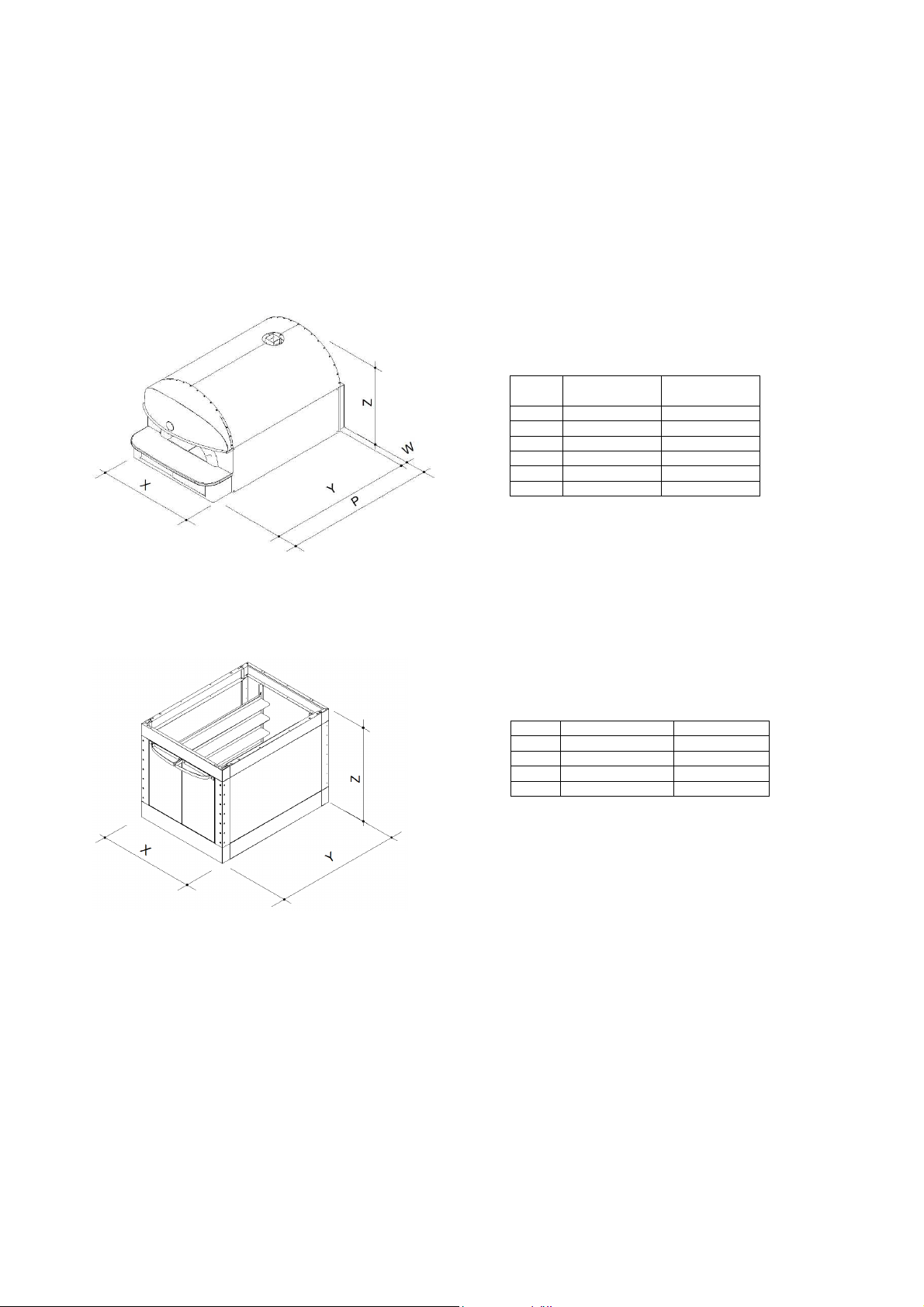
NEAPOLIS
NEAP 6 C NEAP 9 C
X 109 147
Z 94 94
Y 174 179
W 7 7
P 181 186
kg 400 560
NEAP6 L NEAP9 L
X 104 141
Z 105 105
Y 137 137
kg 125 165
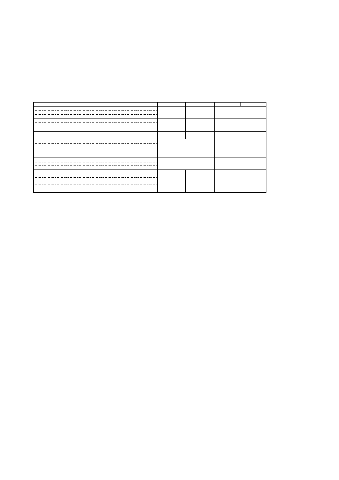
NEAP
C
6P
NEAP
C
9P
NEAP
L
6P
NEAP
L
9P
Potenza Max (kW)
Puissance Max. (kW)
14,35 21,5
1,77 (240VAC)
1,33 (208VAC)
Maximum power (kW)
Höchstleistung (kW)
Potencia máx (kW)
Assorbimento nominale (kWh)
Absorption nominale (kWh)
6,5 6,8
0,89 (240VAC)
0,67 (208VAC)
Rated absorption (kWh)
Soll
-
Stromaufnahme (kWh)
Absorción nominal (kWh)
Ampère (A)
34,9 (240 VAC)
39,9 (208 VAC)
51
,8
(240 VAC)
59,8 (208 VAC)
7,4 (240 VAC)
6,4 (208 VAC)
Tensione nominale (AC)
Tension nominale (C.A.)
240VAC,3ph or 208VAC,3ph 208/240 VAC,1ph
Rated voltage (AC)
Nennspannung
Tensión nominal (AC)
Frequenza
Fréquence
60 Hz 60 Hz
Frequency
Frequenz
Frecuencia
Cavo di allacciamento tipo H07 RN
-
F
/Ampere
Câble de connection type H07 RN
-
F
/Ampere
4x8 AWG 4x6 AWG 3x14 AWG
Connection cable model H07 RN
-
F
/Ampere
Anschlußkabel H07 RN
-
F/Ampere
Cable de conexión tipo H07 RN
-
F
/Ampere
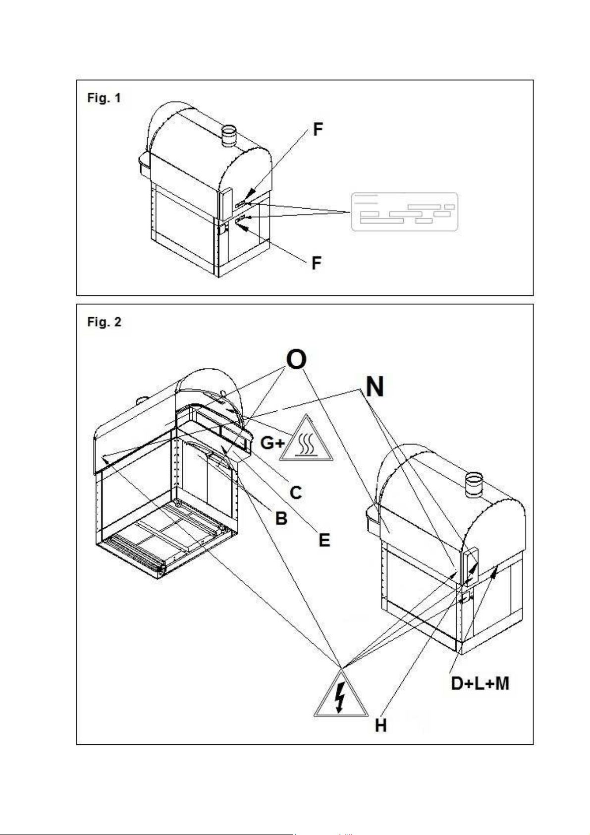
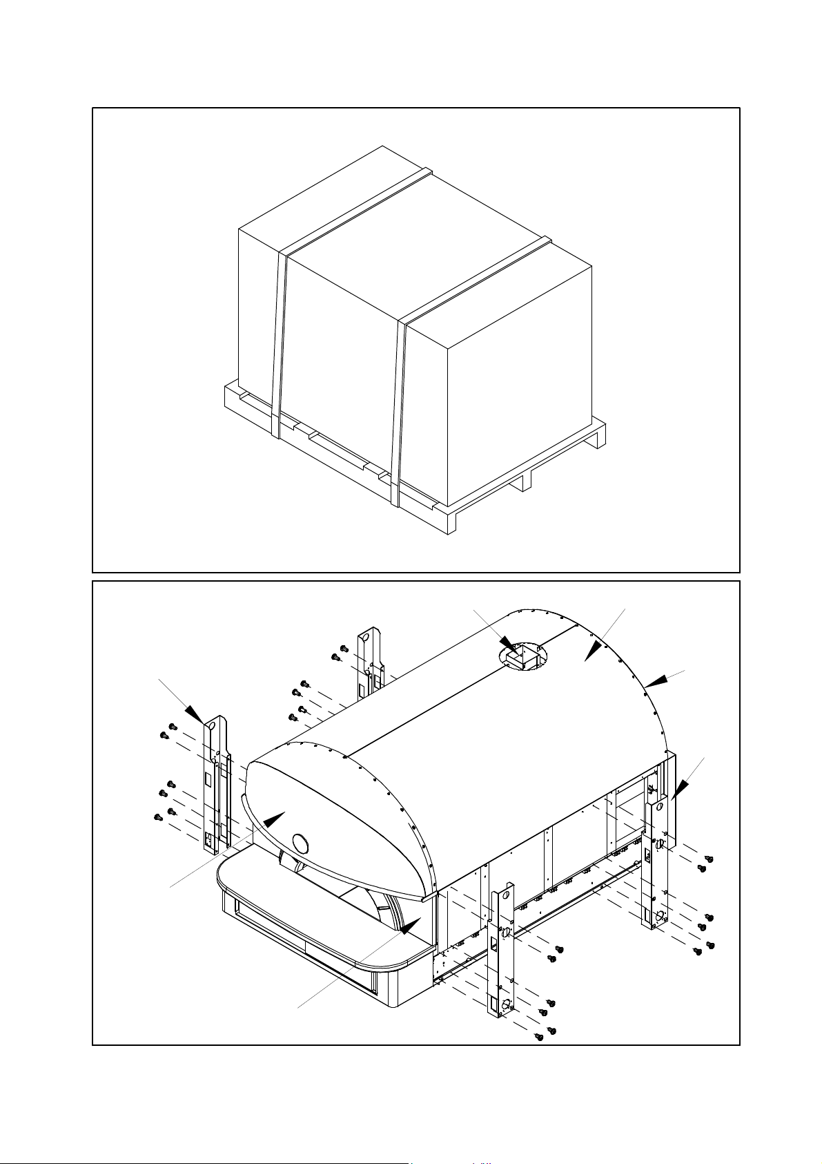
Fig. 3
Fig. 4A
G
F
L
I
H
M
A
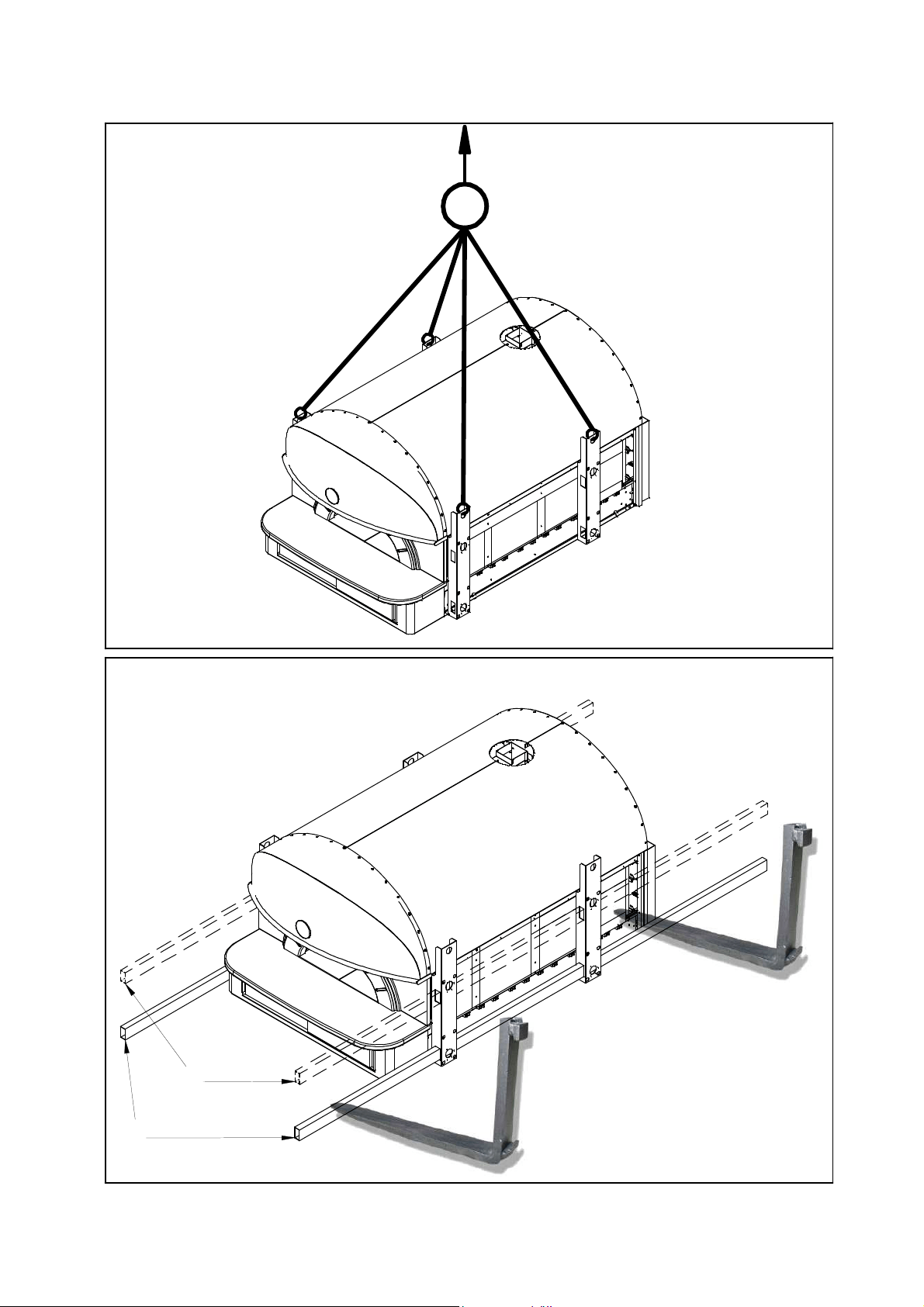
Fig. 4B
Fig. 4C
D
E
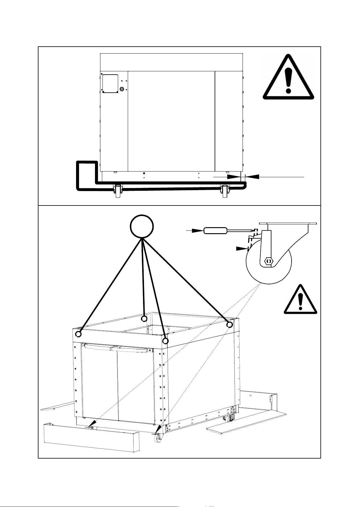
>5cm
(>2")
STOP
GO
Fig. 4D
Fig. 4E
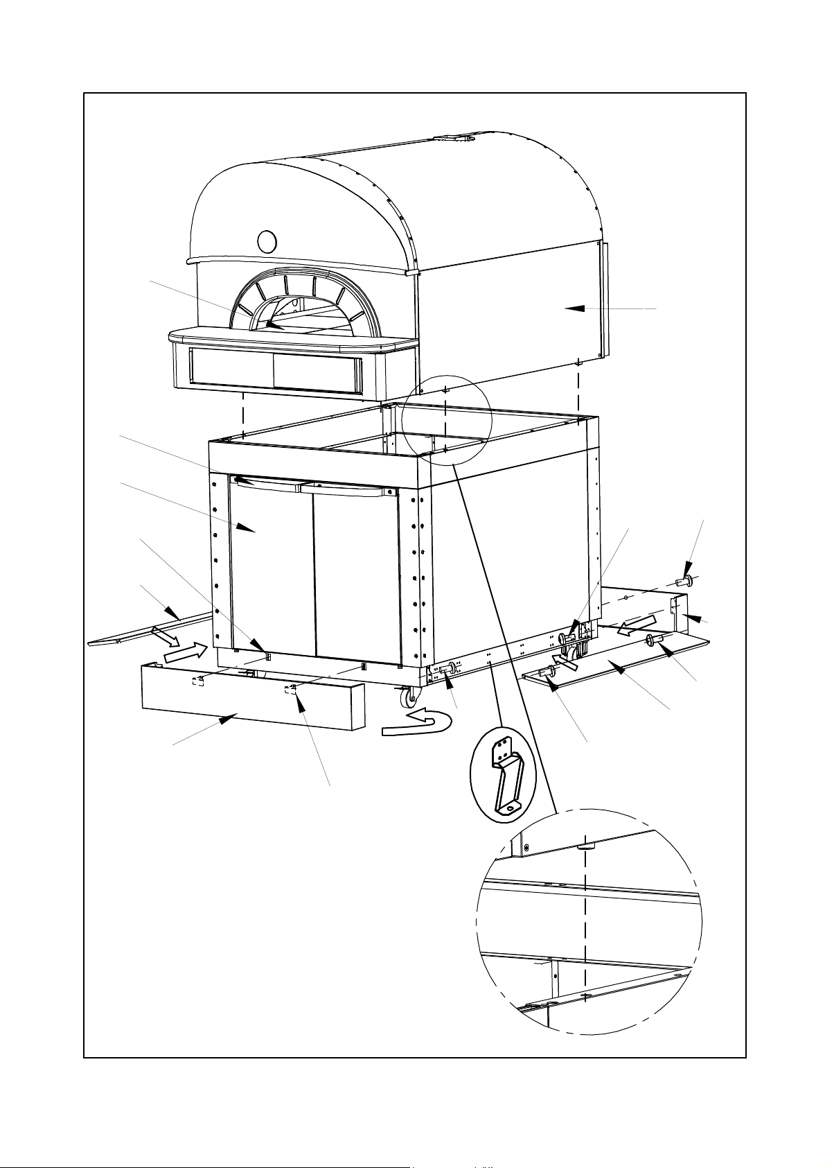
Fig. 5
I
L
M
H
F
G
G
B
F
R
PART. A
C
E
N
P
S
Z
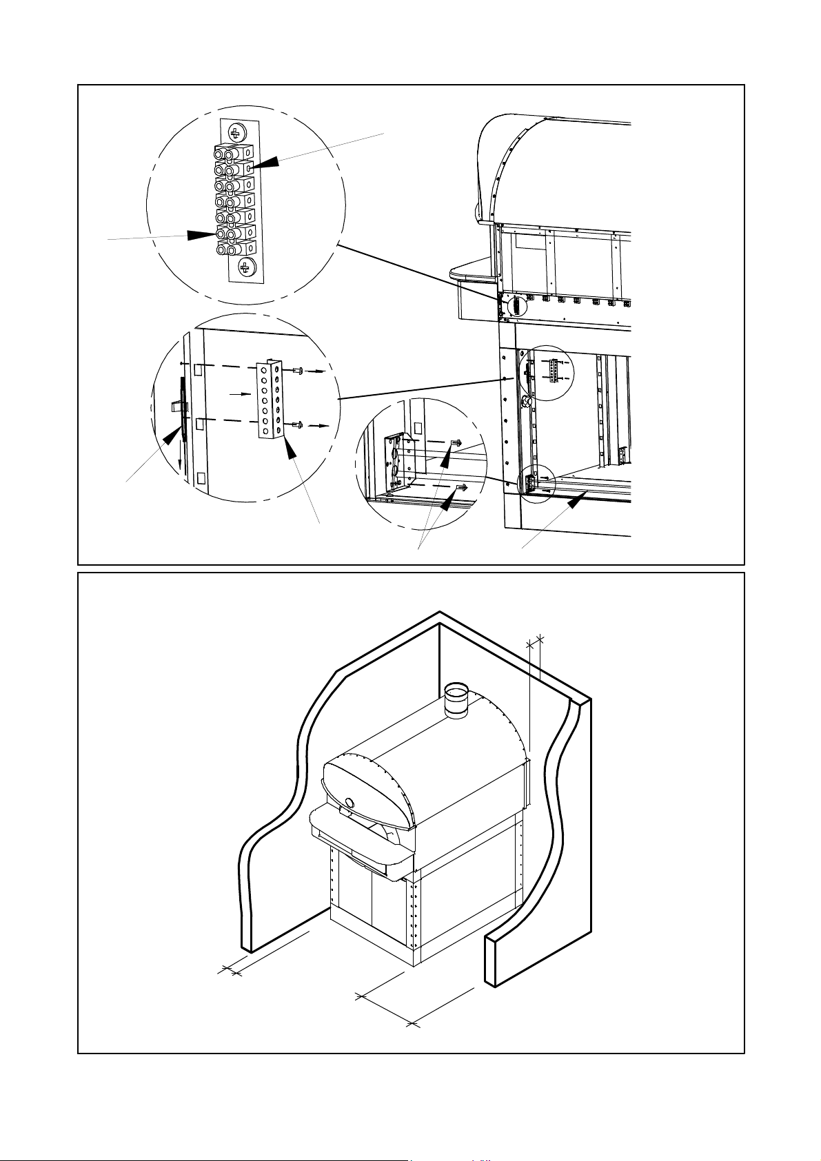
Fig. 6
C
A
B
Fig. 5A
I
L
N
M
P
R
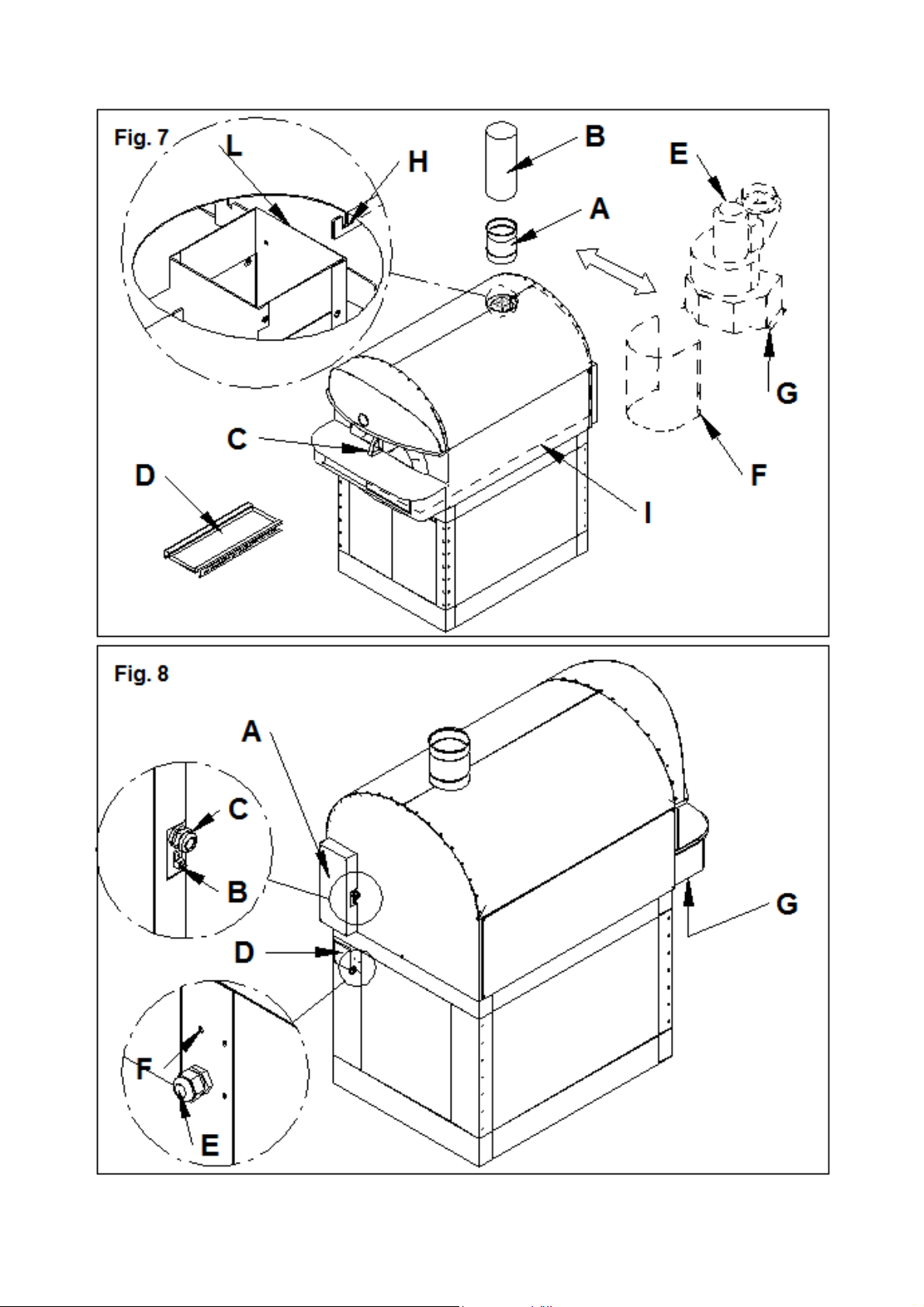
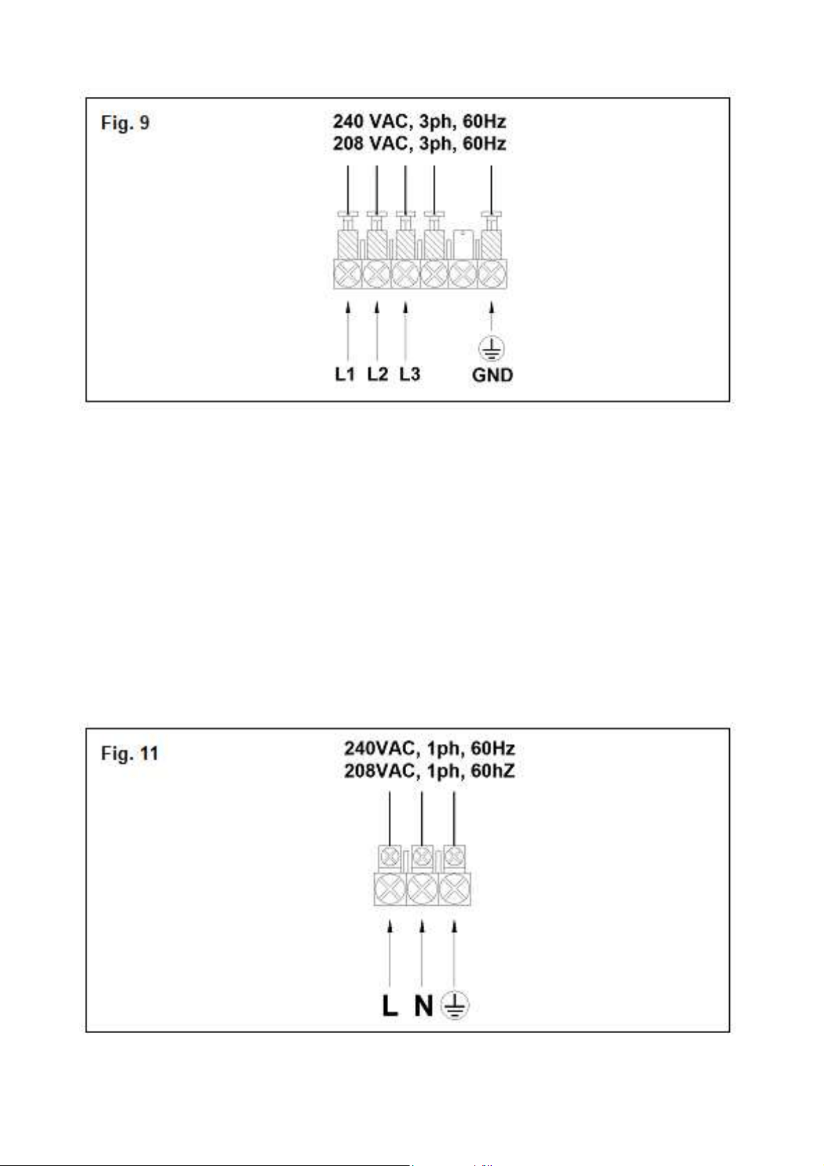
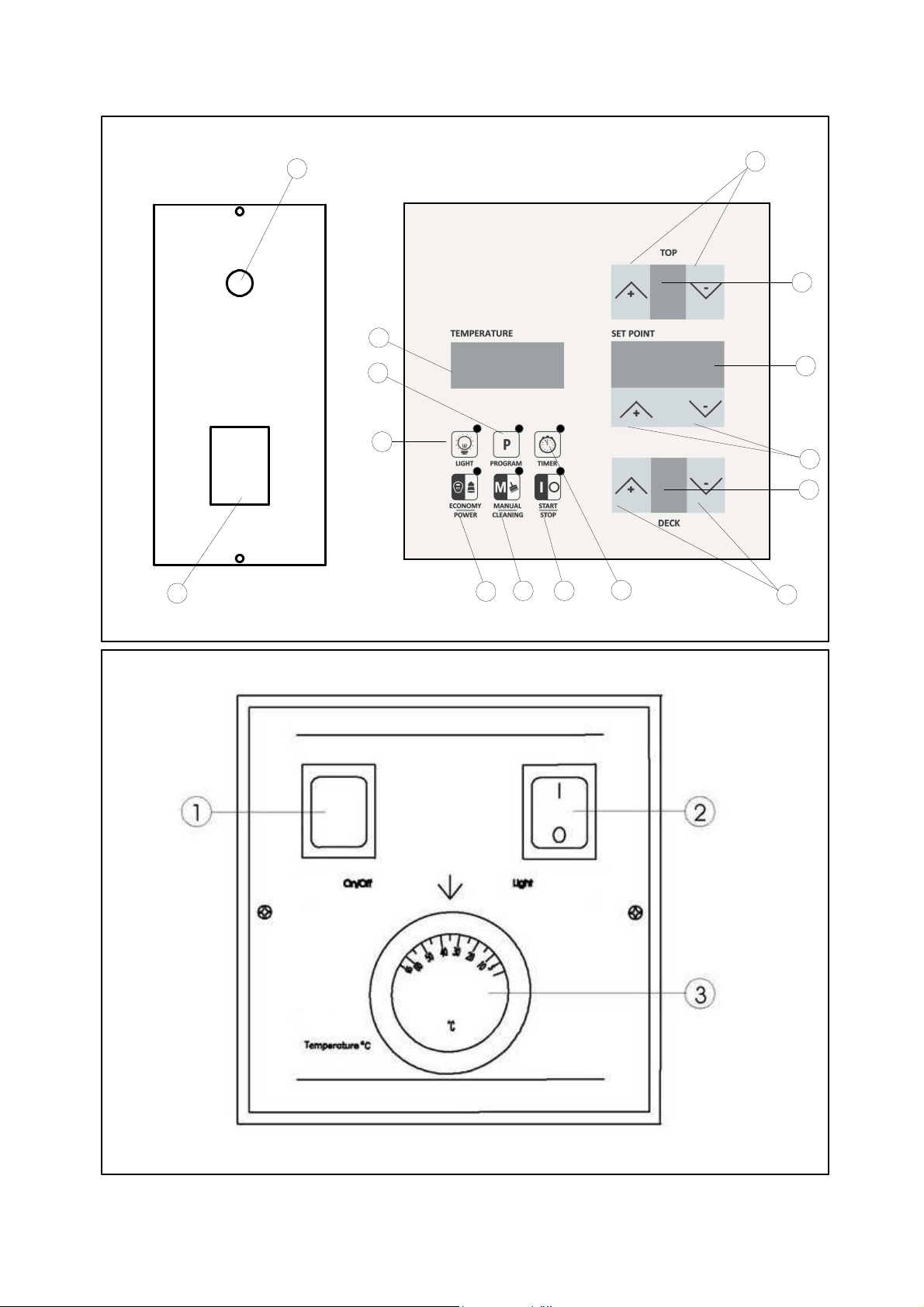
Fig. 12
Fig. 13a
4
6
8
5
7
3
15
913
10
11
12
14
1
2
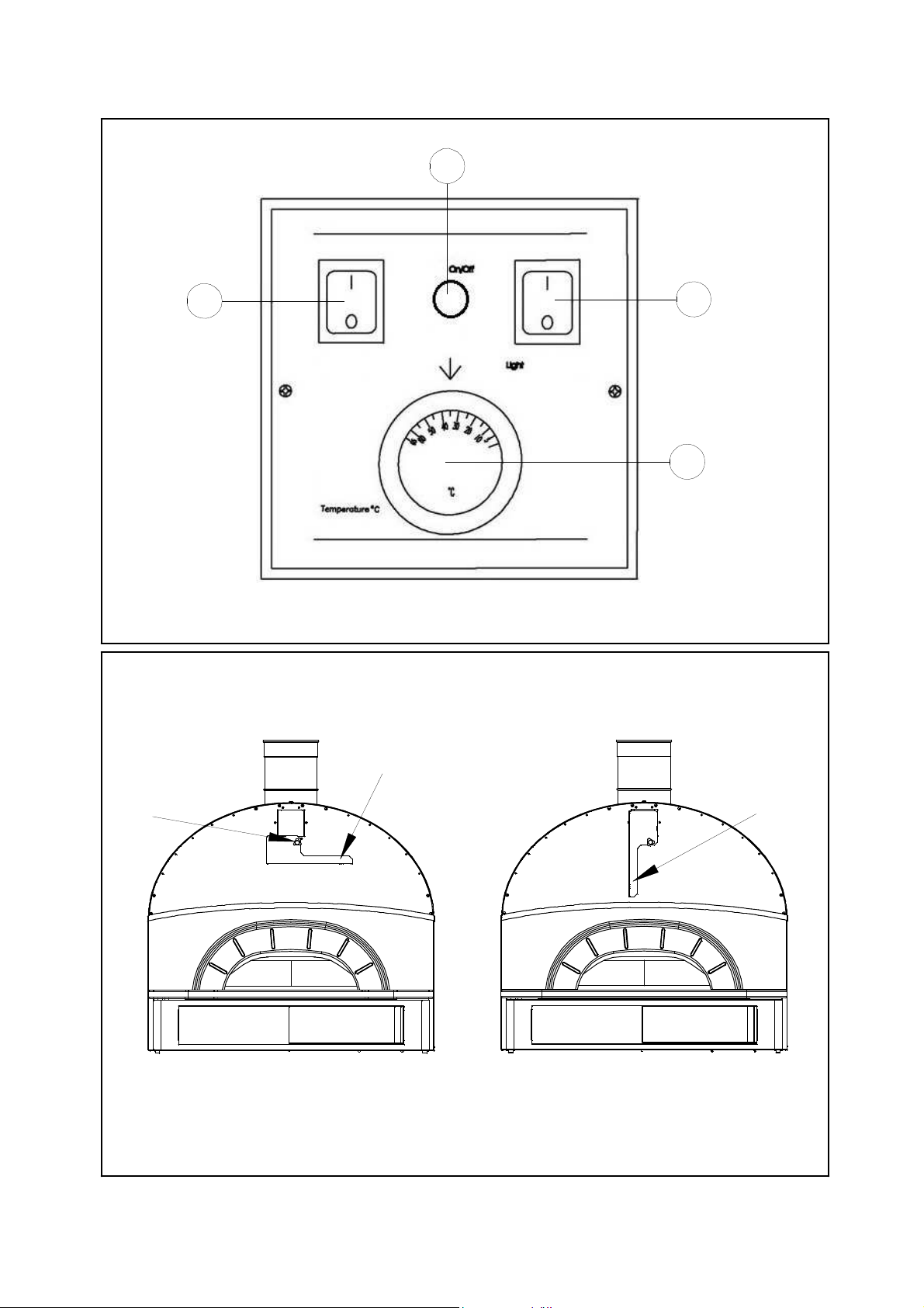
Fig. 13b
Fig. 14
D
O
C
1
2
4
3
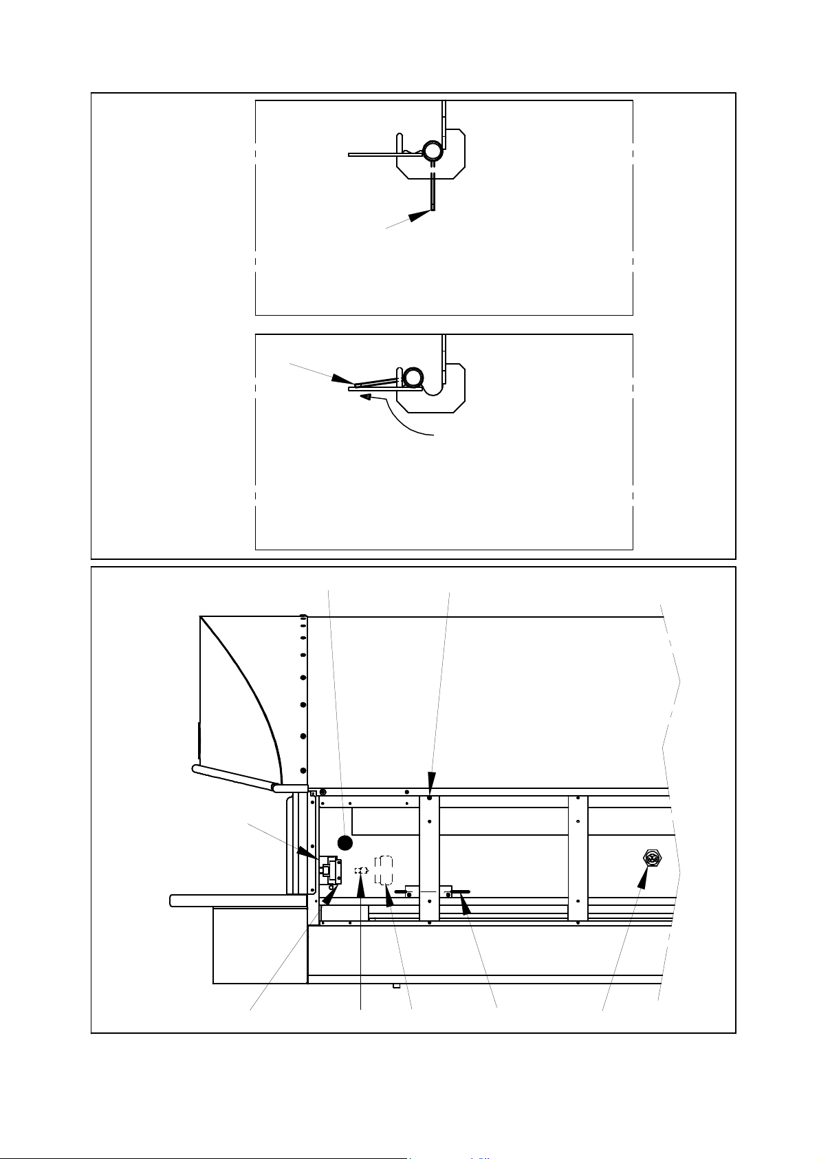
Fig. 15
Fig. 16
A
B
AB
G
C
D
E
F
H
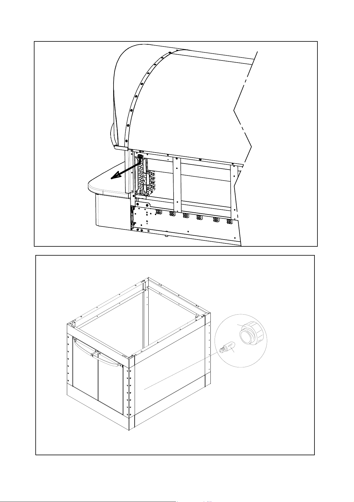
Fig. 16A
F
Fig. 17
A
B

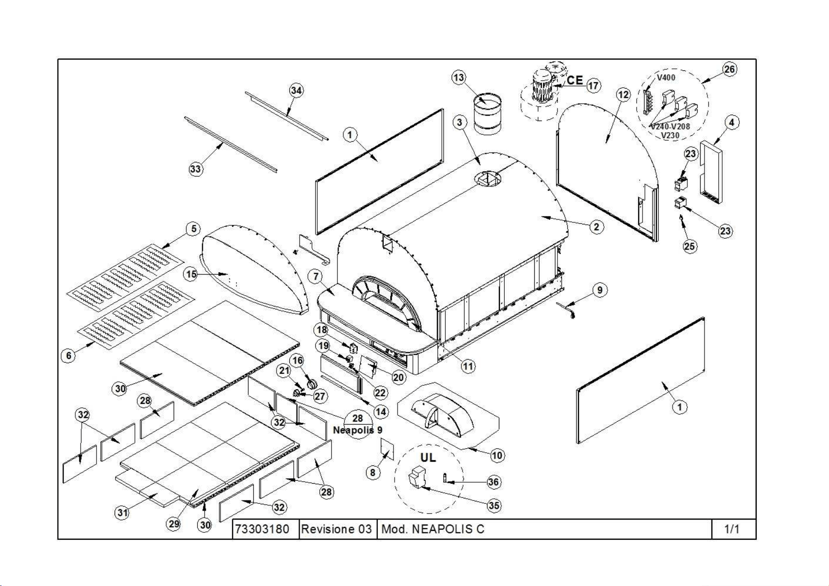
A
Rif. Denomination Designation
1
Panel Panneau
2
Closing panel superior right Panneau de fermeture supérieur droit
3
Closing panel superior left Panneau de fermeture supérieur gauche
4
Panel Panneau
5
Heating Element Résistance
6
Heating Element Résistance
7
Front plane Étage avant
8
Label Etiquette
9
Thermocouple And Clamp Thermocouple Et Borne
10
Door Porte
11
Mouth of the oven Bouche du four
12
External back panel Panneau arrière externe
13
Stainless steel tube D.200 Tube en acier inox D.200
14
Sliding plate Plaque de défilement
15
Hood front Partie frontale hotte
16
Cover Calotte
17
Vapour Exhaust Fan Aspirateur Vapeurs
18
Transformer Transformateur
19
Safety Thermostat Thermostat De Sécurité
20
Power Card Carte De Puissance
21
Bulb Ampoule
22
Switch Interrupteur
23
Contactor Contacteur
25
Suppressor Suppresseur
26
Terminals Board Platine Des Bornes
27
Lamp Holder Douille
28
Side refractory Réfractaire latéral
29
Biscuit for Hob Biscuit pour table de cuisson
30
Bottom and Ceiling refractory Réfractaire du sol et du ciel
31
Biscuit for front hob Biscuit pour table de cuisson avant
32
Side and rear refractory Réfractaire latéral et postérieur
33
Front deflector Déflecteur avant
34
Rear deflector Déflecteur arrière
35
Fuseholder Porte-Fusible
36
Fuse Fusible
73303180 NEAPOLIS C
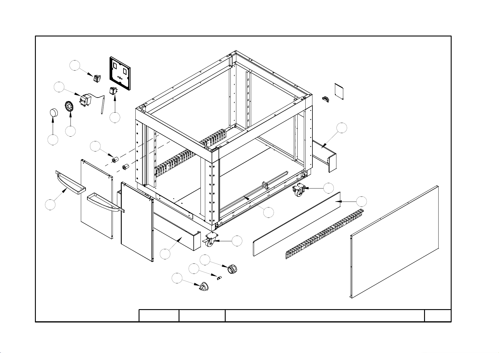
B
73303190
Revisione 02 Mod. NEAPOLIS L
1/1
21
2
8
4
22
5
23
9
16
6
14
7
10
17
18
15
Denomination Designation
2
Handle Poignée
4
Light switch Interrupteur lumière
5
Dial Poignée
6
Ring nut Embout
7
Thermostat Thermostat
8
Bulb Ampoule
9
Lamp holder Douille
10
Heating element Résistance
14
Indicator light Led lumineuse
15
Magnetized pawl Cliquet aimanté
16
Cover Calotte
17
Fixed wheel Roue fixée
18
Swiveling wheel Roue pivotante
21
Front base crosspiece Traverse de base avant
22
Rear base crosspiece Traverse de base arrière
23
Longitudinal side of the base Base latérale longitudinale
73303190 NEAPOLIS L
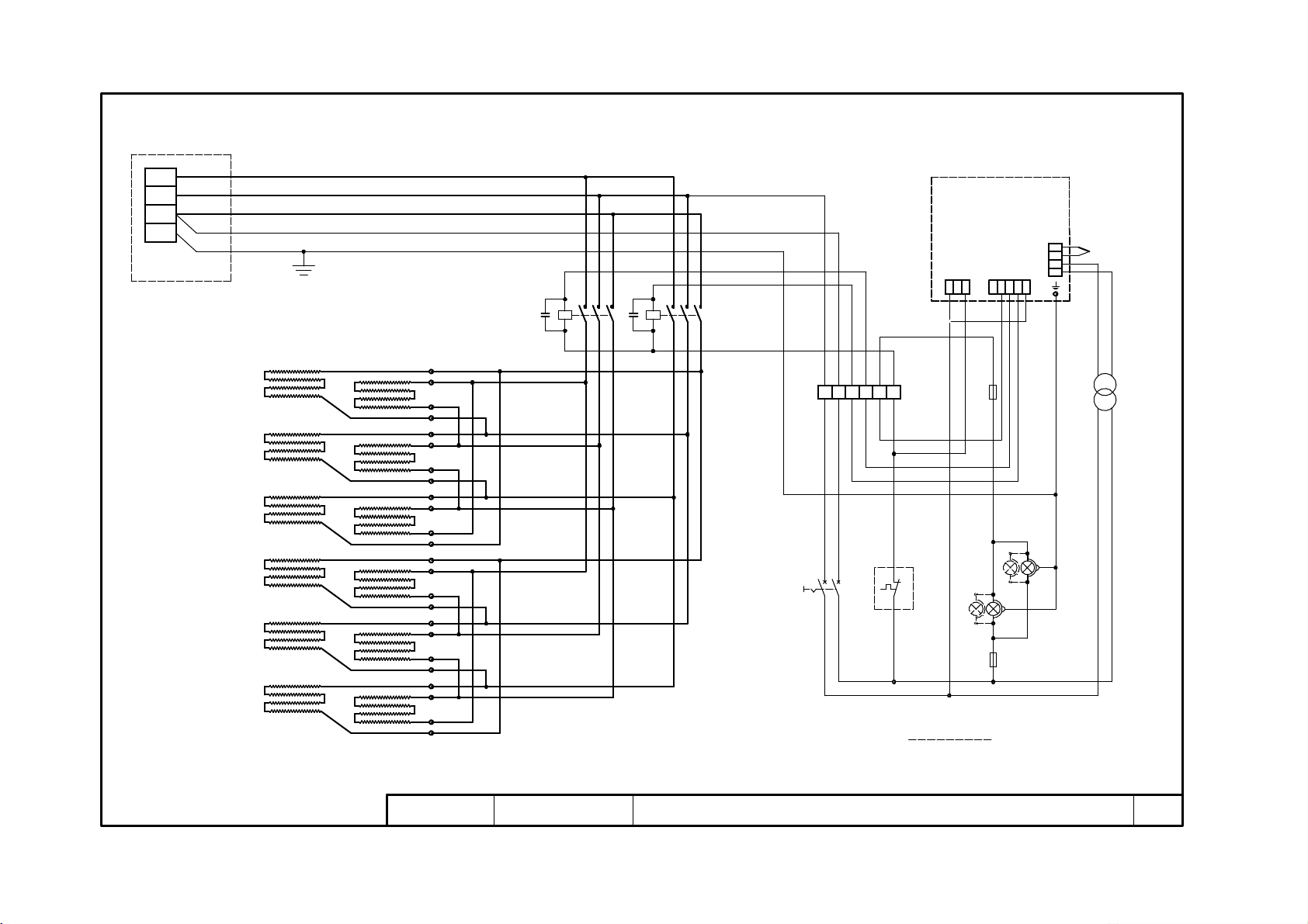
C
74801110
Revisione 00 MOD. NEAPOLIS C V208 3ph V240 3ph 1/1
XP
L1
L3
PE
L2
61
V208 / V240 3ph
A1
A2
64 8
4239 45
1
2
3
60
HLD
26
17
63
73
72
65
HLS
R1
R2
R3
R4
R5
R6
31
48
33
49
37
50
32
51
35
52
38
53
46
42
54
40
55
47
56
44
57
41
58
59
R7
R8
R9
R10
R11
R12
QS
10 11
15
12
18
TS
24
A1
A2
3 51
2 4 6
3 51
2 4 6
3330 36
75 9
C C
X1
KM1
KM2
20
23
19
22
12112 3 98 101
19
14
21
20
SE
TC
3
4
1
2
25
14
12V
+
-
COM
RES.CIELO
RES.PLATEA
LUCE
N.U
ALLARM.
N.U
COM.
10 11 19 20 21
10 11 19 20 21
27
28
13
230V 0V
16
TC
12V 0V
2827
62
.1 .3 .4 .5 .6.2
24
24
17
F1
F2
26
18
21
NEAPOLIS 9P
Rif. Designation Denomination
XP
Mains junction box Entrée réseau
X1
Terminal board Boîte à bornes
R7-12
Ceiling heating elements Résistances ciel
R1-6
Floor heating elements Résistances sole
KM1
Ceiling contactor Contacteur ciel
KM2
Floor contactor Contacteur sole
SE
Pyrometer Pyromètre
TC
Thermocouple Thermocouple
TR
Transformer Transformateur
QS
Main switch Interrupteur alimentation
TS
Safety thermostat Thermostat de securité
HLD-S
Internal lamp Lampe éclairage chambre
F1-2
Fuse Fusible
C1-2
Suppressor Suppresseur
74801110 NEAPOLIS C V208 3ph V240 3ph
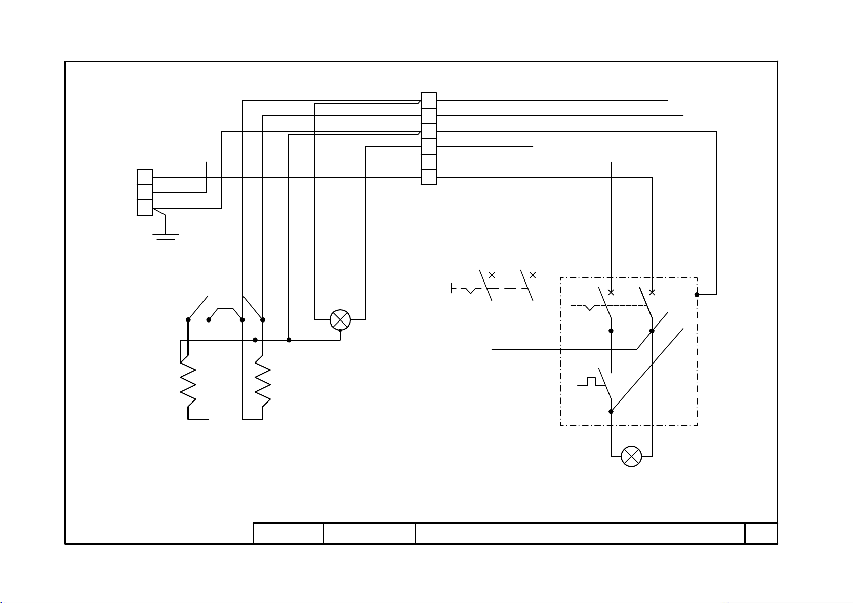
74801120
Revisione 00
MOD. NEAPOLIS L V208/240 1ph 1/1
LC
ILC
V208/240 1ph
6
L2
L1
13
9
10
11
21
RX
18
15
1419
17
1216
STC
TC
8
ITC
7
6
7
3
45
23
20
21
PE
.6
.5
.4
.3
.2
.1
13
17
3
21
7
6
1
13
17
3
21
7
6
X1
XP
C
Rif. Designation Denomination
ILC
Internal light switch Interrupteur lumière chambre
ITC
Thermostat switch Interrupteur thermostat
TC
Thermostat Thermostat
STC
Thermostat light Led du thermostat
LC
Light Lumière
RX
Heating elements Résistances
XP
Mains junction box Entrée réseau
X1
Terminal board Boîte à bornes
74801120 NEAPOLIS L V240 V208