Loading ...
Loading ...
Loading ...
6
STEP 4: VISUAL CHECKS
The following visual check must be performed to ensure that the conversion has been carried out properly and without
damage to other components of the range. Verify that the flame of the oven burner be completely blue and with regular
aspect as shown below.
CONNECTION OF THERMOCOUPLE TO THERMOSTAT
The thermocouple for oven burner is connected to the magnet. Tight gently the connection.
The tip of the spark plug or thermocouple must fully overlap at least the first gas emission hole of the burner.
After performing all these visual checks, reinstall the bottom panel of the oven compartment and proceed to setting the
minimum for each burner.
STEP 5: MINIMUM FLAME ADJUSTMENT
WARNING!
These adjustments should be made only for use of the appliance with Natural gas. For use with ULPG, the choke screw
must be fully turned in a clockwise direction.
Surface burners
Light one burner at a time and set the knob to the MINIMUM position (small flame). Remove the knob.
The range is equipped with a safety valve. Using a small-size slotted screwdriver, locate the choke valve on the valve body
and turn the choke screw to the right or left until the burner flame is adjusted to desired minimum.
Make sure that the flame does not go out when switching quickly from the MAXIMUM to the MINIMUM position.
Oven burner
Set the oven temperature control knob to the MAXIMUM setting. Close the oven door and operate the oven for at least 10
minutes. Set the knob to the MINIMUM setting. Remove the knob. With a slotted screwdriver turn the choking screw (by-
pass screw at the left side of the thermostat bar) and, while observing the flame at the same time through the bottom oven
porthole, evaluate the consistency of the flame so it remains on when switching quickly from MINIMUM to MAXIMUM
setting.
Room Ventilation
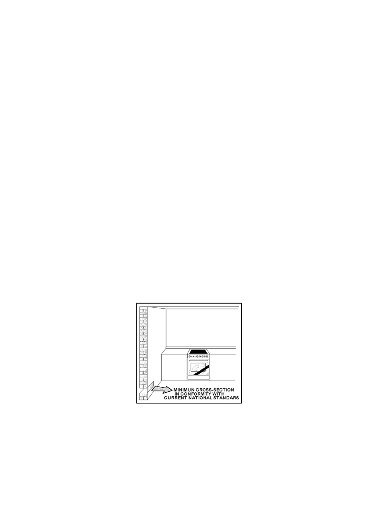
To ensure that the appliance operates correctly, the room where it is installed must be continuously ventilated. The room
volume should not be less than 25m3 and the quantity of air should be based on the regular combustion of gas and on the
ventilation of the room. Natural air will flow through permanent openings in the walls of the room to be ventilated. These
openings will be connected with the outside environment and should have a minimum cross-section defined by current
national standards regarding room ventilation (Fig. 04).
These openings should be built so that they cannot be clogged.
Indirect ventilation is also permitted by taking air from the rooms adjacent to the one to be ventilated.
Fig. 04
Location and Aeration
Gas cooking appliances must always evacuate the combustion products by means of hoods connected to chimneys, flues or
directly outside (Fig. 05). If a hood cannot be installed It is possible to use a fan installed on a window or directly facing
outdoors, to be operated together with the appliance ( Fig. 06), provided that there is strict compliance with the ventilation
regulations.
Loading ...
Loading ...
Loading ...