Loading ...
Loading ...
Loading ...
17
WARNING: Before replacing the bulb, disconnect the appliance from the electric power supply.
WARNING: The power cord supplied with the appliance is connected to the appliance with an X type
connection (in compliance with standards AS/NZS 60335-1, AS/NZS 60335-2-6 and subsequent
amendments) for which it can be installed without the use of special tools, with the same type of cord as the
one installed.
If the power cord becomes worn or damaged, replace it based on the information reported in table 2. To
replace the power cable, lift the terminal board’s cover and replace the cable.
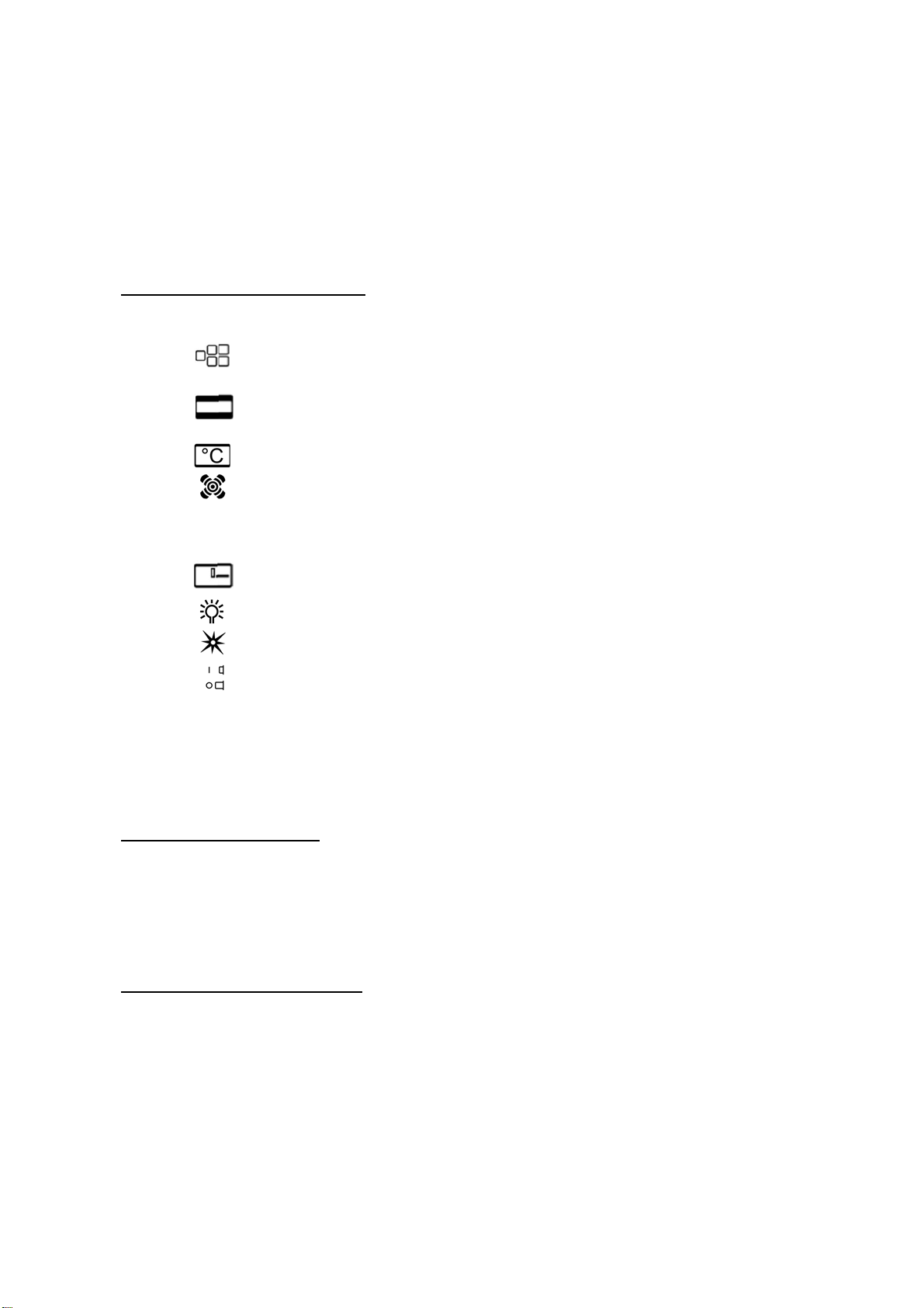
CONTROL PANEL DESCRIPTION
On the control panel, small symbols show the function of each knob or key. Here are the several controls that a
cooker can have:
Indicates which burner on the gas cooktop a control knob controls, a full square
identifying the particular burner.
Indicates the control knob adjusts the functions of the electric oven.
shows the electric thermostat for electric fan oven.
shows the oven fan working button as to allow the oven to operates with fan assisted gas.
The fan operation of the oven prevents the operation of the grill, which therefore cannot be used
with the fan in action.
Indicates the control knob adjusts the mechanical timer
shows the ignition key for the oven light (all except the electric fan oven)
shows the push-button for burner ignition
shows if keys are in position “on” or “off”
WARNING: If the power is cut off, the cook top burners can be lit with matches. When cooking foods
with oil and fat, which are very flammable, the user should not leave the appliance unattended. Do not use
sprays near the appliance when it is being used. When using the burners, make sure that the handles of
the pots are correctly positioned. Keep children away from the appliance.
OVEN RACKS AND TRAYS
The oven is supplied with a baking tray (with removable wire rack) and wire racks.
Internally there is a wire support on either side with 5 mounting positions. The racks and tray are
designed with a small stop at the back. To insert, push the rack into one of the mounting positions
angled down at the front so the stop passes over the front of the support, and then push fully in.
To remove, pull the rack out until the stop catches at the front of the support & angle down to fully
remove.
USING BURNERS ON COOKTOP
A diagram is etched on the control panel above each knob which indicates which burner corresponds to that
knob. Each control knob controls a gas valve and built-in flame safety device.
• Manual lighting (it is always possible even when the power is cut off): Turn the control knob
that corresponds to the burner selected anticlockwise, setting it to the MAXIMUM position at the
etched star (large flame on the control knob (Fig. 18) and hold a lit match to the burner. Press the
knob down and hold for 2 seconds after the burner ignites so the thermocouple heats up. Release
the control knob and adjust to the correct setting.
• Electric ignition: Turn the knob that corresponds to the burner selected anticlockwise, setting it to
the MAXIMUM position (large flame on the control knob (Fig. 18). Keep pressing the knob down at
Loading ...
Loading ...
Loading ...