
Loading ...
Loading ...
Loading ...
Part number 550-100-211/0122
– 57 –
220 /29 9/3 00 /39 9
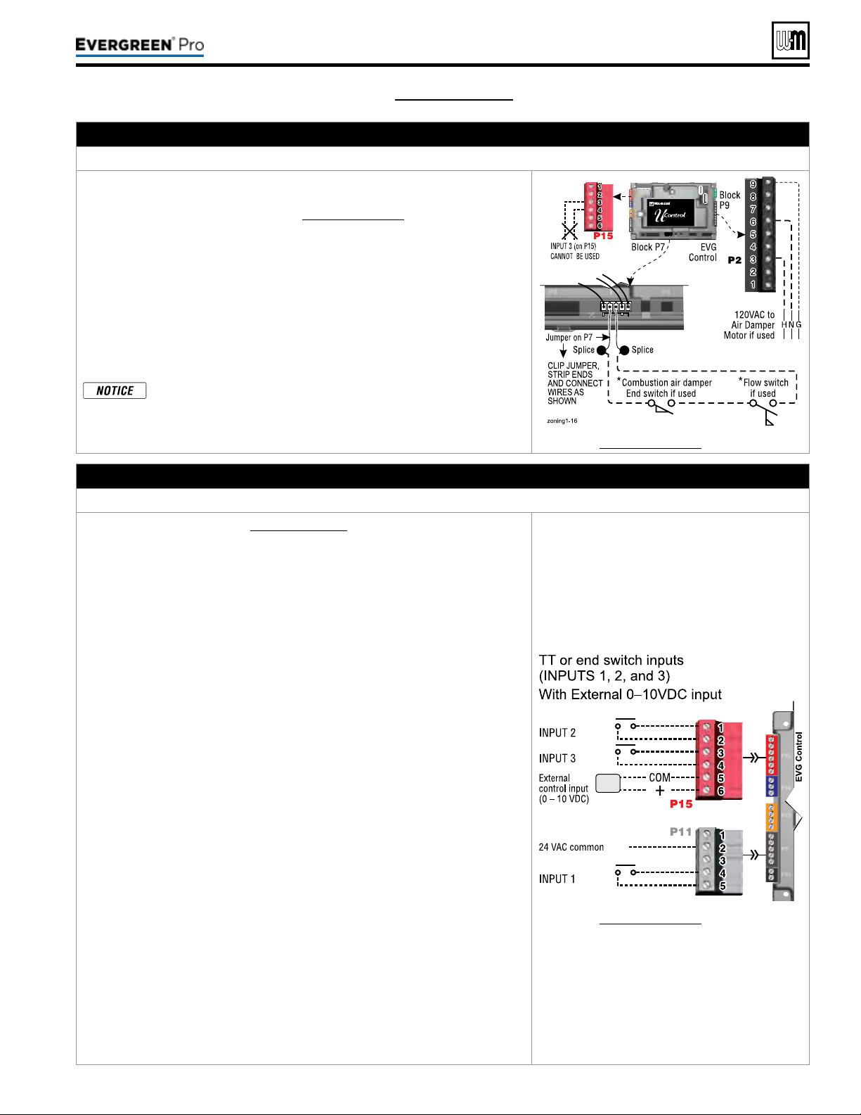
K. Proof of closure (ow switch and/or CAD) – see ADVANCED Manual
– OPTIONAL
JumperonTerminalStripP7(EVG control, bottom left of center)
1. A ow switch or combustion air damper (CAD) interlock can be congured
by clipping the jumper on terminal strip P7 and wiring components as shown
at right and in the wiring diagram (Figure65,page59).
2. No control settings are required when using a ow switch.
3. Recommended conguration of the EVG control for a CAD interlock:
a. Assign INPUT3 as a AUXPUMP/OUTPUT function.
b. For the AUX PUMP/OUTPUT operating mode, select ANY BURNER
DEMAND
. is ensures the damper will be activated any time the boiler
is called on to re.
c. OUTPUT3 will provide 120VAC to the damper motor. Use an isolation
relay if damper motor requires another voltage or more than 2.2 amp if
using 120 VAC.
*
e devices used must provide electrically isolated contacts,
because the P7 jumper circuit carries 5VDC.
See Figure65,page59 for details.
L. 0–10 VDC Remote TARGET input – OPTIONAL
TerminalBlockP15#5(EVG control module, left side)
1. See illustration at right and Figure65,page59 (wiring diagram) for details.
2. Remote target using 0–10VDC input requires a 0–10VDC input signal at P15-4/5
as shown at right.
a. e input positive connection must be at P15 terminal6 and the common
connection at terminal5.
3. is illustration also shows how to connect TT or end switch contacts at INPUT1,
INPUT2 and INPUT3.
a. If a Heat/DHW demand is required, connect the demand’s dry contact to
an unused input on the control and its pump/valve to the respective output.
en assign and setup a priority to the input using the Wizard or manually
through the contractor menu.
b. A dry contact heat demand must be applied to one of the inputs in order to
initiate a call for heat.
4. e 0–10VDC signal is used to adjust the supply target temperature, using the
TARGET ADJUST setting. Set TARGET ADJUST during the WIZARD or
manually in the PRIORITY SETTINGS menu for the desired system/ priority.
a. Many options are available for conguring the control. e following is a
suggested setup that uses factory default settings as much as possible.
b. Use PRIORITY1 for the DHW heating system when used. is priority’s
default values are set for DHW, direct-piped to the boiler. Verify that settings
are suitable for the application, change if needed.
c. Use PRIORITY2 for the heating systems.
y For single boilers, the factory default settings for PRIORITY 2
make this priority a good choice for space heating applications.
Set PRIORITY2 values to the following:
y Set TARGET ADJUST value to 0–10V.
y Set VOLTS FOR MAX at the voltage that will call for the highest target
temperature. Set SUPPLY MAX at this temperature.
y Set VOLTS FOR MIN at the voltage that will call for the lowest target
temperature. Set SUPPLY MIN at this temperature.
y For voltages between VOLTS FOR MAX and VOLTS FOR MIN, the
target temperature will range proportionately between SUPPLY MAX
and SUPPLY MIN. See the EVG Advanced Manual for a full discussion.
y NOTE: e 0–10VDC signal replaces the ODT sensor as the target
temperature modier (TARGET ADJUST setting). e EVG control
does not control target.
See Figure65,page59 for details.
(see wiring diagram, Figure 65, page 59)(continued)
Loading ...
Loading ...
Loading ...