
Loading ...
Loading ...
Loading ...
Part number 550-100-211/0122
– 48 –
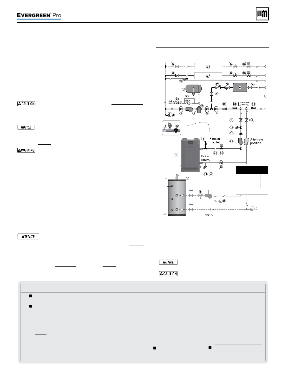
Figure57 Chilled water system plus optional DHW
piping
See Figure57.
1. e chiller must be piped in parallel with the boiler.
2. Use appropriate valves to prevent chilled medium from entering boiler.
3. Circulator zoning option — e space heating system can be zoned with
circulators if a separate circulator is supplied for the chilled water loop.
Install a separate circulator for each zone.
4. e ow/check valve shown on the boiler outlet piping prevents gravity
circulation in the boiler loop during DHW heating.
Use at least the MINIMUM pipe size shown in Figure47,page39 on
all boiler loop piping (connecting boiler to and from the prima-
ry/secondary connection). Use only primary/secondary piping as
shown. Failure to follow these guidelines could result in system
problems.
If antifreeze is used in the system, consider the eects of antifreeze
on circulator sizing and DHW performance. Some local codes
may require double-wall DHW heat exchanger design. Use only
the antifreeze listed by Weil-McLain for use with this boiler. See
page86 for details.
Chilled medium, if used, is piped in parallel with heating boiler
as shown in Figure57. Use appropriate valves to prevent chilled
medium from entering boiler. If boiler is connected to heating
coils located in air handling units where they can be exposed to
refrigerated air, use ow control valves or other automatic means
to prevent gravity circulation during cooling cycle.
Expansion Tank required
1. Provide a system expansion tank following the guidelines on page42.
2. DO NOT use a closed-type tank if connecting to a water heater that is
equipped with an automatic vent.
Domestic Hot Water (DHW) tank, if used
1. DHW direct connection—Pipe from the near-boiler piping to the DHW
tank’s boiler connections as shown.
2. DHW as zone—Not recommended for this application.
3. DHW Priority operation— Using Priority 1 for DHW (default) will
turn o lower priorities during DHW calls. e MAX ON TIME set-
ting can be adjusted to limit how long this occurs. Use Priority 2 or 3
for DHW if DHW priority is not desired.
Overriding the Outdoor Reset function by setting control to
DHW mode when system is intended for space heating may
violate Section 303 of the 2007 Energy Act. See page129 for
compliance information and exemptions.
Controlling the circulators
1. e control can control up to four circulators (boiler circulator and three
others). Refer to Field wiring, beginning on page52, for instructions on
wiring to circulators.
Use isolation relays if connected 3-wire zone valve end
switches to the Heat inputs.
Connect zone valve end switches to Priority2 input.
Connect system circulator to CIRC 2 output.
2. e factory default settings are: all three inputs are setup for
Space Heating (Priority 2). Each input correlates to its respec-
tive circulator output. F
or DHW Priority applications, wire
aquastat to Input 1 and assign to Priority 1.
See Field wiring
instructions, beginning on page52, for details.
3. For more than 3-zones, use Weil-McLain WMZV zone valve
controller.
(continued)
Legend—Figure57
1 Evergreen boiler
2 Indirect water heater, if used
3 Relief valve, supplied with
boiler, eld piped — MUST
be piped to boiler supply
connection — see page41 for
information.
4 Relief valve piping to drain —
see page41.
5 DHW circulator.
6 Isolation valves.
7 System circulator.
9 Air separator.
10 Flow/check valves or spring check.
11 Purge/drain valves (one drain
valve is supplied loose with the
boiler).
12 Boiler circulator.
13 Zone valves.
14 Primary/secondary connection
(tees no more than 12 inches apart)
15 Supplementary expansion tank,
closed type, REQUIRED for
chiller systems (some chiller
systems may use a diaphragm
type expansion tank).
16 Water chiller.
17 Check valve.
18 Y-strainer.
19 Balancing valve.
20 Make-up water supply.
21 By-pass pressure regulator,
RECOMMENDED for zone
valve systems unless other
provision is made.
23 Backow preventer, if used.
25 Pressure reducing valve, if
used.
26
Pressure/temperature gauge,
supplied with boiler, eld piped.
27 Quick-ll valve, if used.
28 Heating circuits.
29 Additional heating circuits, if
any.
31 System supply and return sen-
sors: Strap system sensors to
lines as shown, at least 6 pipe
diameters (but no more than
3 feet) from boiler connection
tees.
32 Low Water Cut-o
= Items supplied with boiler
— all other items supplied by
installer.
220 /29 9/3 00 /39 9
MINIMUM
Boiler loop pipe size
Evergreen 220
Evergreen 299/300,
399
1¼”
1½”
See CAUTION at left.
Loading ...
Loading ...
Loading ...