
Loading ...
Loading ...
Loading ...
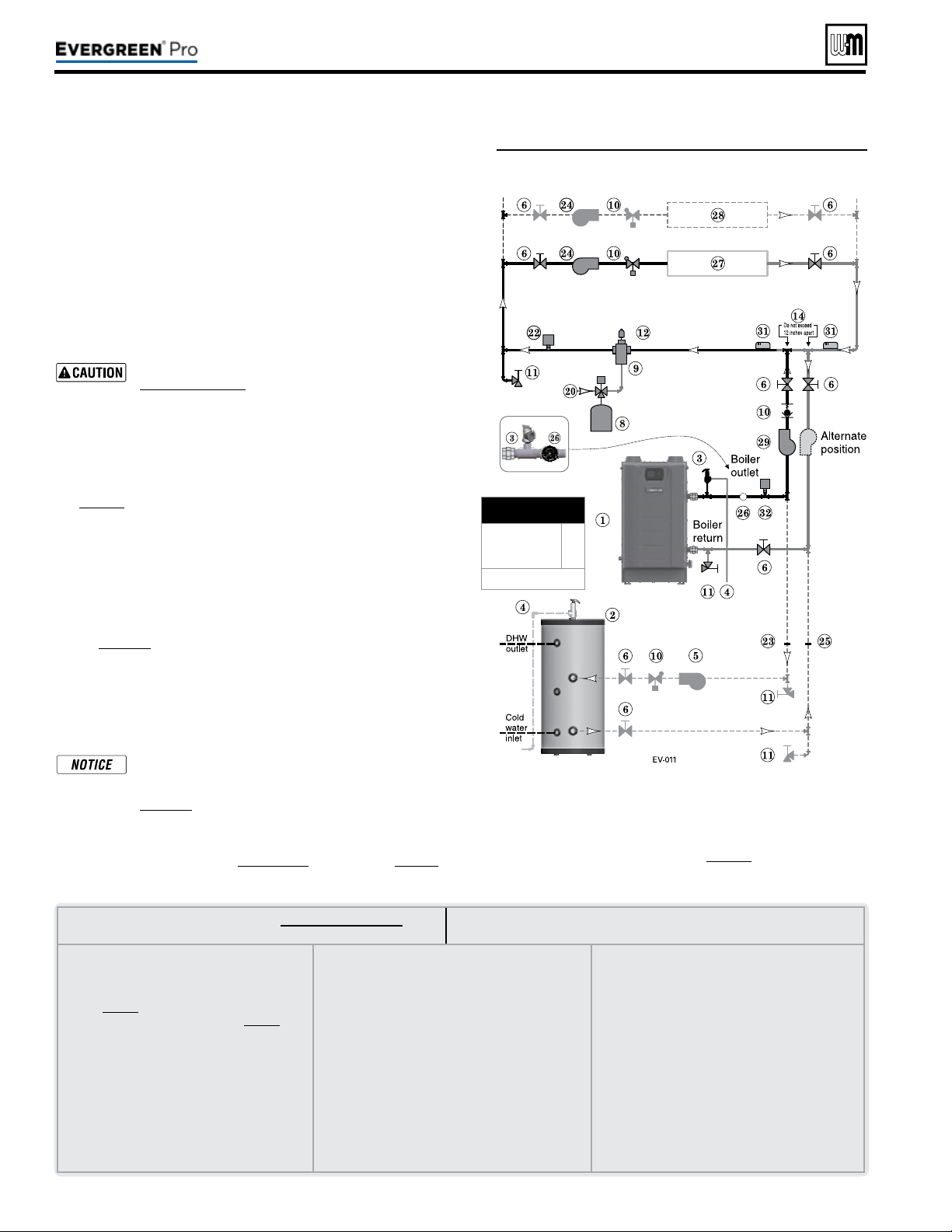
LEGENDforFigure53andFigure54,page45
Note:This is a common legend for all piping diagrams.
Not all items listed appear in every gure.
1 Evergreen boiler
2 Indirect Water Heater, if used
3 Relief valve, supplied with boiler, eld piped —
MUST be piped to boiler supply connection —
see page41 for information
4 Relief valve piping to drain — see page41.
5 DHW circulator
6 Isolation valves
7 System circulator
8 Expansion tank, diaphragm type, if used
9 Air separator
10 Flow/check valves or spring check
11 Purge/drain valves
(one drain valve shipped loose
with boiler)
12 Auto air vent
13 Zone valves
14 Primary/secondary connection (tees no more than
12 inches apart)
15 Expansion tank, closed type, if used (some chiller
systems may use a diaphragm-type expansion tank)
16 Water chiller
17 Check valve
18 Y-strainer
19 Balancing valve
20 Make-up water supply – Use applicable codes to
determine if backow preventers, pressure reducing
valves, and ll valves may be required
21 By-pass pressure regulator,
Recommended for zone
valve systems unless other provision is made
22 High limit temperature control, when required by
local code or for a radiant system.
23 DHW tank boiler water supply connection, when
used
24 Zone circulator
25 DHW tank boiler water return connection, when
used
26 Pressure/temperature gauge, supplied with boiler,
eld piped
27 Heating circuits
28 Additional heating circuits, if any
29 Boiler circulator
30 Mixing device, if any
31 System supply and return sensors: Strap system
sensors to lines as shown, at least 6 pipe diameters
(but no more than 3 feet) from boiler connection
tees.
32
Low Water Cut-o
Part number 550-100-211/0122
– 44 –
See Figure53.
1. is conguration is for circulator-zoned systems using a boiler
loop connected as a secondary circuit o of a primary system
loop. Systems zoned with circulators must pipe the boiler loop as
a secondary circuit as show.
2. Install a separate circulator (supplied by installer) for each zone
capable of delivering the proper ow and head as shown.
3. e ow/check valve shown on the boiler outlet piping prevents
gravity circulation in the boiler loop during DHW heating.
Use at least the MINIMUM pipe size shown in
Figure47,page39 on all boiler loop piping (connecting
boiler to and from the primary/secondary connection,
item14). Useonlyprimary/secondarypipingas
shown. Failure to follow these guidelines could result
in system problems.
Expansion Tank required
1. Provide a system expansion tank following the guidelines on
page42.
2. DO NOT use a closed-type tank if connecting to a water heater
that is equipped with an automatic vent.
Domestic Hot Water (DHW) tank, if used
1. DHW direct connection—Pipe from the near-boiler piping to the
DHW tank’s boiler connections as shown.
2. DHW as zone— A DHW tank can be connected as a zone if a
DHW tank is NOT already connected to the boiler. See notices
on page129 to ensure compliance with the 2007 Energy Act. See
Advanced Manual to congure Boiler Pump to run during DHW
demands and change TARGET MOD SENSOR to System Supply.
3. DHW Priority operation— Using Priority 1 for DHW (default) will
turn o lower priorities during DHW calls. e MAX ON TIME
setting can be adjusted to limit how long this occurs. Use Priority
2 or 3 for DHW if DHW priority is not desired.
Overriding the Outdoor Reset function by setting control
to DHW mode when system is intended for space heat-
ing may violate Section 303 of the 2007 Energy Act. See
page129 for compliance information and exemptions.
Controlling the circulators
1. e control can control up to four circulators (boiler circulator
and three others). Refer to Field wiring, beginning on page52, for
instructions on wiring to circulators.
Figure53 Circulator zoning plus optional DHW piping
2. e factory default settings are: all three inputs are set up
for Space Heating (
Priority 2). Each input correlates to its
respective circulator output. For DHW Priority applications,
wire aquastat to Input 1 and assign to Priority 1. See Field wir-
ing instructions, beginning on page52, for details.
3. For more than 3-zones, use Weil-McLain WMCR zone Circ
controller.
(continued)
220 /29 9/3 00 /39 9
MINIMUM
Boiler loop pipe size
Evergreen 220
Evergreen 299/300,
399
1¼”
1½”
See CAUTION at left.
Loading ...
Loading ...
Loading ...