
Loading ...
Loading ...
Loading ...
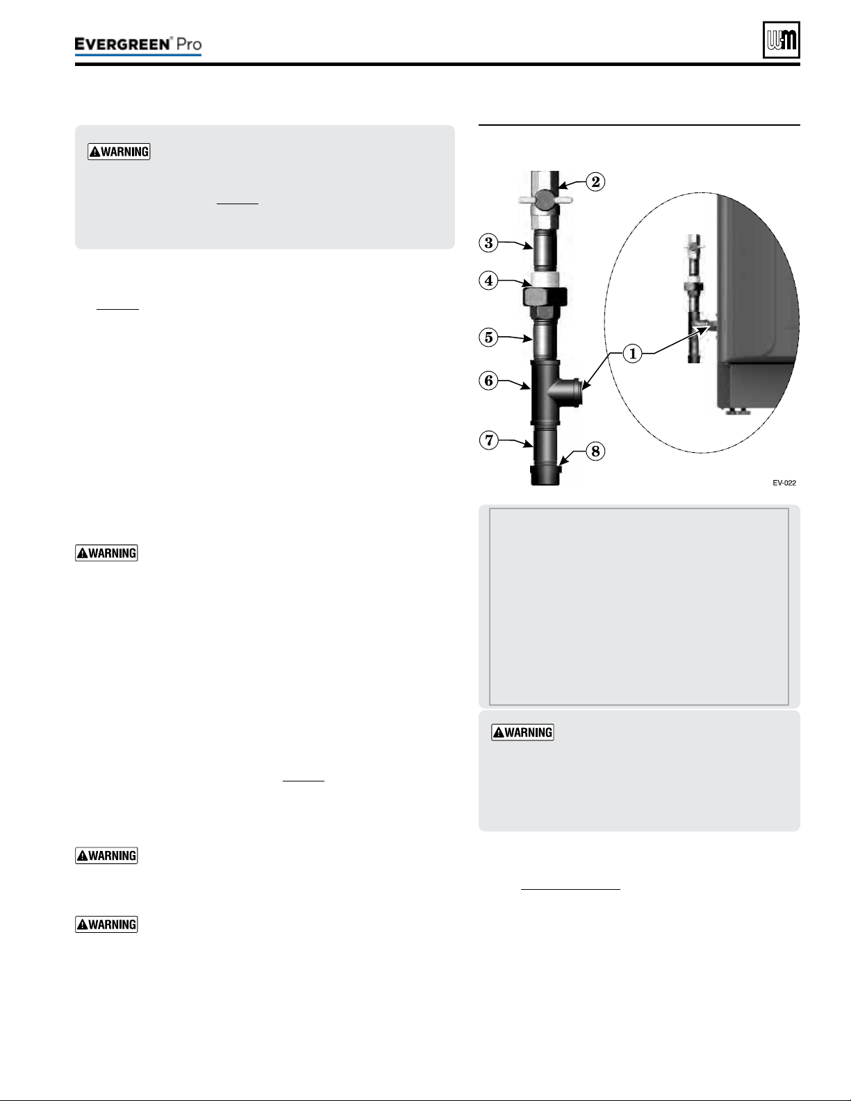
Figure63 Connect gas supply piping
Part number 550-100-211/0122
– 51 –
220 /29 9/3 00 /39 9
1 Boiler gas supply connection, ¾”NPT male.
2 T-handle gas cock, ¾” NPT, shipped loose with
boiler.
ALLOFTHEFOLLOWINGARESUPPLIEDBYTHE
INSTALLER:
3 Nipple, ¾” NPT
4 Union, ¾” NPT
5 Nipple, ¾” NPT
6 Tee, ¾” NPT
7 Nipple, ¾” NPT x 4”, for drip leg
8 Cap, ¾” NPT
Evergreen
®
boilers are shipped ready to fire
natural gas ONLY. You must install the propane
venturi kit if the boiler will be connected to pro-
pane. See page12. Failure to comply could result in
severe personal injury, death or substantial property
damage.
Gaspipesizing
See page18 for gas line sizing information.
1. Refer to Figure63 to pipe gas to boiler.
a. Place a wrench on the gas line when tightening the gas line
assembly to the boiler gas connection (item1).
b. Install steel pipe ttings and factory-supplied gas cock as shown
in Figure63. All pipe ttings are supplied by the installer. e
gas cock is shipped loose with the boiler.
c. In Canada — e gas shut-o valve (item2) must be identied
by the installer.
2. Use pipe dope compatible with propane gases. Apply sparingly
only to male threads of pipe joints so that pipe dope does not
block gas ow.
Failure to apply pipe dope as detailed above can result
in severe personal injury, death or substantial property
damage.
3. Connect gas supply piping to the 3/4” NPT gas cock (item2).
4. Support gas piping with hangers, not by boiler or its accessories.
5. Purge all air from gas supply piping.
6. Before placing boiler in operation, check boiler and its gas con-
nection for leaks.
a. During any pressure testing at less than 14” (356mm) w.c.,
close the gas shuto valve and disconnect system gas piping.
At higher test pressures, disconnect boiler and gas valve from
gas supply piping.
b. Aer placing the boiler in operation, the ignition system safety
shuto device must be tested, page91.
7. Install 100% lockup gas pressure regulator in supply line if inlet
pressure can exceed 14” (356mm) w.c. at any time. Adjust lockup
regulator for 14” (356mm) w.c. maximum.
Do not check for gas leaks with an open ame — use
bubble test. Failure to use bubble test or check for gas
leaks can cause severe personal injury, death or substan-
tial property damage.
DO NOT adjust or attempt to measure gas valve outlet
pressure. e gas valve is factory-set for the correct out-
let pressure. is setting is suitable for natural gas and
propane. Attempting to alter or measure the gas valve
outlet pressure could result in damage to the valve, caus-
ing potential severe personal injury, death or substantial
property damage.
Checkgaspressureatinlettoboiler
1. See Figure88,page91 for location of the gas inlet pres-
sure test port.
2. For natural gas or propane, the pressure required at gas
valve inlet pressure port (verify minimum gas pressure
when all gas appliances are in operation):
a. Maximum: 14” (356mm) w.c. with no ow
(lockup) or with boiler on.
b. Minimum gas pressure, with gas owing (verify
during boiler startup, while boiler is at high re)
3½” (89mm) w.c.
Usetwowrenches when tightening gas
piping at boiler, using one wrench to pre-
vent the boiler gas line connection from
turning. Failure to support the boiler gas
connection pipe to prevent it from turn-
ing could damage gas line components.
Loading ...
Loading ...
Loading ...