
Loading ...
Loading ...
Loading ...
Part number 550-100-211/0122
– 49 –
220 /29 9/3 00 /39 9
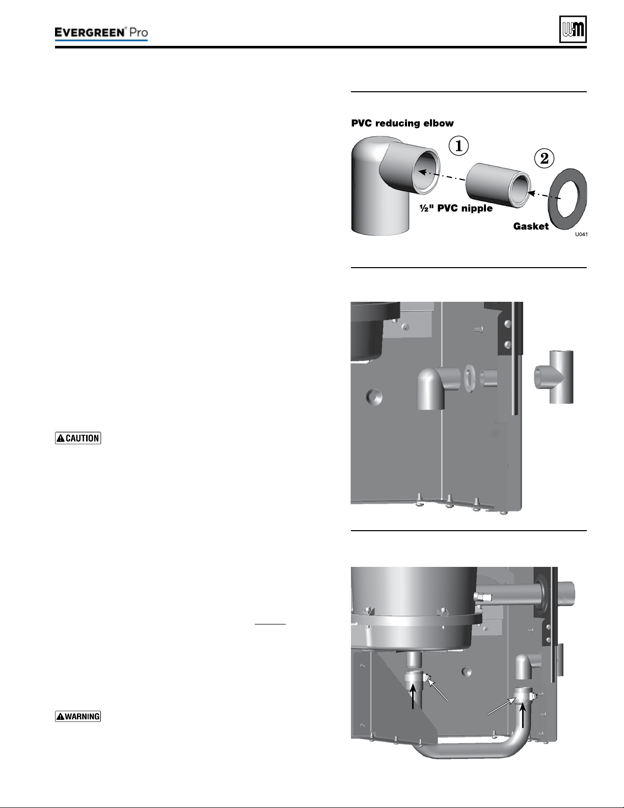
Figure58 Condensate trap assembly
Figure59 Condensate trap assembled into jacket
1. Remove PVC ttings and gasket from the accessories bag.
2. Deburr and chamfer outside and inside of ½” PVC nipple to ensure
even cement distribution when joining.
3. Clean nipple ends and all ttings. Dry thoroughly.
4. For each joint in the condensate line, apply the following.
Assemble parts ONLY in the order given (See Figure58).
a. Apply primer liberally to both joint surfaces — pipe end and
tting socket.
b. While primer is still damp, lightly apply approved cement to
both surfaces in a uniform coating.
c. Apply a second coat of cement to both surfaces. Avoid using
too much cement on sockets to prevent cement buildup inside.
d. With cement still wet, insert pipe into tting, twisting ¼ turn.
Make sure pipe is fully inserted.
e. Wipe excess cement from joint. Check joint to be sure a
smooth bead of cement shows around the entire joint.
5. Assemble the ½” PVC nipple to the PVC reducing elbow as shown.
6. Allow joint to dry completely.
7. en slide gasket over nipple as shown in Figure59.
8. Slide nipple through jacket condensate line hole to position as
shown in Figure59.
9. Cement the ½” tee to the protruding ½” nipple. Be sure both
nipple and reducing elbow nish upright.
Firmly press the reducing elbow and the tee together
while the cement sets to ensure the gasket is securely
compressed. e gasket ensures the jacket enclosure is
airtight at this location.
1. Remove condensate trap line from bag.
2. Connecting condensate line assembly — Figure60:
a. Place a hose clamp over the end of the condensate line.
b. en slide the end of the trap line over the heat exchanger
condensate connection.
c. Tighten the hose clamp to secure the trap line.
d. See “Fill Condensate trap with water” on page88 for proper
instructions on priming the condensate trap, if applicable at
the time.
e. Place a hose clamp over the other end of the condensate trap
line.
f. Slide the trap line over the reducing elbow and secure with
the hose clamp.
Nothing is to be added to top of this tee, Figure59.
Figure60 Condensate drain line connections
Hose
clamps
See
Warning.
Loading ...
Loading ...
Loading ...