
Loading ...
Loading ...
Loading ...
Part number 550-100-211/0122
– 16 –
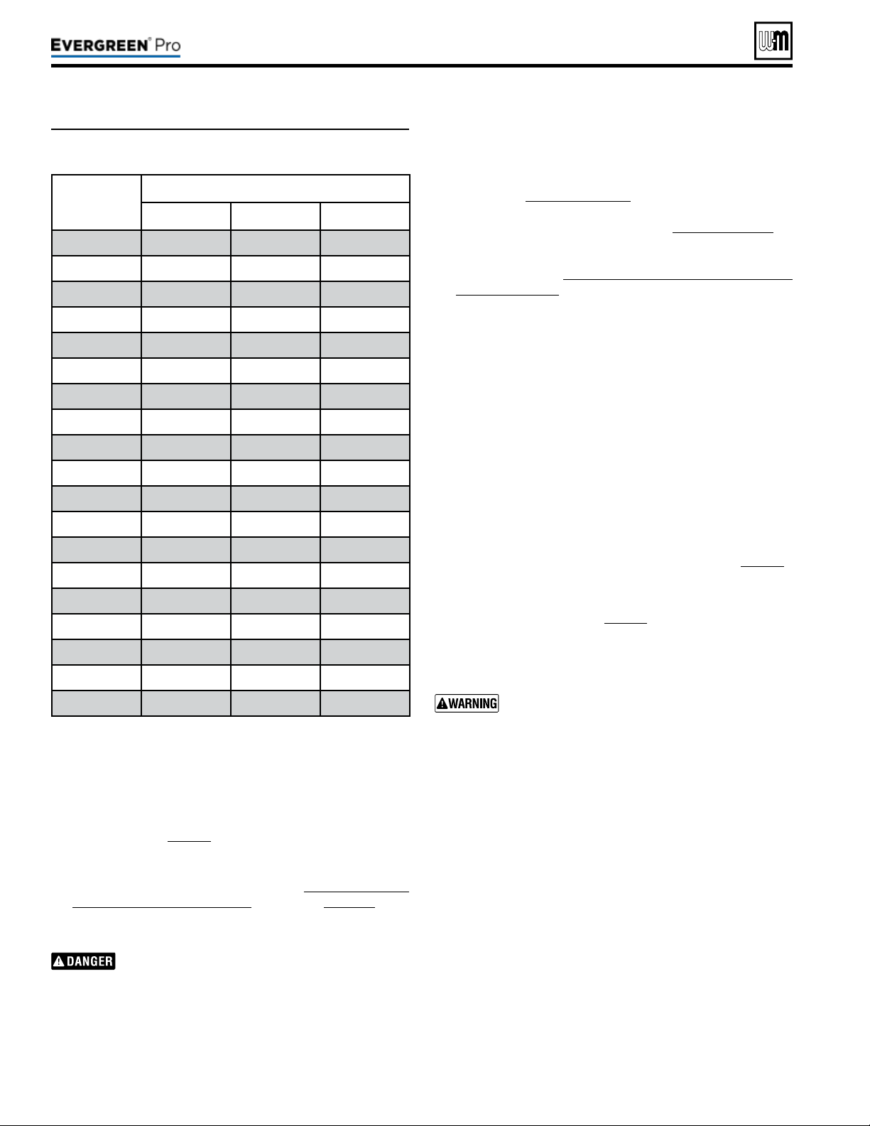
Table2: Low-re blower speeds—Minimum blower speed
settings according to altitude settings.
(continued)
220 /29 9/3 00 /39 9
is set between 96% and 100%. Also verify that the ‘Min
Rate” is set to 10% or the minimum rate allowed (if above
2000 . elevation). Adjust control settings if not at proper
rate. Verify that boiler is operating at the expected ring
rate at both high- and low-re during combustion analysis.
Refer to Table 2, page16 for proper low-re rate based on
altitude settings.
19. Prior to turning on the boiler, review the procedure and
control sequence for the operation of the Manual Test Mode
for Single and Multiple Boilers starting on page101. e
procedure diers between boilers set as a single or multiple-
boiler unit.
e use of a ue gas analyzer is required to convert
this unit and determine proper gas valve settings.
Do not perform this conversion without a ue gas
analyzer. Improper gas valve settings can cause
severe personal injury, death, or property damage.
20. Do NOT allow the boiler to modulate freely until the com-
bustion analysis and adjustment is complete. Turn on and
Altitude
Setting
(ft.)
LowestRateforAltitude
220 299/300 399
0-2000 10% 10% 10%
2500 11% 11% 12%
3000 11% 11% 12%
3500 12% 11% 12%
4000 12% 12% 13%
4500 13% 12% 13%
5000 13% 12% 13%
5500 13% 13% 14%
6000 14% 13% 14%
6500 14% 13% 14%
7000 15% 14% 15%
7500 15% 14% 15%
8000 15% 14% 16%
8500 16% 14% 16%
9000 16% 15% 16%
9500 17% 15% 17%
10000 17% 15% 17%
10500 17% 16% 17%
11000 18% 16% 18%
connect properly working, calibrated combustion analyzer to
the boiler ue pipe. Fire the boiler and force it to High Fire in
Manual Test Mode. Adjust the high re combustion rst, us-
ing the throttle adjustment screw, to the CO2 and CO ranges
specied in Figure89,page91, by model size. en, force
the boiler to Low Fire and adjust the oset regulating screw
to the CO2 and CO ranges specied in Figure89,page91, by
model size. Reinstall the slotted cap over the oset adjustment
screw. Follow the full startup instructions found in this Boiler
Manual including Re-check the Maximum and Minimum
CO2 and CO rate.
21. e coarse adjustment prescribed by this manual should
result in combustion settings that allow for ignition and
are a starting point for further adjustment. If, aer making
the coarse adjustments prescribed above, the boiler will not
light, turn the throttle screw only counterclockwise (Q) an
additional 1/4 turn and attempt to light again. Repeat for a
total of up to one full turn. If, aer following the procedure
above, the boiler still will not ignite or, during combustion
analysis, the analyzer reads less than 1.0% O2, contact Weil-
McLain Technical Services for assistance.
22. Check for gas leaks and conrming proper performance.
Perform complete start-up sequence (beginning on page86),
including check for gas leaks and checking for proper operation.
Aer placing the boiler in operation, the ignition system safety
shuto device must be tested, page91.
Install front door aer servicing. e front door
must be securely fastened to the boiler frame
to prevent boiler from drawing air from inside
the boiler room. is is particularly important if
the boiler is located in the same room as other
appliances. Failure to keep the door securely fastened
could result in severe personal injury or death.
1. Aer installation is complete and boiler is set up for propane
gas, ll out and attach the propane conversion label next to
the boiler rating label (le side of cabinet).
2. Contractor/installer is responsible for completing the in-
formation required on label (provided in kit) and attaching
installer conversion label next to the boiler rating label.
Loading ...
Loading ...
Loading ...