Loading ...
Loading ...
Loading ...
9
SET-UP
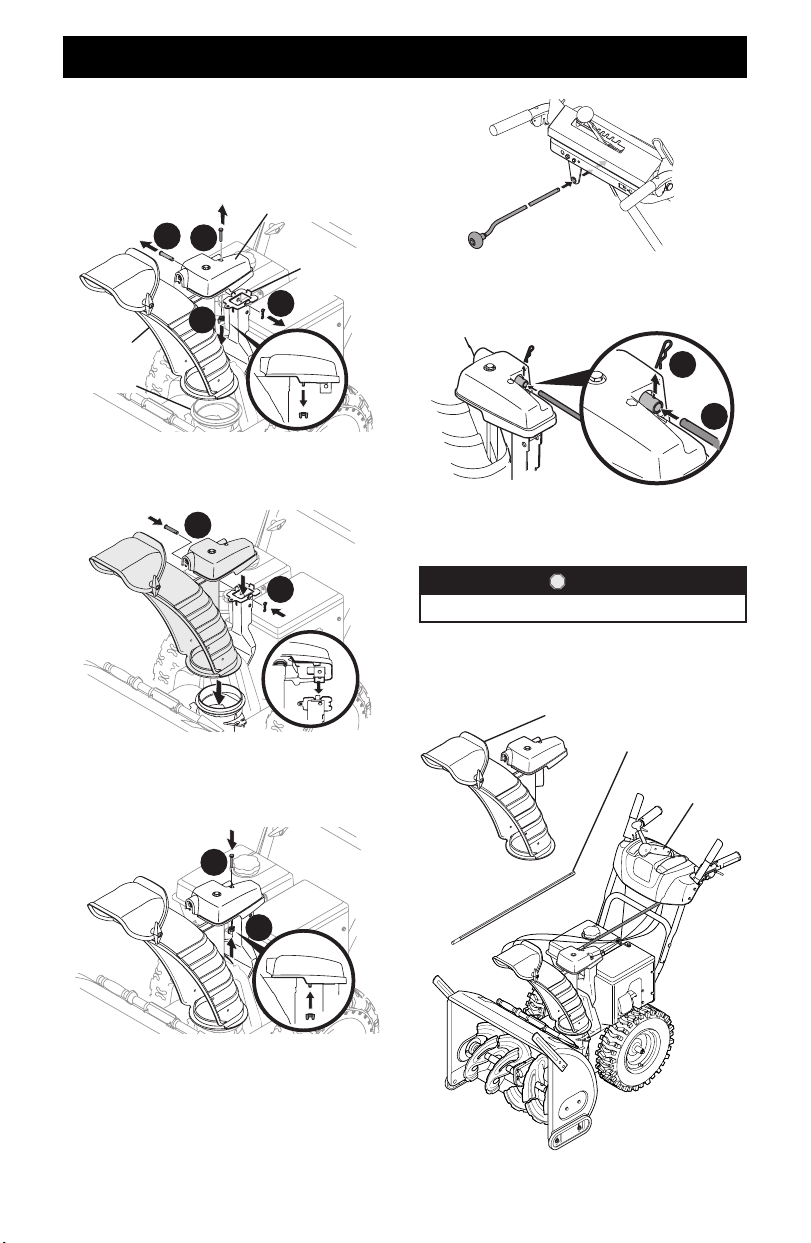
1. Remove wing nut (or locknut if equipped) (a) and hex screw
(b) from chute control head and clevis pin (c) and cotter pin
(d) from chute support bracket. Position chute assembly
(forward-facing) over chute base and chute support bracket
(Figure 13).
Chute Support
Bracket
Chute Control Head
Chute
Assembly
Chute Base
d
a
c
b
Figure 13
2. Secure chute control head to chute support bracket with
clevis pin (c) and cotter pin (d) removed in Step 1 (Figure 14).
c
d
Figure 14
3. Finish securing chute control head to chute support bracket
with wing nut (or locknut if equipped) (a) and hex screw (b)
removed in Step 1 (Figure 15).
b
a
Figure 15
4. Insert chute control rod into the support bracket on rear of
the dash panel (Figure 16).
Figure 16
5. Remove hairpin clip (a) from rear of chute control head
(Figure 17).
a
b
Figure 17
6. Insert chute control rod (b) into rear of chute control head
(Figure 17) and secure with hairpin clip (a) removed in Step 5.
STOP
Continue to Set-Up (page 14).
OVERHEAD CHUTE ROTATION CONTROL W/
2WAY PITCH OR 4WAY PITCH & ROTATION
CONTROL
2 Way/4 Way
Control
Chute Control Rod
Chute Assembly
Figure 18
Loading ...
Loading ...
Loading ...