Loading ...
Loading ...
Loading ...
6
SET-UP
OVERVIEW
• Remove packaging materials from snow blower and any
loose items from the carton.
• Rotate Handle into the upright position. Refer to Handle
Assembly.
• Install the chute. Refer to Chute Assembly Options.
• Complete snow blower assembly according to model and
equipment. Refer to Set-up.
• If necessary make adjustments to ensure proper snow blower
operation. Refer to Adjustments.
• Add fuel and oil. Refer to the Engine Operator’s Manual
shipped with snow blower.
TOOLS REQUIRED
• Adjustable Wrench or Socket Set
• Needle Nose Pliers
HANDLE ASSEMBLY
1. Cut cable ties securing chute control rod or upper handle to
the lower handle (if applicable), set aside the chute control
rod (if applicable) and remove the wrap around the handles
(if applicable).
NOTE: Do not cut the cable tie securing the control cables to
the engine, if equipped.
NOTE: On models with Overhead Chute Control (with Flex
Shaft), Four-Way Chute Control, and Electric Chute Control
cut cable ties securing flex shaft to the lower handle and set
the flex shaft aside. Remove rubber bands securing cables
to carriage bolts and cut cable tie securing shift rod to lower
handle. Refer to Figure 7 to help identify the control styles.
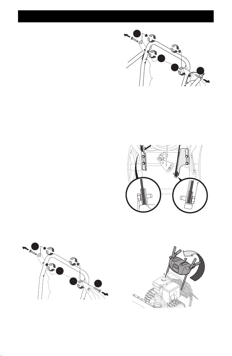
2. Loosen the top two nuts (a) securing the upper and lower handle
and remove the two carriage bolts (b) from the upper handle and
set aside as shown in Figure 1 or Figure 2 for models with side
supports.
a
a
b
b
Figure 1
a
a
b
b
Figure 2
IMPORTANT: Place shift lever in Forward-6 position or fastest
forward speed (if equipped).
3. Observe lower rear area of equipment to be sure both cables
(if equipped) are aligned and seated properly in roller guides
(Figure 3).
NOTE: On select models, chute-pitch control cables will be
routed under the engine on the left side and will not use roller
guides.
Figure 3
4. Ensuring any cables, and wiring harness are clear of pivot
points, Pivot handle upward and align the lower handle
(Figure 4). Remove and discard any rubber bands, if present.
They are for packaging purposes only.
Figure 4
NOTE: On select models with steel rod speed selectors, you
may need to lower shift rod to the side slightly to maneuver
handle panel over it when pivoting handle upward.
Loading ...
Loading ...
Loading ...