Loading ...
Loading ...
Loading ...
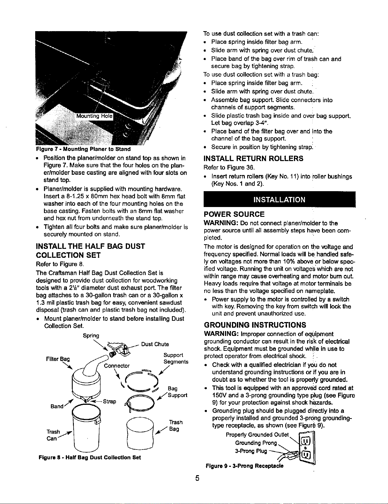
Figure 7 - Mounting Planer to Stand
• Position the planedmolder on stand top as shownin
Figure 7. Make sure that the four holes on the plan-
edmolder base casting are aligned with four slots on
standtop.
• Planer/molder is supplied with mounting hardware.
Insert e 8-1.25 x 80mm he)( head bolt with 8mm fiat
washer into each of the four mounting holes on the
base casting. Fasten bolts with an 8mm fiat washer
and hex nut from underneath the stand top.
• Tighten ell four bolts and make sure planer/molder is
securely mounted on stand.
INSTALL THE HALF BAG DUST
COLLECTION SET
Refer to Figure 8.
The Craftsman Half Bag Dust ConectionSet is
designedto providedust collectionfor woodworking
toolswith a 21/2"diameter dust exhaust port.The filter
bag attaches to a 30-gallon trash can or a 30-gallon x
1.3 milplastictrash bag for easy, convenientsawdust
disposal(trash can and plastictrash bag not included).
• Mount planer/molder to stand beforeinstallingDust
CollectionSet.
Spring
__ DustChute
Support
Filter
J'_- nne r Segments
/' co. /
/s,.port
Figure8 - Half Ba, Dust CollectionSet
To use dust collection set with a trash can:
• Place springinsidefilter bag arm.
• Slide arm with spring over dust chute,
• Place band of the bag over rim of trash can and
secure bag by tightening strap.
To use dust collection set with a trash bag:
• Place spring inside filter bag arm.
• Slide arm with spring over dust chute.
• Assemble bag support. Slide connectors into
channels of support segments.
• Slide plastic trash bag inside and over bag support.
Let bag overlap 3-4".
• Place band of the filter bag over and into the
channel of the bag support.
• Secure in positionbytighteningstrapl
INSTALL RETURN ROLLERS
Refer to Figure 36.
• Insert return rollers(Key No. 11) intomiler bushings
(Key Nos. 1 and 2).
5
POWER SOURCE
WARNING: Do not connect planer/molderto the
powersource untilall assemblysteps have been com-
pleted.
The motoris designedfor operationon the voltageand
frequency specified.Normal loadswillbe handled safe-
lyon voltagesnot morethan 10% above or below spec-
ifiedvoltage. Runningtheuniton voltageswhichare not
withinrange may cause overheatingand motorbum out.
Heavy loads requirethatvoltageat motorterminals be
no less than the voltage specifiedon nameplate.
• Power supply to the motoriscontrolledby a switch
with key.Removingthe key from switchwill lock the
unitand prevent unauthorizeduse.
GROUNDING INSTRUCTIONS
WARNING: Improper connection of equipment
groundingconductor can resultin the risk of electdcal
shock.Equipment mustbe groundedwh!le in use to
protectoperatorfrom electdcal shock. :
• Check with a qualifiedelectricianifyou do not
understandgroundinginstructionsor if you are in
doubt as to whetherthe toolis prope,dygrounded.
• This tool is equippedwith an approvedcord rated at
150V and a 3-pronggroundingtype plug (see Figure
9) for your protectionagainst shockh;_zards.
• Groundingplug shouldbe pluggeddirectly intoa
properly installedand grounded3-prong grounding-
type receptacle, as shown(see Figur_ 9).
PropedyGroundedOutlet\ r_l
GroundingProng,,, Xx'l._ II
3 ProngPlug_O_j I]
Figureg - 3-ProngReceptacle
Loading ...
Loading ...
Loading ...