Loading ...
Loading ...
Loading ...
NOTE: Magnets can beeasily disengaged from blade
by tiltingthem to lefl or right.
CAUTION: Blade edges are extremely sharp. Keep
fingers away from blades at all times.
• Reverse blade or replace with new blade and care-
fully positionit on the two settingringsusing the two
magnets.The setting ringspositionthe blade at the
correctheight.There is one settingring at each end
ofthe cutterhead.
• Retightenchain bysecudng idlerbracket in position.
Tighten sockethead boltssecurely.
• Set planerlmolderback on itsbase.
• Make a test cutto verify adjustment.
Ring
Figure 32 - Use Setting Rings to Position Blades
• Secure blade bytightening the seven gib bolts.Make
sure blade does not move whiletighteningthe bolts.
Use a piece of scrap wood to hold blade in place so
itdoes not creep up.Tighten boltsequally so that
clampingforce is uniformacross blade.
• Depress latch to release cutterhead.Release latch
when cutterbeed can be turned by hand.
• Turn cutterhead by hand untilit is stopped by self-
engaging latch.
• Repeat the above procedurefor the other blade.
• Replace blade cover and secure it usingscrew.
ADJUSTING ROLLERCASE LEVEL
Refer to Figure 33.
The planer/molder willproduce an unevendepth of cut
(tapered cut) ifrollercase is not parallelwith base. To
restore parallelismof rollercasewith base:
• Using a test piece, measure height of the taper.
Determine which corner or side needs adjustment.
• Turn planer/molder off and disconnectfrom power
source.
• Foldfront and rear extension tables.
• Lay planer/molder carefully on itsback so that bot-
tom side of base is facingyou.
• Loosen two socket head boltson the idler bracket.
Loosen chain bysliding idler bracket.
• Carefullyrotate the sprocketbyhandto changethe
rolleroase height.Be sureto leave theother sprockets
untouched.Do not rotate sprocketmore than one or
two teeth. Movementof one sprockettoothrelativeto
the chain movesthe rollercaseapproximately0.006".
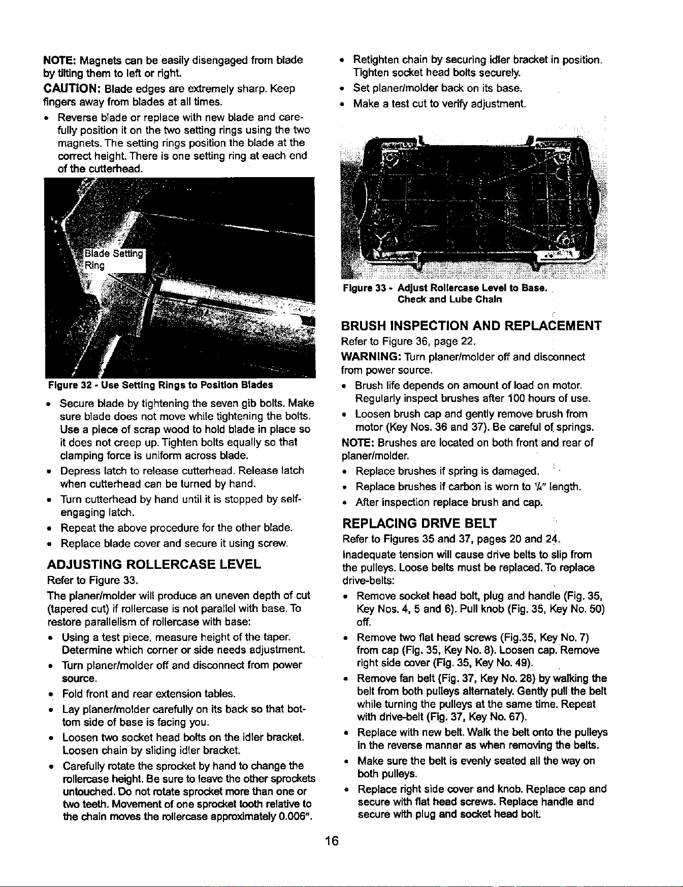
Figure 33 - Adjust Rollercase Level to Base..
Check and Lube Chain
BRUSH INSPECTION AND REPLACEMENT
Refer to Figure36, page 22.
WARNING: Turn planer/molderoffand disconnect
from power source.
• Brushlife depends on amountof load on motor.
Regularlyinspectbrushes after 100 hours of use.
• Loosen brush cap and gently remove brush from
motor (KeyNos. 36 and 37). Be careful o{ springs.
NOTE: Brushes are locatedon both front and rear of
planer/molder.
• Replace brushesif spring is damaged. _
• Replace brushesif carbon is worn to 1/,,length.
• At_erinspectionreplacebrush and cap.
REPLACING DRIVE BELT
Refer to Figures35 and 37, pages 20 and 24.
inadequate tension willcause drive beltsto slipfrom
the pulleys.Loose belts must be replaced.To replace
drive-belts:
• Remove sockethead bolt, plug and handle (Fig. 35,
Key Nos.4, 5 and 6). Pull knob (Fig.35, KeyNo. 50)
off.
• Remove two fiat head screws(Fig.35, Key No.7)
from cap (Fig. 35, Key No. 8). Loosen cap. Remove
rightside cover (Fig. 35, Key No.49).
• Remove fan belt (Fig. 37, Key No.28) byWalkingthe
belt from both pulleysalternately.Gently pullthe belt
whileturningthe pulleysat the same time. Repeat
with drive-belt(Fig. 37, Key No. 67).
• Replacewith new belt.Walk the belt onto the pulleys
in the reverse manner as when removingthe belts.
• Make sure the belt is evenly seated all the way on
bothpulleys.
• Replace rightside cover and knob. Replace cap and
secure withfiat head screws. Replace handle and
secure with plug end socket head bolt.
16
Loading ...
Loading ...
Loading ...