Loading ...
Loading ...
• Handle workpiece correctly.Protect handsfrom
possibleinjury.
• Turn machine off if itjams. Bladejams when it digs
too deeply intoworkpiece. (Motor force keeps it
stuck in the work.)
• Always keep drive, cutterhead and blade guards in
place and in proper operating condition.
• Feed work into blade or cutter againstdirectionof
rotation.
CAUTION: Think safety! Safety isa combination of
operator common sense and alertness at alltimes
when tool is being used.
WARNING: Do not attemptto operate tool untilit is
completely assembled accordingto the instructions.
Refer to Figures 1 and 2.
Check for shippingdamage. If damage has occurred,a
claim must be filedwith carder. Check for complete-
ness. Immediately report missingparts to dealer.
The planer/molder comes assembledas one unit.
Additional parts which need to be fastened to
planer/molder shouldbe locatedand accounted for
beforeassembling.
A. Handle Assembly
B. 5-0.8 x 25mm Socket Head Bolt
C. Plug
D. Roller Height AdjustmentWrench
E. Dust Chute
F. 6-1.0 x 25mm Socket Pan Head Screw
G. Roller (2)
H. Molding Gib and Spacer Set (4)
Not Shown:
Half Bag Dust Collection Set
Auxiliary Table Hardware Bag (Part No. 21012.00)
includes:
• #10-32 x 23/d' Socket Head Bolt(2)
• #10 FlatWasher (2)
• Clamp (2)
• 1/,-20x 11/," Wing Screw (4)
• 1/4"Flat Washer (4)
• Table Insert (4)
Figure1 - UnpackingPlaner/Molder
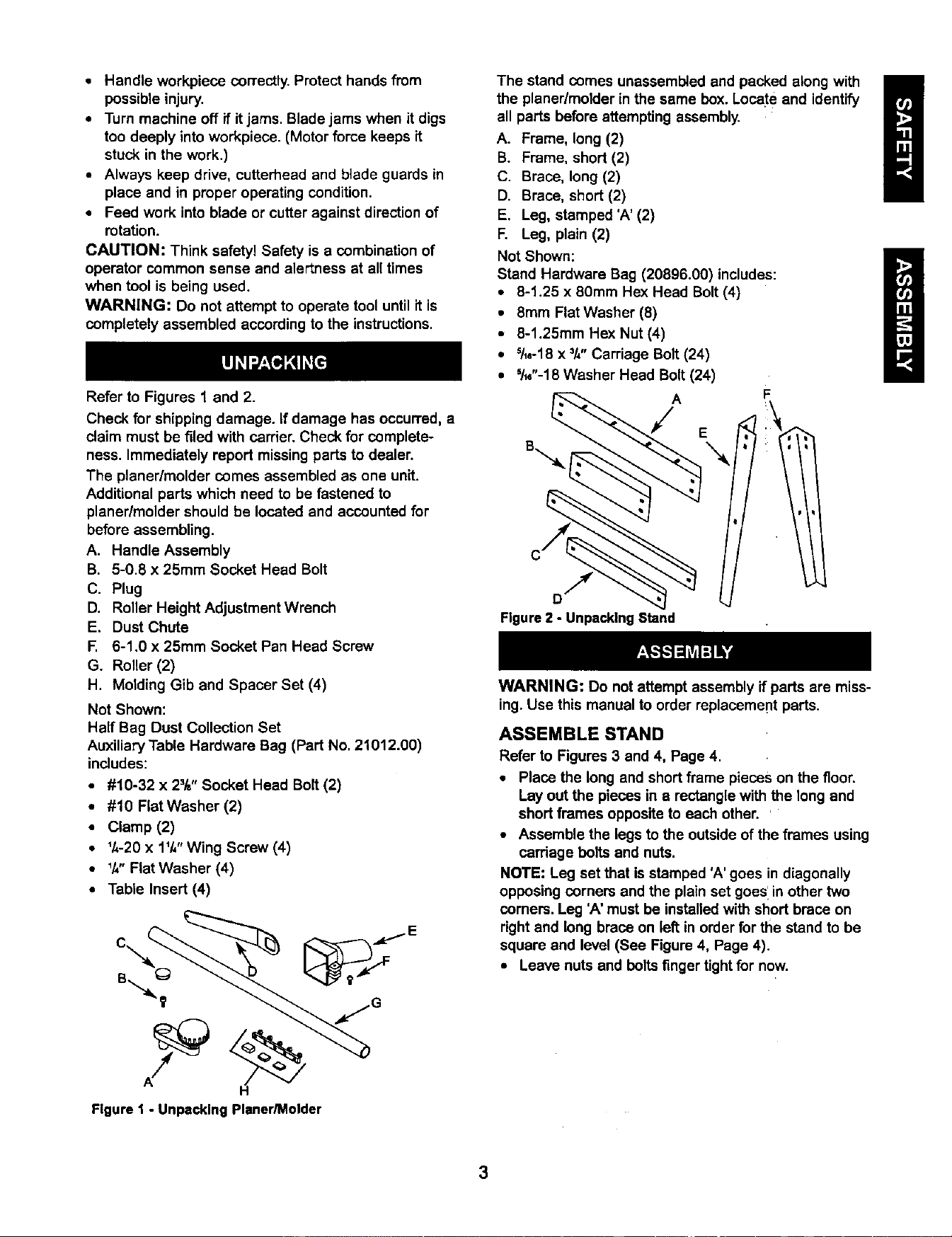
The stand comes unassemb_edand packed along with
the planer/molderin the same box.Locate and identify
all parts beforeattemptingassembly.
A. Frame, long (2)
B. Frame, short (2)
C. Brace, long (2)
D. Brace, short(2)
E. Leg, stamped 'A' (2)
F. Leg, plain (2)
Not Shown:
Stand Hardware Bag (20896.00) includes:
• 8-1.25 x 80ram Hex Head Bolt(4)
• 8mm Flat Washer (8)
• 8-1.25mm Hex Nut (4)
• S/le-18 X =/4" Carriage Bolt(24)
• 51_e"-18Washer Head Bolt(24)
A
E
F
Figure 2 - Unpacking Stand
WARNING: Do not attemptassembly ifparts are miss-
ing. Use this manual to order replacement parts.
ASSEMBLE STAND
Refer to Figures3 and 4, Page 4.
• Place the long and shortframe pieces on the floor.
Layout the pieces in a rectanglewiththe long and
shortframes oppositeto each other. '
• Assemble the legs to the outsideof the frames using
cardage boltsand nuts.
NOTE: Leg set that isstamped 'A' goes in diagonally
opposingcorners and the plainset goes'inother two
corners. Leg 'A'must be installedwith short brace on
rightand long brace on left in order for the stand to be
square and level(See Figure4, Page 4).
• Leave nuts and bolts finger tightfor now.
3
Loading ...
Loading ...
Loading ...