Loading ...
Loading ...
Loading ...
GUIDE FENCES
When molding,the workpiece mustbe guided intothe
molding cutter bits or knives properlyin order to pro-
duce the desired shape and size molding.Usingprop-
edy adjusted guide fences assures the workpiecepass-
es the molding cutters/knivesin the same position
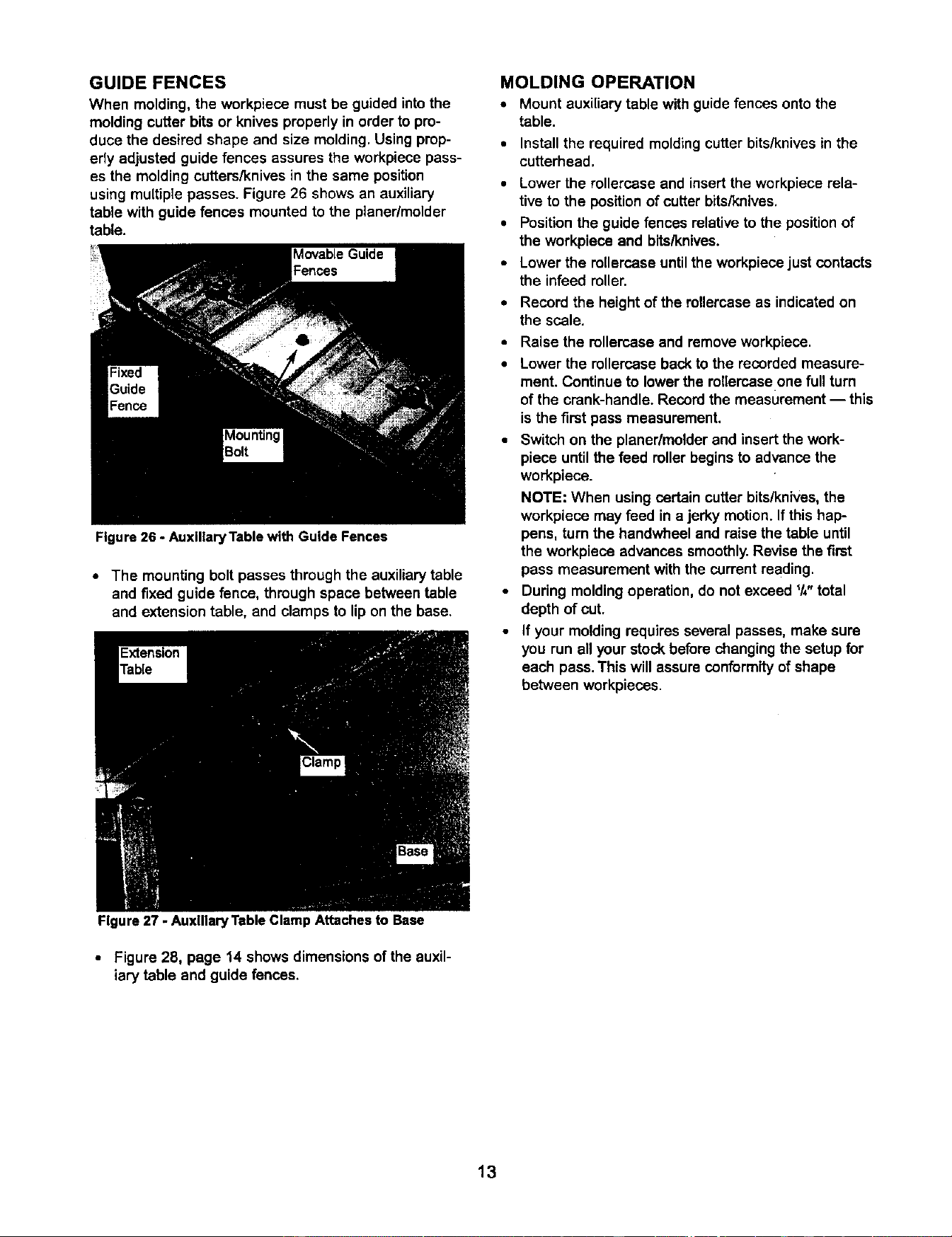
using multiple passes. Figure 26 shows an auxiliary
table with guide fences mounted to the planer/molder
table.
Figure 26 - AuxlliaryTable with Guide Fences
• The mounting boltpasses through the auxiliarytable
and fixed guide fence, through space between table
and extensiontable, and clamps to lipon the base.
Figure 27 - Auxiliary Table Clamp Attaches to Base
MOLDING OPERATION
• Mount auxiliarytable withguide fences ontothe
table.
• Install the required moldingcutter bits/knives in the
cutterhead.
• Lower the rollercaseand insert the workpiecerela-
tiveto the positionof cutter bits/knivas.
• Positionthe guide fencesrelativeto the positionof
the workpiece and bits/knives.
• Lower the rollercaseuntilthe workpiecejust contacts
the infeedroller.
• Record the height of the rollercaseas indicatedon
the scale.
• Raise the rellercase and removeworkpiece.
• Lower the rollercasebacktothe recordedmeasure-
ment. Continueto lowerthe rollercaseone fullturn
of the crank-handle.Recordthe measurement-- this
isthe first pass measurement.
• Switch on the planer/molderand insertthe work-
piece untilthe feed rollerbegins toadvance the
workpiece.
NOTE: When usingcertain cutterbits/knives,the
workpiece may feed in a jerky motion.Ifthis hap-
pens, turnthe bandwheel and raise the table until
the workpiece advances smoothly.Revise the first
pass measurement with the current reading.
• During moldingoperation,do not exceed I/," total
depth of cut.
• If your moldingrequiresseveral passes, make sure
you runall yourstockbeforechangingthe setup for
each pass.This will assure conformity of shape
between workpieces.
• Figure 28, page 14 shows dimensionsof the auxil-
iary table and guide fences.
13
Loading ...
Loading ...
Loading ...