User Manual LiftMaster 8587 3/4 HP AC Chain Drive Garage Door Opener
Installation
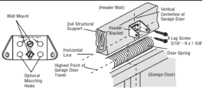
1. Determine the header bracket location
NOTE: If you are installing the garage door opener on a one-piece door. isitwww.liftmaster.com for installation instructions.
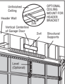
1.1 Close the door and mark the inside vertical centerline ofthe garage door.
1.2 Extend the line onto the header wall above the door. You can fasten the headerbracket within 4 feet (1.22 m) of the left orright of the door centeronly if a torsion spring orcenterbearing plate is in the way; oryou can attach it to the ceiling when clearance is minimal.(It may be mounted on the wallupside down if necessary. o gain approximately 1/2" (1 cm). If you need to install the header bracketon a 2x4 (on wall or ceiling). se lag screws (not provided) to securely fasten the 2x4 to structural supports.
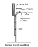
1.3 Open your door to the highestpointoftravel as shown.Draw an intersecting horizontal line on the header wall 2" (5 cm) above the high point.This heightwill provide travel clearance for the top edge ofthe door.
NOTE: Ifthe total number ofinches exceeds the heightavailable in your garage. se the maximum heightpossible. r refer to page 8 for ceiling installation.
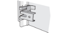
2. Install the Header Bracket
You can attach the header bracketeither to the wall above the garage door, or to the ceiling. Follow the instructions which will work bestfor your particular requirements. Do not installthe headerbracket overdrywall.If installing into masonry, use concrete anchors (not provided).
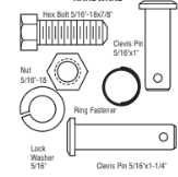
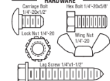
HARDWARE
OPTION A WALL INSTALLATION
2.1A Center the bracketon the vertical centerline with the bottom edge ofthe bracketon the horizontal line as shown (with the arrow pointing toward the ceiling).
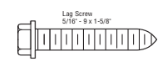
2.2A Mark the vertical setofbracketholes (do notuse the holes designated for ceiling mount).Drill 3/16" pilotholes and fasten the bracketsecurely to a structural supportwith lag screws.
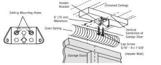
OPTION B CEILING INSTALLATION
2.1B Extend the vertical centerline onto the ceiling as shown.
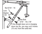
2.2B Center the bracketon the vertical mark, no more than 6" (15 cm) from the wall. Make sure the arrow is pointing toward the wall.The bracketcan be mounted flush againstthe ceiling when clearance is minimal.
2.3B Mark the side holes. Drill 3/16" pilotholes and fasten bracketsecurely to a structural supportwith lag screws.
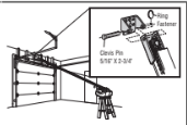
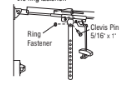
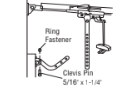
3. Attach the rail to the header bracket
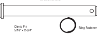
3.1 Align the rail with the header bracket. Insert the clevis pin through the holes in the header bracketand rail.Secure with the ring fastener.
NOTE: Use the packing material as a protective base for the garage door opener.
HARDWARE
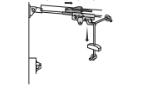
4 Position the garage door opener
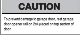
4.1 Remove the packing material and liftthe garage door opener onto a ladder.
NOTE: A 2x4 is ideal for setting the distance between the rail and the door.Ifthe ladder is nottall enough you will need help atthis point.
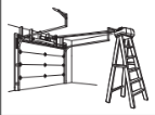
4.2 Fully open the door and place a 2x4 (laid flat) under the rail.
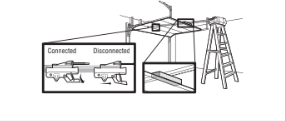
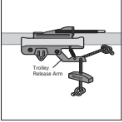
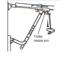
NOTE: Ifthe door hits the trolley when itis raised. ull the trolley release arm down to disconnectthe inner and outer trolley.Slide the outer trolley toward the garage door opener.
The trolley can remain disconnected until instructed.
5. Hang the garage door opener
WARNING
To avoid possible SERIOUS INJURY from a falling garage door opener. asten itSECURELY to structural supports ofthe garage.Concrete anchors MUST be used ifinstalling ANY brackets into masonry.
HARDWARE
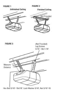
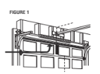
Hanging your garage door opener will vary depending on your garage.Two representative installations are shown.Yours may be different.
Hanging brackets should be angled (Figure 1) to provide rigid support.On finished ceilings (Figure 2). ttach a sturdy metal bracketto structural supports before installing the opener.This bracketand fastening hardware are notprovided.
Instructions below are for attaching the garage door opener directly to structural supports.
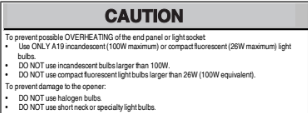
5.1 Measure the distance from each side ofthe motor unitto the structural support.
5.2 Cutboth pieces ofthe hanging bracketto required lengths.
5.3 Drill 3/16" pilotholes in the structural supports.
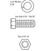
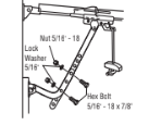
5.4 Attach one end ofeach bracketto a supportwith 5/16"-18x1-7/8" lag screws (notprovided).
5.5 Fasten the opener to the hanging brackets with 5/16"-18x7/8" hex bolts, ock washers and nuts.
5.6 Check to make sure the rail is centered over the door (or in line with the header bracketifthe bracketis notcentered above the door).
5.7 Remove the 2x4.Operate the door manually.Ifthe door hits the rail. aise the header bracket.
NOTE: DO NOT connectpower to opener atthis time.
6. Install the light bulbs
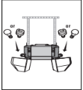
6.1 Pull on the top center ofthe lightlens and rotate the lightlens down.
6.2 Insertan A19 incandescent(100W maximum) or compactfluorescent(26W. 00W equivalent) light bulb into the lightsocket.
NOTE: Do notuse halogen. hortneck. r specialty light bulbs as these may overheatthe end panel or lightsocket. Do notuse LED bulbs as they may reduce the range or performance ofyour remote control(s).
6.3 Rotate the lens up to close.
7. Attach the emergency release rope and handle
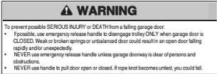
7.1 Insert one end ofthe emergency release rope through the handle.Make sure that“NOTICE” is rightside up.Tie a knotatleast1 inch (2.5 cm) from the end ofthe emergency release rope.
7.2 Inser tthe other end ofthe emergency release rope through the hole in the trolley release arm. Mount the emergency release within reach. utatleast6 feet(1.83 m) above the floor. voiding contactwith vehicles to preventaccidental release and secure with a knot.
NOTE: Ifitis necessary to cutthe emergency release rope. seal the cutend with a match or lighter to prevent unraveling.Ensure the emergency release rope and handle are above the top ofall vehicles to avoid entanglement.
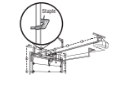
8. Install the door bracket
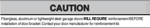
Figure 1 shows one piece ofangle iron as the horizontal brace. For the vertical brace. pieces ofangle iron are used to create a U-shaped support.The bestsolution is to check with your garage door manufacturer for an opener installation door reinforcement kit.
NOTE: Many door reinforcementkits provide for directattachment ofthe clevis pin and door arm.In this case you will notneed the door bracket;proceed to the nextstep.
HARDWARE

SECTIONAL DOORS
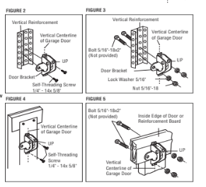
8.1 Center the door bracketon the previously marked vertical centerline used for the header bracket installation. Note correct UP placement, as stamped inside the bracket.
8.2 Position the top edge ofthe bracket2"-4" (5-10 cm) below the top edge ofthe door, OR directly below any structural supportacross the top ofthe door.
8.3 Mark, drill holes and install as follows, epending on your door’s construction:
Metalorlight weight doors using a verticalangle iron brace between the doorpanelsupport and the doorbracket:
- Drill 3/16" fastening holes. Secure the door bracketusing the two selfthreading screws. (Figure 2)
- Alternately, use two 5/16" bolts lock washers and nuts (notprovided),(Figure 3)
Metal insulated orlight weight factory reinforced doors:
- Drill 3/16" fastening holes.Secure the door bracketusing the self-threading screws (Figure 4)
Wood Doors:
- Use top and bottom or side to side door bracketholes. Drill 5/16” holes through the door and secure bracketwith 5/16"-18x2" carriage bolts. ock washers and nuts (notprovided) (Figure 5)
NOTE: The 1/4"-14x5/8" self-threading screws are notintended for use on wood doors.
A horizontal and vertical reinforcement is needed for lightweight garage doors (fi berglass. aluminum, steel, doors with glass panel, etc.) (not provided).
A horizontal reinforcement brace should be long enough to be secured to two or three vertical supports. A vertical reinforcement brace should cover the height of the top panel.
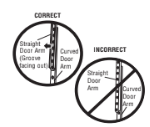
9. Connect the door arm to the trolley
IMPORTANT: The groove on the straight door arm MUST face away from the curved door arm.
HARDWARE
9.1 Close the door. Disconnectthe trolley by pulling the emergency release handle. Slide the outer trolley back (away from the door) about2" (5 cm).
9.2 Attach the straightdoor arm to the outer trolley using the clevis pin. Attach with the ring fastener.
9.3 Attach the curved door arm to the door bracket using the clevis pin. Attach with the ring fastener.
9.4 Align the straight door arm with the curved door arm. Select two aligned holes (as far apart as possible) and attach using the bolts, nuts and lock washers.
NOTE: If the holes do not line up, reverse the straight door arm. Select two aligned holes (as far apart as possible) and attach using the bolts, nuts and lock washers.
9.5 Pull the emergency release handle toward the garage door opener until the trolley release arm is horizontal. The trolley will re-engage automatically when the garage door opener is activated.
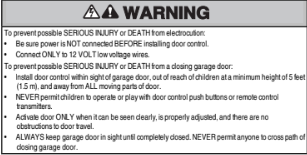
Install the Door Control
1. Install the door control
INTRODUCTION
Compatible with MyQ and Security+2.0 accessories. ee page 35.Your garage door opener is compatible with up to 2 SmartControl Panels or 4 ofany other Security+2.0 door controls. NOTE: Older LiftMaster door controls and third party products are notcompatible.
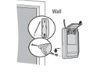
Install the door control within sightofthe door at a minimum heightof5 feet(1.5 m) where small children cannotreach. nd away from the moving parts ofthe door.
NOTE: Your productmay look differentthan moving parts ofthe door the illustrations.
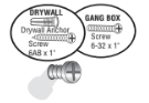
HARDWARE
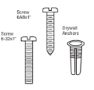
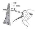
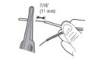
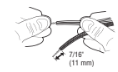
1.1 Strip 7/16 inch (11 mm) ofinsulation from one end ofthe wire and separate the wires.
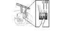
1.2 Connectone wire to each ofthe two screws on the back ofthe door control.The wires can be connected to either screw. PRE-WIRED INSTALLATIONS: Choose any two wires to connect. ote which wires are used so the correctwires are connected atthe garage door opener in a later step.
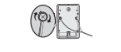
1.3 Mark the location ofthe bottom mounting hole and drill a 5/32 inch (4 mm) hole.
1.4 Install the bottom screw. llowing 1/8 inch (3 mm) to protrude from the wall.
1.5 Position the bottom hole ofthe door control over the screw and slide down into place.
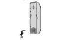
1.6 Liftthe push bar up and mark the top hole.
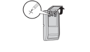
1.7 Remove the door control from the wall and drill a 5/32 inch (4 mm) hole for the top screw.
1.8 Position the bottom hole ofthe door control over the screw and slide down into place. Attach the top screw.

2. Wire the door control to the garage door opener
HARDWARE
PRE-WIRED INSTALLATIONS: When wiring the door control to the garage door opener make sure you use the same wires thatare connected to the door control.
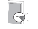
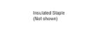
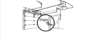
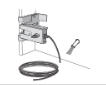
2.1 Run the white and red/white wire from the door control to the garage door opener.Attach the wire to the wall and ceiling with the staples (notapplicable for gang box or pre-wired installations). Do notpierce the wire with the staple as this may cause a shortor an open circuit.
2.2 Strip 7/16 inch (11 mm) ofinsulation from the end ofthe wire near the garage door opener.
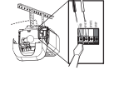
2.3 Connectthe wire to the red and white terminals on the garage door opener. To insertor release wires from the terminal, push in the tab with screwdriver tip.
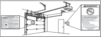
3. Attach the warning labels
3.1 Attach the entrapmentwarning label on the wall near the door control with tacks or staples.
3.2 Attach the manual release/safety reverse testlabel in a visible location on the inside of the garage door.
Install the Protector System
1. Install the Safety Reversing Sensors
The safety reversing sensors can be attached to the door track, the wall, or the floor. If the door track will notsupportthe sensor bracketa wall installation is recommended. Choose one ofthe following installations.
HARDWARE
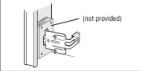
OPTION A DOOR TRACK INSTALLATION
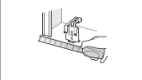
1.1A Slide the curved arms ofthe sensor bracketaround the edge ofthe door track. Snap into place so thatthe sensor bracketis flush againstthe track.
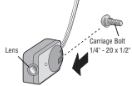
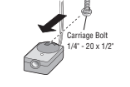
1.2A Slide the carriage boltinto the sloton each sensor.
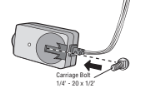
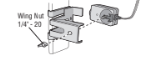
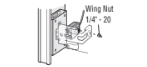
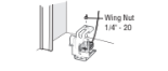
1.3A Insert the bolt through the hole in the sensor bracketand attach with the wing nut. The lenses on both sensors should pointtoward each other. Make sure the lens is notobstructed by the sensor bracket.
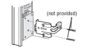
OPTION B WALL INSTALLATION
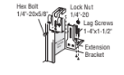
If additional clearance is needed an extension bracket(notprovided) or wood blocks can be used. Make sure each brackethas the same amountofclearance so they will align correctly.
1.1B Position the sensor bracketagainstthe wall with the curved arms facing the door.Make sure there is enough clearance for the beam to be unobstructed. Mark holes.
1.2B Drill 3/16 inch pilotholes for each sensor bracketand attach the sensor brackets to the wall using lag screws (not provided).
1.3B Slide the carriage boltinto the sloton each sensor.
1.4B Insertthe boltthrough the hole in the sensor bracketand attach with the wing nut.The lenses on both sensors should pointtoward each other.Make sure the lens is notobstructed by the sensor bracket.
OPTION C FLOOR INSTALLATION
Use an extension bracketor wood block to raise the sensor bracketifneeded.
1.1C Carefully measure the position ofboth sensor brackets so they will be the same distance from the wall and unobstructed.
1.2C Attach the sensor brackets to the floor using concrete anchors.
1.3C Slide the carriage boltinto the sloton each sensor.
1.4C Insertthe boltthrough the hole in the sensor bracketand attach with the wing nut.The lens on both sensors should pointtoward each other.Make sure the lens is notobstructed by the sensor bracket.
2. Wire the Safety Reversing Sensors
PRE-WIRED INSTALLATIONS: If your garage already has wires installed for the safety reversing sensors. See page 20.
HARDWARE
OPTION A INSTALLATION WITHOUT PRE-WIRING
2.1A Run the wire from both sensors to the garage door opener.Attach the wire to the wall and ceiling with the staples.
2.2A Strip 7/16 inch (11 mm) ofinsulation from each setofwires.Separate the wires.Twistthe white wires together.
2.3A Insert the white wires into the white terminal on the garage door opener. Insert the white/black wires into the grey terminal on the garage door opener. To insertor remove the wires from the terminal. Push in the tab with a screwdriver tip.
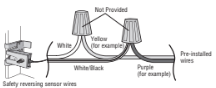
OPTION B PRE-WIRED INSTALLATION
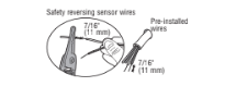
2.1B Cutthe end ofthe safety reversing sensor wire. Making sure there is enough wire to reach the pre-installed wires from the wall.
2.2B Separate the safety reversing sensor wires and strip 7/16 inch (11 mm) of insulation from each end.Choose two ofthe pre-installed wires and strip 7/16 inch (11 mm) ofinsulation from each end.Make sure thatyou choose the same color pre-installed wires for each sensor.
2.3B Connectthe pre-installed wires to the sensor wires with wire nuts making sure the colors correspond for each sensor.For example. the white wire would connectto the yellow wire and the white/black wire would connectto the purple wire.
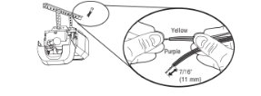
2.4B Atthe garage door opener, trip 7/16 inch (11 mm) ofinsulation from each end ofthe wires previously chosen for the safety reversing sensors.Twistthe like-colored wires together.
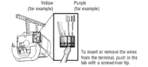
2.5B Insert the wires connected to the white safety sensor wires to the white terminal on the garage door opener. Insert the wires thatare connected to the white/black safety sensor wires to the grey terminal on the garage door opener.
Power
1. Connect Power
To avoid installation difficulties, do not activate the garage dooropenerat this time.
To reduce the risk ofelectric shock. our garage door opener has a grounding type plug with a third grounding pin.This plug will only fitinto a grounding type outlet.Ifthe plug doesn’tfitinto your outlet. contacta qualified electrician to install the proper outlet.
THERE ARE TWO OPTIONS FOR CONNECTING POWER:
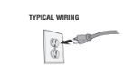
OPTION A TYPICAL WIRING
1.1A Plug in the garage door opener into a grounded outlet.
1.2A DO NOT run garage door opener atthis time.
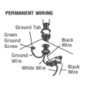
OPTION B PERMANENT WIRING
If permanent wiring is required by yourlocalcode. eferto the following procedure.
To make a permanent connection through the 7/8 inch hole in the top of the motorunit (according to localcode):
1.1B Remove the motor unitcover screws and setthe cover aside.
1.2B Remove the attached 3-prong cord.
1.3B Connectthe black (line) wire to the screw on the brass terminal;the white (neutral) wire to the screw on the silver terminal;and the ground wire to the green ground screw.The openermust be grounded.
1.4B Reinstall the cover.
2 Ensure the Safety Reversing Sensors are aligned
The doorwillnot close if the sensors have not been installed and aligned correctly.
When the lightbeam is obstructed or misaligned while the door is closing. he door will reverse and the garage door opener lights will flash ten times.Ifthe door is already open. twill notclose.The sensors can be aligned by loosening the wing nuts. ligning the sensors. nd tightening the wing nuts.
2.1 Check to make sure the LEDs in both sensors are glowing steadily.The LEDs in both sensors will glow steadily ifthey are aligned and wired correctly.
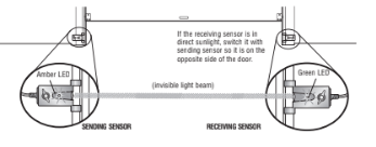
IF THE AMBER LED ON THE SENDING SENSOR IS NOT GLOWING:
Make sure there is power to the garage door opener.

Make sure the sensor wire is not shorted/broken.

Make sure the sensor has been wired correctly: white wires to white terminal and white/black wires to grey terminal.
IF THE GREEN LED ON THE RECEIVING SENSOR IS NOT GLOWING:
Make sure the sensors are aligned.

Make sure the sensor wire is not shorted/broken.
3 Ensure the Door Control is wired correctly
If the door control has been installed and wired correctly a message will display on the screen.
Adjustments
INTRODUCTION
Your garage door opener is designed with electronic controls to make setup and adjustments easy.The adjustments allow you to program where the door will stop in the open (UP) and close (DOWN) position.The electronic controls sense the amountofforce required to open and close the door.The force is adjusted automatically when you program the travel.
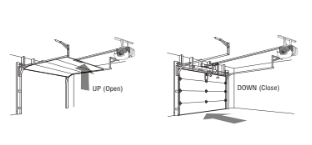
NOTE: Ifanything interferes with the door’s upward travel itwill stop.If anything interferes with the door’s downward travel. twill reverse.
To watch a shortinstructional video on programming your new garage door opener use your smartphone to read the QR Code below:
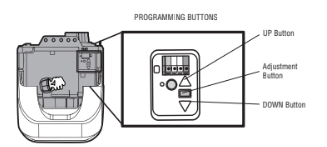
PROGRAMMING BUTTONS
The programming buttons are located on the leftside panel ofthe garage door opener and are used to program the travel.
Features
Your garage door opener is equipped with features to provide you with greater control over your garage door operation.
Alert2Close
The Alert2Close feature provides a visual and an audible alertthatan unattended door is closing.
Timer-to-Close (TTC)
The TTC feature automatically closes the door after a specified time period thatcan be adjusted using a TTC enabled door control (Models 881LM or 880LM).Prior to and during the door closing the garage door opener lights will flash and the garage door opener will beep.
MyQ
MyQ technology uses a 900MHz signal to provide two-way communication between the garage door opener and MyQ enabled accessories.Your garage door opener is compatible with up to 16 MyQ
SECURITY+ 2.0TM REMOTE CONTROLS AND DOOR CONTROLS
Your garage door opener has already been programmed at the factory to operate with your remote control, which changes with each use, randomly accessing over 100 billion new codes. Compatible with MyQ® and Security+ 2.0TM accessories, see page 35.
NOTE: Older LiftMaster remote controls, door controls, and third party products are not compatible.
THE PROTECTOR SYSTEM (SAFETY REVERSING SENSORS)
When properly connected and aligned. he safety reversing sensors will detectan obstruction in the path ofthe infrared beam.Ifan obstruction breaks the infrared beam while the door is closing. he door will stop and reverse to full open position. nd the opener lights will flash 10 times.Ifthe door is fully open. nd the safety reversing sensors are notinstalled. r are misaligned. he door will notclose from a remote control.However. ou can close the door ifyou hold the button on the door control or keyless entry until the door is fully closed.The safety reversing sensors do notaffectthe opening cycle.
ENERGY CONSERVATION
For energy efficiency the garage door opener will enter sleep mode when the door is fully closed.The sleep mode shuts the garage door opener down until activated.The sleep mode is sequenced with the garage door opener lightbulb;as the lightbulb turns offthe sensor LEDs will turn offand whenever the garage door opener lights turn on the sensor LEDs will light.The garage door opener will notgo into the sleep mode until the garage door opener has completed 5 cycles upon power up.
LIGHTS
The garage door opener lightbulbs will turn on when the opener is initially plugged in;power is restored after interruption. r when the garage door opener is activated.The lights will turn off automatically after 4-1/2 minutes.An incandescentA19 lightbulb (100 wattmaximum) or for maximum energy efficiency a 26W (100W equivalent) compactfluorescentlight(CFL) bulb may be used.
Light Feature
The garage door opener is equipped with an added feature;the lights will turn on when someone enters through the open garage door and the safety reversing sensor infrared beam is broken.For added control over the lightbulbs on your garage door opener. ee page 29.
USING YOUR GARAGE DOOR OPENER
The garage door opener can be activated through a wall-mounted door control. emote control. wireless keyless entry or MyQ accessory.When the door is closed and the garage door opener is activated the door will open.Ifthe door senses an obstruction or is interrupted while opening the door will stop.When the door is in any position other than closed and the garage door opener is activated the door will close.Ifthe garage door opener senses an obstruction while closing. he door will reverse.
If the obstruction interrupts the sensor beam the garage door opener lights will blink 10 times.However. you can close the door ifyou hold the button on the door control or keyless entry until the door is fully closed.The safety reversing sensors do notaffectthe opening cycle.The safety reversing sensor must be connected and aligned correctly before the garage door opener will move in the down direction.
Door Control
USING THE DOOR CONTROL
SYNCHRONIZE THE DOOR CONTROL
To synchronize the door control to the garage door opener. ress the push bar until the garage door opener activates (itmay take up to 3 presses).Testthe door control by pressing the push bar. ach press ofthe push bar will activate the garage door opener.
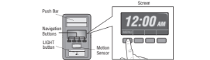
PUSH BAR
Press the push bar to open or close the door.
NAVIGATION BUTTONS
Use the navigation buttons to make selections and program features.
LIGHT BUTTON
Press the LIGHT button to turn the garage door opener lights on or off.When the lights are turned on they will stay on until the LIGHT button is pressed again. r until the garage door opener is activated. Once the garage door opener is activated the lights will turn offafter the specified period oftime (the factory setting is 4-1/2 minutes).The LIGHT button will notcontrol the lights when the door is in motion. The duration ofthe lighttiming can be adjusted by accessing the menu using the navigation buttons.
SCREEN
The screen will display the time and temperature until the menu button is pressed. nd then itwill display the menu options.Ifthere is a problem with the garage door opener the screen will display the Diagnostic Code.Refer to the Troubleshooting section.
The following features are accessible through the screen using the navigation buttons: LEARN A DEVICE
Any compatible remote controls. ireless keyless entry. r MyQ accessories can be programmed to the garage door opener by accessing the menu and using the navigation buttons.
LOCK
The LOCK feature is designed to preventactivation ofthe garage door opener from remote controls while still allowing activation from the door control and keyless entry.This feature is useful for added peace ofmind when the home is empty (i.e.vacation).
TIMER-TO-CLOSE (TTC)
DO NOT enable TTC ifoperating a one-piece door.TTC is to be used ONLY with sectional doors. Factory defaultis setto off. TTC can be setto automatically close your garage door from the fully open position after a specified period oftime (1.. 0 minute intervals).The garage door opener will Beep and the lights will Flash before closing the door.The screen on the door control can display the status of the TTC.TTC WILL NOT work ifthe garage door opener is operating by battery power or ifthe safety reversing sensors are misaligned.This feature is NOT intended to be the primary method ofclosing the door.A keyless entry should be installed in the event of an accidentallock out when using this feature.
NOTE: Before enabling the TTC for the firsttime. r ifyou experience a power outage. ycle the garage door opener open and closed to allow the TTC to set.
AUTOMATIC LIGHT
Motion Sensor
Factory defaultis setto on.This feature automatically turns on the garage door opener lights when motion is sensed.The lights will come on for the setperiod oftime. hen shutoff.Ifusing the garage door opener lightas a work lightdisable the motion sensor. therwise the lightwill turn offautomatically ifyou are beyond the range ofthe sensor.
Light Feature
The lights will turn on when someone enters through the open garage door and the safety reversing sensor infrared beam is broken.
MAINTENANCE ALERT (MAS)
his feature assists the homeowner in ensuring the garage door opener system stays in good working condition.A maintenance alertmessage will display on the screen indicating the garage door opener may be in need ofmaintenance. The factory setting for the MAS feature is offand can be activated at time ofinstallation.Contactyour installing dealer for service.
Maintenance
EVERY MONTH
- Manually operate door.Ifitis unbalanced or binding. all a trained door systems technician.
- Check to be sure door opens and closes fully. Adjustifnecessary. See page 24.
- Test the safety reversal system.Adjustifnecessary. See page 25.
EVERY YEAR
- Oil door rollers. earings and hinges.The garage door opener does notrequire additional lubrication.Do notgrease the door tracks.
EVERY TWO TO THREE YEARS
- Use a rag to wipe away the existing grease from the garage door opener rail.Reapply a small layer ofwhite lithium grease to the top and underside ofthe rail surface where the trolley slides.
NOTICE: To comply with FCC and/orIndustry Canada (IC) rules. djustment or modificationsof thistransceiver are prohibited. THERE ARE NO USER SERVICEABLE PARTS. Any changes or modifications not expresslyapproved by the party responsible for compliance could void the user'sauthorityto operate the equipment.
This device complieswith Part15 ofthe FCC rulesand IC RSS-210. Operation issubjectto the following two conditions:(1)thisdevice may not cause harmful interference. and (2) this device must accept any interference received. including interference that may cause undesired operation.
DISCONNECT THE TROLLEY
- The door should be fully closed if possible.
- Pull down on the emergency release handle.

RECONNECT THE TROLLEY
The lockout feature prevents the trolley from reconnecting automatically.
- Pull the emergency release handle down and back (toward the opener). The door can then be raised and lowered manually as often as necessary.
- To disengage the lockout feature, pull the handle straight down. The trolley will reconnect on the next UP or DOWN operation, either manually or by using the door control or remote control.

THE REMOTE CONTROL BATTERY
To preventpossible SERIOUS INJURY or DEATH:
- NEVER allow small children near batteries.
- If battery is swallowed. mmediately notify doctor.
To reduce risk offire. xplosion or chemical burn:
- Replace ONLY with 3V2016 coin batteries.
- DO NOT recharge. isassemble. eatabove 212°F (100°C) or incinerate.
To replace the batteries. emove the two screws and open the remote control housing.Push the battery outofthe holder for removal.Insert replacementbatteries positive side up (+).
Troubleshooting
The garage door opener can beep for several reasons:
- Garage door opener has been activated through a device or feature such as Timer-to- Close, garage door monitor or LiftMaster Internet Gateway, see page 27.
My remote control will not activate the garage door:
- Verify the lock feature is not activated on the door control.
- Reprogram the remote control.
- If the remote control will still not activate the door check the diagnostic codes to ensure the garage door opener is working properly.
My door will not close and the light bulbs blink on my motor unit:
The safety reversing sensor must be connected and aligned correctly before the garage door opener will move in the down direction.
- Verify the safety sensors are properly installed, aligned and free of any obstructions.
My garage door opener light(s) will not turn off when the dooris open:
The garage door opener is equipped with a feature that turns the light on when the safety reversing sensors have been obstructed or when the motion sensor on the door control detects movement in the garage. These features can be disabled using the door control, see page 31 .
My neighbor’s remote control opens my garage door:
Erase the memory from your garage door opener and reprogram the remote control(s).
The LEDs on the door control blink:
If you have a Smart Control Panel installed and the TTC is set to a custom time, press the ON button on the Premium Motion-Detecting Control Panel to set the time properly.
My vehicle's Homelink® is not programming to my garage door opener:
Depending on the make, model, and year of your vehicle an external adapter may be required. Visit www.homelink.com for additional information.
Warranty
LIFTMASTER® FIVE YEAR LIMITED WARRANTY LIFETIME MOTOR LIMITED WARRANTY
The Chamberlain Group, Inc. (“Seller”) warrants to the fi rst retail purchaser of this product, for the residence in which this product is originally installed, that it is free from defects in materials and/or workmanship for a period of fi ve years from the date of purchase, except that the motor is warranted to be free from defects in materials and/or workmanship for the lifetime of the product while you own your residence,. The proper operation of this product is dependent on your compliance with the instructions regarding installation, operation, and maintenance and testing. Failure to comply strictly with those instructions will void this limited warranty in its entirety.
If, during the limited warranty period, this product appears to contain a defect covered by this limited warranty, call 1-800-528-9131, toll free, before dismantling this product. You will be advised of disassembly and shipping instructions when you call. Then send the product or component, pre-paid and insured, as directed to our service center for warranty repair. Please include a brief description of the problem and a dated proof-of-purchase receipt with any product returned for warranty repair. Products returned to Seller for warranty repair, which upon receipt by Seller are confi rmed to be defective and covered by this limited warranty, will be repaired or replaced (at Seller’s sole option) at no cost to you and returned pre-paid. Defective parts will be repaired or replaced with new or factory-rebuilt parts at Seller’s sole option. [You are responsible for any costs incurred in removing and/or reinstalling the product or any component .]
ALL IMPLIED WARRANTIES FOR THE PRODUCT, INCLUDING BUT NOT LIMITED TO ANY IMPLIED WARRANTIES OF MERCHANTABILITY AND FITNESS FOR A PARTICULAR PURPOSE, ARE LIMITED IN DURATION TO THE APPLICABLE LIMITED WARRANTY PERIOD SET FORTH ABOVE FOR THE RELATED COMPONENT(S), AND NO IMPLIED WARRANTIES WILL EXIST OR APPLY AFTER SUCH PERIOD. Some States do not allow limitations on how long an implied warranty lasts, so the above limitation may not apply to you. THIS LIMITED WARRANTY DOES NOT COVER NON-DEFECT DAMAGE, DAMAGE CAUSED BY IMPROPER INSTALLATION, OPERATION OR CARE (INCLUDING, BUT NOT LIMITED TO ABUSE, MISUSE, FAILURE TO PROVIDE REASONABLE AND NECESSARY MAINTENANCE, UNAUTHORIZED REPAIRS OR ANY ALTERATIONS TO THIS PRODUCT), LABOR CHARGES FOR REINSTALLING A REPAIRED OR REPLACED UNIT, REPLACEMENT OF CONSUMABLE ITEMS (E.G., BATTERIES IN REMOTE CONTROL TRANSMITTERS AND LIGHT BULBS), OR UNITS INSTALLED FOR NON-RESIDENTIAL USE. THIS LIMITED WARRANTY DOES NOT COVER ANY PROBLEMS WITH, OR RELATING TO, THE GARAGE DOOR OR GARAGE DOOR HARDWARE, INCLUDING BUT NOT LIMITED TO THE DOOR SPRINGS, DOOR ROLLERS, DOOR ALIGNMENT OR HINGES. THIS LIMITED WARRANTY ALSO DOES NOT COVER ANY PROBLEMS CAUSED BY INTERFERENCE. UNDER NO CIRCUMSTANCES SHALL SELLER BE LIABLE FOR CONSEQUENTIAL, INCIDENTAL OR SPECIAL DAMAGES ARISING IN CONNECTION WITH USE, OR INABILITY TO USE, THIS PRODUCT. IN NO EVENT SHALL SELLER’S LIABILITY FOR BREACH OF WARRANTY, BREACH OF CONTRACT, NEGLIGENCE OR STRICT LIABILITY EXCEED THE COST OF THE PRODUCT COVERED HEREBY. NO PERSON IS AUTHORIZED TO ASSUME FOR US ANY OTHER LIABILITY IN CONNECTION WITH THE SALE OF THIS PRODUCT.
Some states do not allow the exclusion or limitation of consequential, incidental or special damages, so the above limitation or exclusion may not apply to you. This limited warranty gives you specifi c legal rights, and you may also have other rights, which vary from state to state.