Total Install Length
Depends on door height.
See #7 details below...
Low Voltage
Stranded
2-Conductor
Bell Wire From
Photo Eye to
Junction Box
(22 gauge
bell wire
Recommended)
Low Voltage
Stranded
2-Conductor
Bell Wire From
Photo Eye to
Junction Box
(22 gauge
bell wire
Recommended)
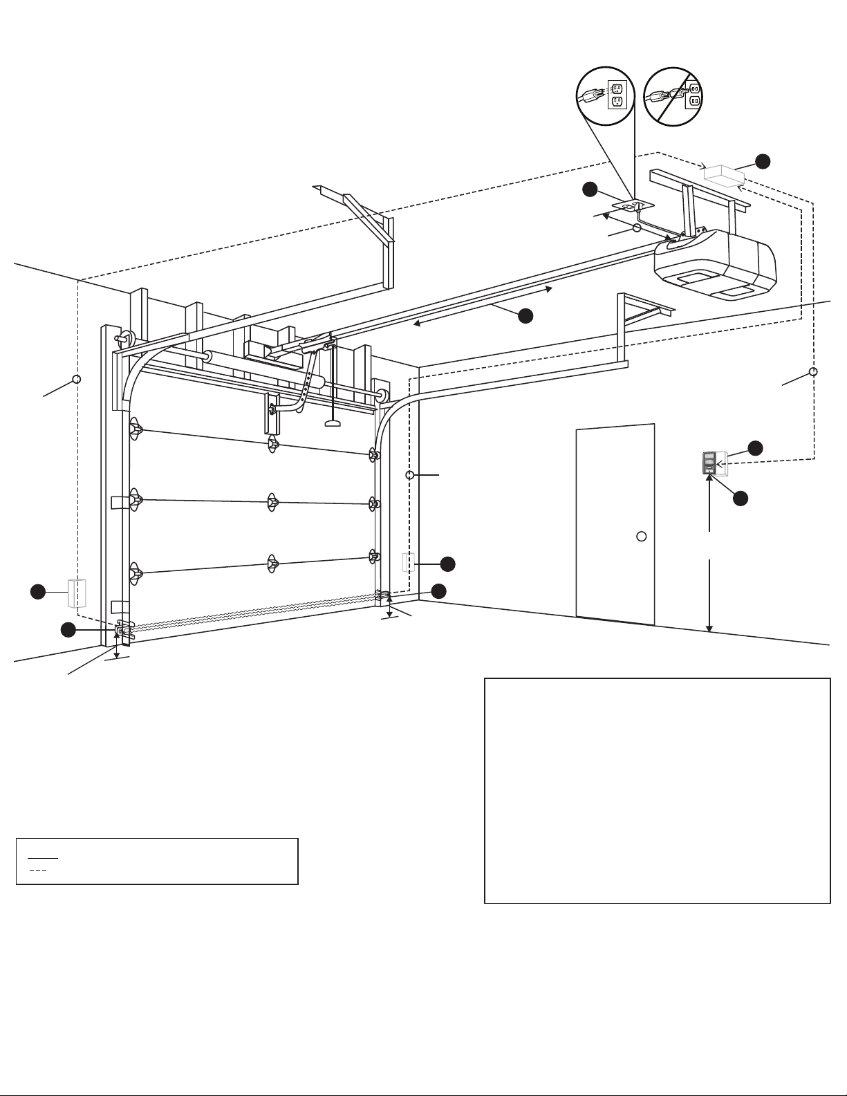
Wiring Diagram For Rail Trolley Garage Door Operators
Required: Install
Wall-mounted
Garage Door
Control Out of
Reach of Small
Children at a
Minimum Height of
5’ ft. Above Floors
or Any Other
Adjacent Walking
Surface.
Low Voltage
Stranded
2-Conductor
Bell Wire From
Junction Box To
Wall-Mounted
Door Control
(22 gauge
bell wire
Recommended)
60” in.
(Minimum)
*Min 12” in.
Max 4’ ft.
1
4
1
2
3
7
5
300 Windsor Drive
Oak Brook, IL 60523
LiftMaster.com
© 2019, The Chamberlain Group, Inc. - All Rights Reserved
114-5400
Legend
Low voltage stranded 2-conductor bell wire, minimum 22 AWG
Notes:
Junction boxes for low voltage wiring for the garage door accessories ideally will be
in a plastic gang box with a coaxial cable cover plate. Allow 2’ ft. of extra wiring at
the photo eye junction boxes and 3‘ to 4’ ft. of extra low voltage wiring near the
operator low voltage wiring junction box.
Junction boxes for wall station ideally will be in a plastic gang box. LiftMaster
Wall-Mounted Garage Door Control will screw into a gang box and act as a cover.
Multiple door gang boxes must be 2” in. apart. Junction box in ceiling by operator
should be 1’ ft. off-set and ideally should be in a plastic junction box with a coaxial
cable cover.
Wires can come directly out of wall, but for best finish install junction boxes as
noted above.
Dotted line wire depicted above can be stapled to wall or ran behind sheetrock and
does not require conduit.
*Cord length varies from 4’-6’ ft. depending on model of garage door opener.
Minimum of 12” in. is required between operator and electrical outlet.
1. Safety Sensors (Installed 6” In. Max Above Floors)
2. Gang box for all wires (Located Behind Opener)
3. *Grounded Outlet (Min. 12’ in. Away From Opener, Max 4’ ft.)
4. Door Control (Min. 60" in. Above Floor)
5. Door Control Gang Box - (Door Control Can be Mounted to the Junction Box).
6. Safety Sensor Junction Box, Behind Sheetrock (With Junction Box Cover on Wall)
7. Overall Opener Installation Length From the Front of the
Door to the Bracket to Mount the Garage Door Opener:
• 7 Foot Door Height = 124” in.
• 8 Foot Door Height = 136” in.
• 10 Foot Door Height = 166” in.
Max. 6” in.
Max 6” in.
6
6
Compliance with the NEC
It should be noted that placement of wiring should comply with the applicable provisions of the National Electrical Code (NEC), and/or state and/or local requirements, that govern the project being undertaken.
Important NEC Information
Do not run any low voltage control wires close to the 120-volt power line. Do not run any wires through the same holes as the 120-volt power line in studs or cross ties. Either of these conditions will not comply
with the NEC and may interfere with safe operation of the garage door operator.
120V AC,
60Hz