
© 2019, LiftMaster
All Rights Reserved114-5322-000
LMI5 Interface Accessory
WARNING: This product can expose you to chemicals
including lead, which are known to the State of
California to cause cancer or birth defects or other
reproductive harm. For more information go to
www.P65Warnings.ca.gov.
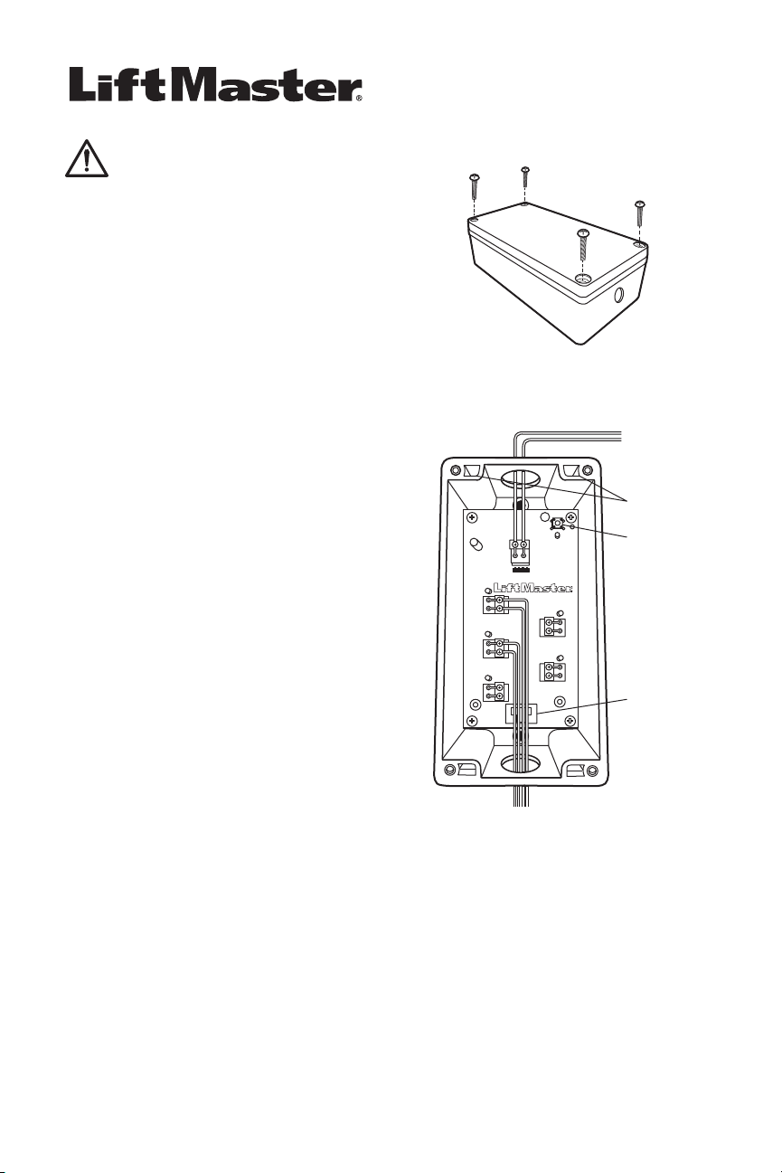
Figure 1
Figure 2
To Terminal 2 (Red)
To Terminal 3 (White)
Cut-out for
Cable Restraint
(cable tie to
secure wires
not included)
To Accessories
Mounting
Holes
SW1
Learn Button
LMi5 Interface Accessory
The LMi5 accessory provides the ability to monitor up to 5 sensors
around the dock door with the myQ
®
Business Facility. These
sensors provide the status of equipment to the myQ
®
Business
Facility.
Typical sensors include:
PRE-SENSOR: This is a trailer presence sensor to provide
status of whether a trailer is present at the
dock or not.
WS-SENSOR: This is a mechanical roller limit switch to
determine the status of a trailer restraint
system or position of a dock leveler
(deployed or stored)
WS-SENSOR-E: This is a photoelectrical sensor to determine
the status of a trailer restraint system or
position of a dock leveler (deployed or
stored)
Once the sensors are connected to the LMi5, go to www.
myQBusiness.com to set up your interface box confi guration and
name the connected sensors: (Normally Open/NO or Normally
Closed/NC). The default status is Normally Open.
Installation
1. Select a convenient location within 35' (10.6 m) of the
operator to mount the LMi5 accessory.
2. Remove the 4 screws on the cover of the LMi5 and remove
the cover (Figure 1)
3. Add 1/2" conduit connector or cable gland (not provided)
to top and bottom holes of LMi5 per requirements of
installation.
4. Make wire connections (Figure 2) from CMD (Command)
to Terminals 2 (red) and 3 (white) on the DDO8900W.
Recommended: solid wire 14-24AWG. Route wiring through
the top of LMi5.
5. Press the SW1 button to learn the LMi5 to the operator. The
LED should remain lit once learned.
6. Make wire connections (Figure 2) from ACCY (Accessory)
inputs to the sensors. Recommended: solid wire 14-24AWG.
NOTE: Provide all required power externally – Accessory
sensors cannot be powered from the LMi5 accessory. Route
all wiring for the sensors to the center of the board and down
through the bottom of the LMi5.
7. Toggle the accessory device (switch the state of the contact).
You should see the LED on the related LMi5 input change
state in response.
8. For wire retention of the various accessories, use the cutout
near the bottom of the board (see Figure 2) in conjunction
with a cable tie (not provided) to retain the various wires
from the sensors.
9. Secure the cover with the 4 screws provided.
