Extended Performance Release Device
OWNER’S MANUAL
Models: LM21XPBB, LM21XPBBVB
APPROVED
FM
LiftMaster
300 Windsor Drive
Oak Brook, IL 60523
LiftMaster.com
2
INTRODUCTION ...........................................2
General Description .........................................2
Agency Requirements .......................................2
Specifications .............................................3
Preparation ...............................................3
INSTALLATION ............................................4
Important Installation Warnings ...............................4
Mount the Release Device ....................................4
WIRING ..................................................5
Wiring Instructions .........................................5
Wire Routing ..............................................6
Wiring Diagram ............................................7
Connections of Initiating Devices and Accessories ................8
Optional Connections .......................................9
TESTING ................................................11
Test Procedures ..........................................11
TROUBLESHOOTING ......................................12
Operational Checklist ......................................12
Circuit Board Diagnostic LEDs ...............................13
Ground Fault Error .........................................13
MAINTENANCE ...........................................14
Maintenance Requirements .................................14
Enclosure Mounted LEDs Status Indicators .....................14
ACCESSORIES AND REPLACEMENT PARTS .................... 15
APPENDIX ...............................................16
Table of Contents
Introduction
When you see these Safety Symbols and Signal Words on the
following pages, they will alert you to the possibility of SERIOUS
INJURY or DEATH if you do not comply with the warnings that
accompany them. The hazard may come from something mechanical
or from electric shock. Read the warnings carefully.
When you see this Signal Word on the following pages, it will alert
you to the possibility of damage to your door and/or the door
operator if you do not comply with the cautionary statements that
accompany it. Read them carefully.
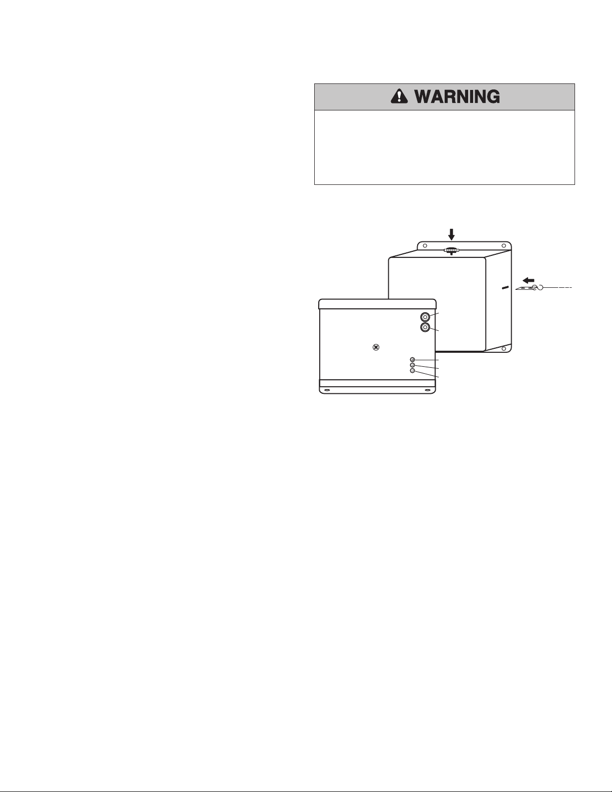
To prevent possible SERIOUS INJURY or DEATH:
• DO NOT use this device without fusible links installed.
• Test every 90 days to assure proper operation of release device.
Mechanical
Electrical
ENGLISH WARNINGS AT 50%
SPANISH WARNINGS AT 50%
FRENCH WARNINGS AT 50%
ENGLISH WARNINGS AT 50%
SPANISH WARNINGS AT 50%
FRENCH WARNINGS AT 50%
ENGLISH WARNINGS AT 50%
SPANISH WARNINGS AT 50%
FRENCH WARNINGS AT 50%
ENGLISH WARNINGS AT 50%
SPANISH WARNINGS AT 50%
FRENCH WARNINGS AT 50%
IMPORTANT NOTES:
• BEFORE attempting to install, operate or maintain the release device,
you must read and fully understand this manual and follow all safety
instructions.
• DO NOT attempt repair or service of your release device unless you
are an Authorized Service Technician.
GENERAL DESCRIPTION
The LiftMaster
®
LM21XPBB and LM21XPBBVB Release Device is
UL/ULC listed normally energized fail-safe device designed for use on
rolling doors, single-slide and center-parting level and inclined track
doors. All models are normally energized fail-safe releasing devices
incorporating state-of-the-art electronic control circuitry. The release
devices respond to emergency conditions generated from an automatic
initiating device and are used in conjunction with a fusible link system.
The release device can be powered from 120Vac, 24 Vac, or 24Vdc. The
24Vdc cannot be sourced from a fire alarm control panel or UL1481
regulated power supply. The devices can be activated via a smoke
detector or an alarm relay from the panel’s Form C dry contact relay.
The release device features include a 10, 20, 30 or 60 second delay on
alarm, closed door detection capabilities, Form C relay outputs for the
transmission of alarm and trouble signals transmitted to the fire alarm
control panel, an audible trouble sounder, and diagnostic feedback
LEDs. The release device is provided with a battery management
system that can provide 24Vdc power for up to four smoke detectors
and two horn strobes, as well as provide battery backup for the release
device and accessories. As with all releasing device systems, maximum
fire protection is provided when installed in accordance with factory
specifications and used with a fusible link systems.
AGENCY REQUIREMENTS
Installation and testing to factory specifications shall be performed by
factory authorized personnel for proper operation in accordance with
the latest National Fire Protection Association (NFPA), Underwriters
Laboratories (UL), National Electrical Code (NEC), local, state, county,
district and/or other applicable building and fire standards, guidelines,
regulations and codes including, but not limited to, all appendices
and amendments and the requirements of the local authority having
jurisdiction (AHJ).
WARNING: This product can expose you to chemicals including
lead, which are known to the State of California to cause
cancer or birth defects or other reproductive harm. For more
information go to www.P65Warnings.ca.gov
3
SPECIFICATIONS
PREPARATION
It is imperative that the wall or mounting surface provide adequate
support for the release device.
Refer to the door manufacturer’s recommendations for use of this
product with specific door being utilized. Use only hardware approved
or recognized by the appropriate testing and listing agencies in
conjunction with the installation of this product.
Additional items may be required to complete the installation:
• Concrete anchors or fasteners
• Sash chain or 1/16" cable
• Eyebolts-hook
• Fusible links
• Turnbuckles
• Smoke detectors (up to 4 may be installed with this device)
Refer to NFPA 72 and NFPA 80 for instructions concerning proper
placement and detection coverage. End-of-line devices shall be installed
for supervision of electrical power to 4-wire smoke detector. When
using 4-wire smoke detectors with this device, electrical supervision
must be provided by means of a UL/ULC listed end-of-line relay.
Electrical Specifications
Mechanical Specifications
VOLTAGE RATING:
STANDBY CURRENT:
ALARM CURRENT:
BATTERY RATING:
BATTERY STANDBY TIME:
LOAD RATING:
PHYSICAL DIMENSIONS:
WEIGHT: (INCLUDING
BATTERIES)
FUSES:
INITIATING DEVICE:
AUXILIARY POWER:
COMMON ALARM AND
TROUBLE RELAYS:
(MAX. CONTACT RATING)
120Vac, 60Hz; 24Vac, 60Hz; 24Vdc
.06A, .3A, .2A
.06A, .3A, .25A
12V 4.5AH or 5.0AH Sealed Lead Acid
Battery, Maximum charge current
.150Amps
LM21XPBB, 72 Hours LM21XPBBVB,
24 Hours
Support and Release 40 lbs. Max.
9.7" x 7.5" x 5" (h x w x d)
Approximately 18 lbs.
3A @ 250V, 2AG Slo-Blo Type
Maximum line impedance 20 ohm;
Maximum current not to exceed .010A.;
Maximum voltage 24Vdc
24Vdc @ .5A Maximum
.5A 125Vac 60Hz
1A 24Vdc Resistive
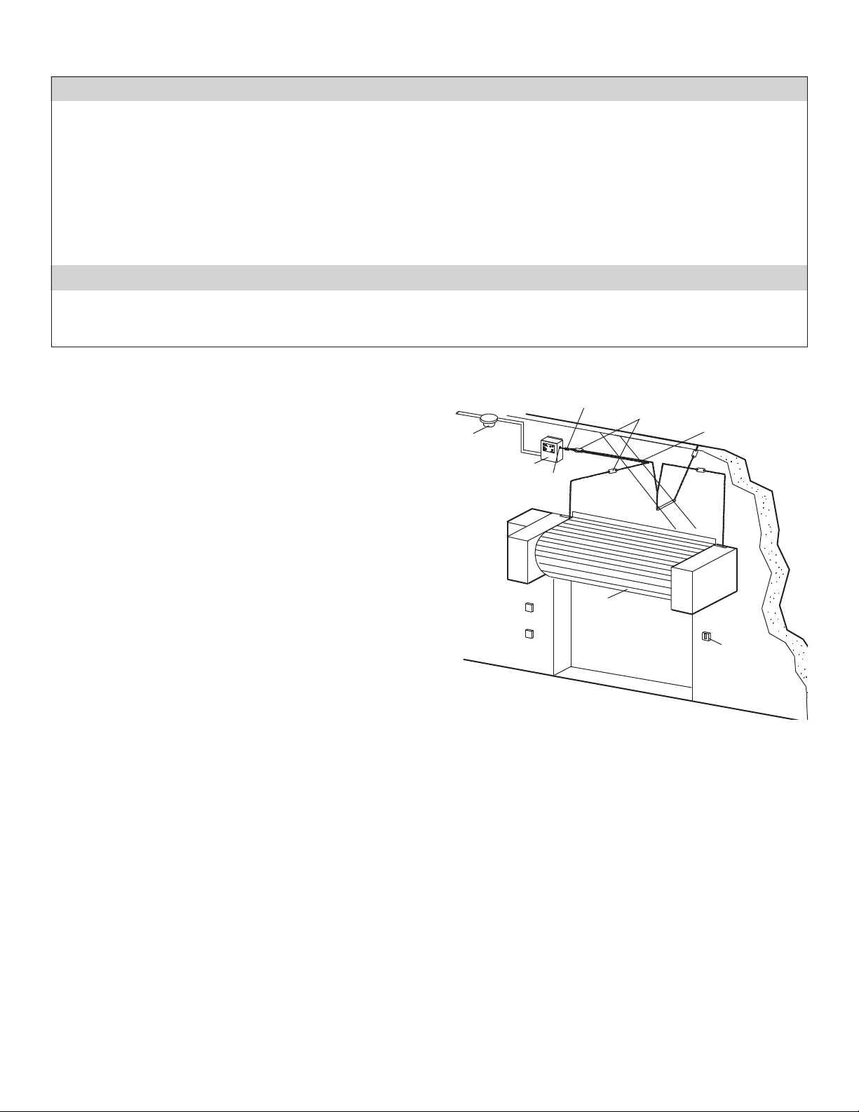
Smoke Detector
Releasing Unit
Turnbuckle
Annunciator
Chain
Fire Door
Chain
End Link
Fusible Links
Eyebolt
4
Installation
ENGLISH WARNINGS AT 50%
SPANISH WARNINGS AT 50%
FRENCH WARNINGS AT 50%
IMPORTANT INSTALLATION INSTRUCTIONS
TO REDUCE THE RISK OF SEVERE INJURY OR DEATH:
1. READ AND FOLLOW ALL INSTALLATION WARNINGS AND
INSTRUCTIONS.
2. NEVER connect release device to power source until instructed to
do so.
3. DO NOT use this device without fusible links installed.
4. Concrete anchors MUST be used if mounting release device into
masonry.
5. DO NOT exceed maximum pull rating of 40 lbs. on releasing
device.
Classification:
Releasing device as defined by Underwriters Laboratories.
Installation Requirements:
Intended for “Indoor Dry” locations; all wiring must be performed in
accordance with the most current version of NFPA 72 - National Fire
Alarm Code and the National Electric Code.
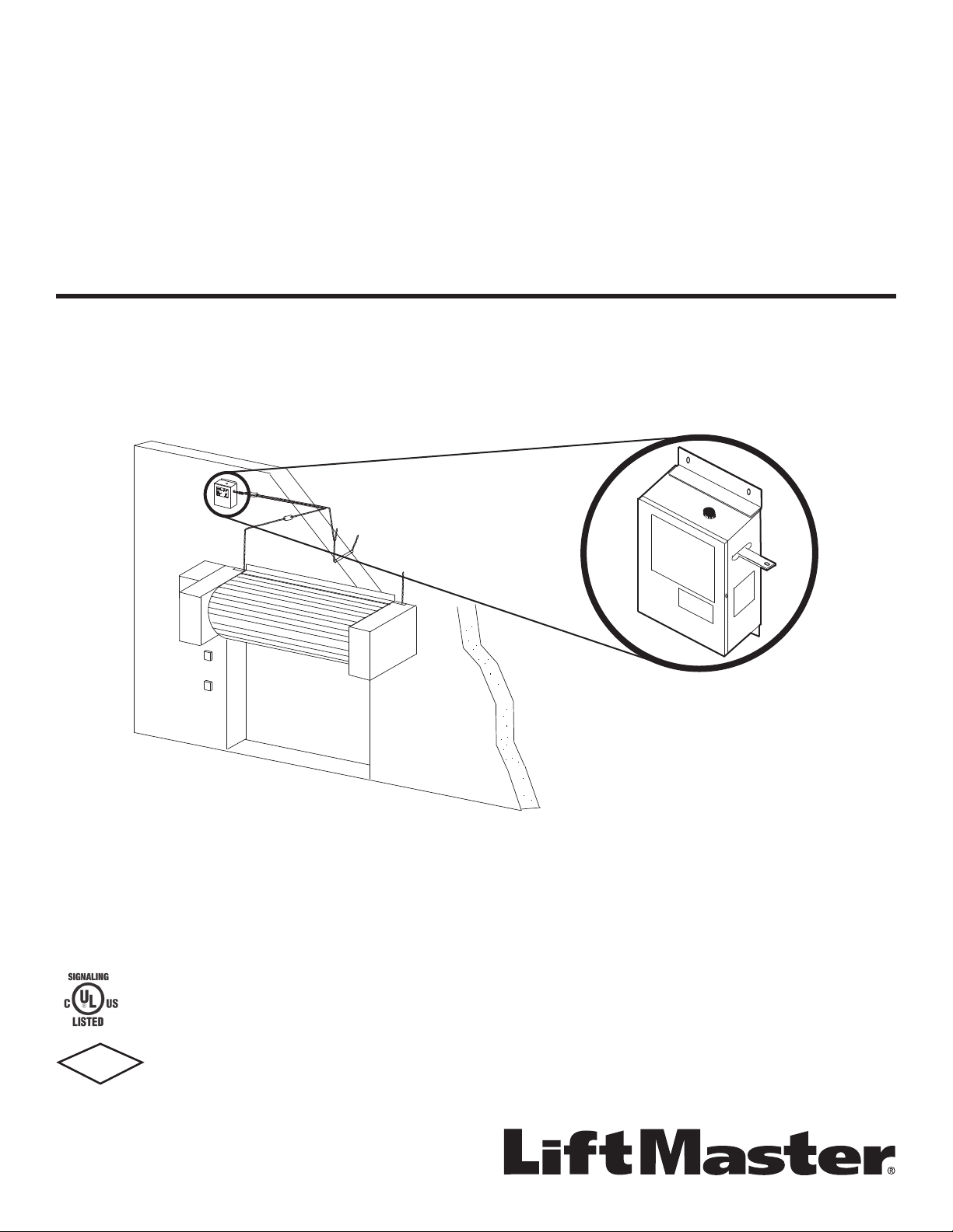
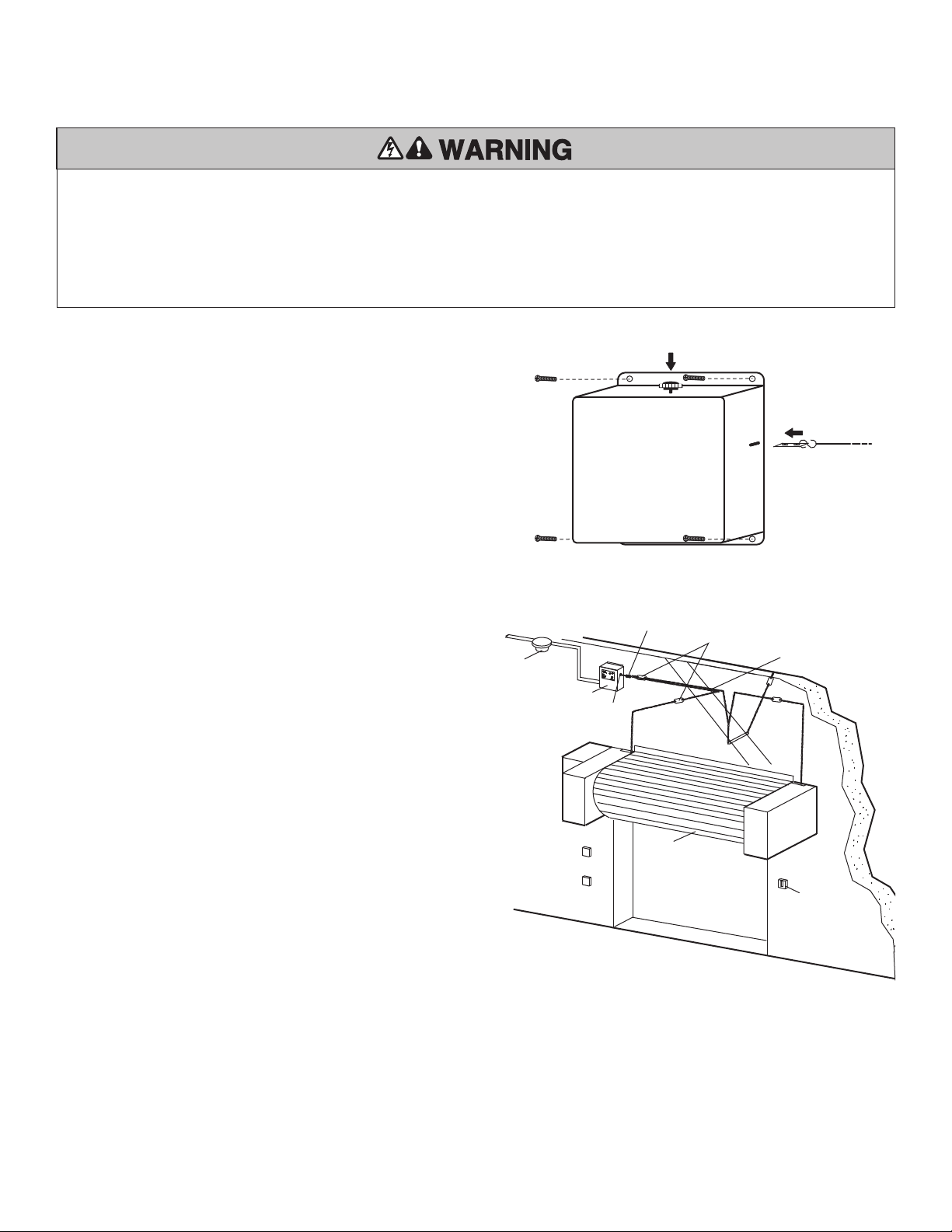
MOUNT THE RELEASE DEVICE
Installation procedures vary according to door types. Refer to door
manufacturer’s recommendation that applies to your door.
1. Mount the release device on a vertical surface with chain end link
exiting side of enclosure.
2. Secure the release device enclosure with fasteners (#10 is the
minimum size recommended). If installing in masonry, use
concrete anchors (not provided).
3. Install hardware (sash chain or 1/16" cable, eyebolts-hook,
fusible links, turnbuckles—not provided) according to door
manufacturer’s recommendations. NOTE: The end link direction
of pull must be perpendicular to the side of the release device
enclosure. Install an eyebolt a minimum distance of 12" from the
release device to adequately redirect sash chain pull.
4. Install end link by pressing mechanical reset to allow insertion of
end link. Push end link completely in and release mechanical reset
to latch end link.
5. Remove sash chain or cable slack by adjusting turnbuckle.
Smoke Detector
Releasing Unit
Turnbuckle
Annunciator
Chain
Fire Door
Chain
End Link
Fusible Links
Eyebolt
End Link
Mechanical Reset
Plunger
5
Wiring
WIRING INSTRUCTIONS
Verify wiring confi guration with that recommended by door
manufacturer for use of this product with specifi c door and accessories
being utilized. The use of 18 AWG wire is recommended.
1. Close fi re door prior to ANY wiring.
2. Turn off power supply sources for the release device as well as the
door operator, before beginning.
3. Verify voltage rating of release device to power source being
utilized. Voltage is indicated on the side of the unit. Verify that
power is disconnected before proceeding.
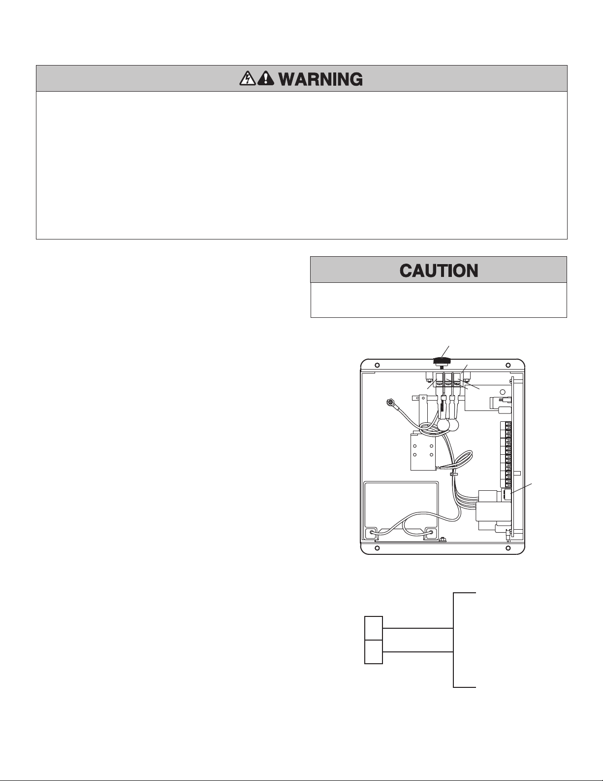
4. When powering the device from 120Vac line voltage, locate the
3-position terminal block mounted within the device enclosure.
Connect 120Vac (single phase) power source inputs to terminals
L1 (line) and L2 (neutral) of the terminal block (Figure 1). The third
position is used for earth ground.
5. When powering the device from 24Vac or 24Vdc power, connect
to terminal board positions 1 and 2 (Figure 2). Observe proper
polarity.
6. Do not connect line power or battery until all fi eld wiring is
complete per the following pages. The battery provides backup
power in the event of a loss of line voltage and prevents the release
of the fusible link assembly and the resulting door closure. A
pulsing sounder occurs when the battery is disconnected or when
replacement is required. The battery also provides power to the
various ancillary devices (i.e., smoke detectors, horn/strobes, etc.).
Figure 1
Figure 2
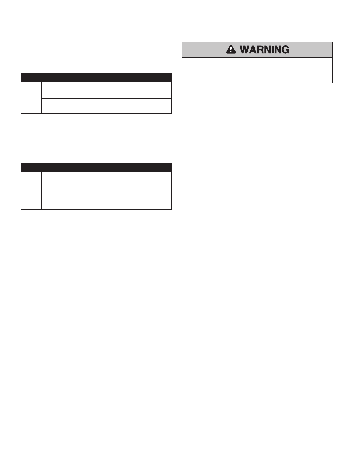
To reduce the risk of SEVERE INJURY or DEATH:
• ALL electrical connections MUST be made by a qualified
individual.
• Disconnect power at the fuse box BEFORE proceeding. Release
device MUST be properly grounded and connected in accordance
with local electrical codes.
• Installation of ALL wiring and connections, including Class 1 and
Class 2 circuits, shall be performed in accordance with, but not
limited to, the latest NFPA, UL and N.E.C. standards and codes. In
addition, ALL installations subject to Canadian standards shall be
performed in accordance with the Canadian Electrical Code, Part I,
with respect to wiring material type, wiring gauge related to power
capacity requirements and circuit length and wiring methods.
• ALL power wiring should be on a dedicated circuit and well
protected. The location of the power disconnect should be visible
and clearly labeled.
• ALL power and control wiring MUST be run in separate conduit.
• 120Vac should ONLY be attached to the 3-position terminal block
mounted within the enclosure.
• DO NOT disconnect battery or remove battery fuse while unit is
under power, the door will drop.
To prevent DAMAGE to the circuit board, ALL connections from
terminals 3 through 16 MUST be dry contact type.
Option
DIP Switch
Mechanical Reset
Plunger
L1L2
Power Strip
Ground
1
2
+
–
24Vac or 24Vdc
ENGLISH WARNINGS AT 50%
SPANISH WARNINGS AT 50%
FRENCH WARNINGS AT 50%
ENGLISH WARNINGS AT 50%
SPANISH WARNINGS AT 50%
FRENCH WARNINGS AT 50%
6
Wiring
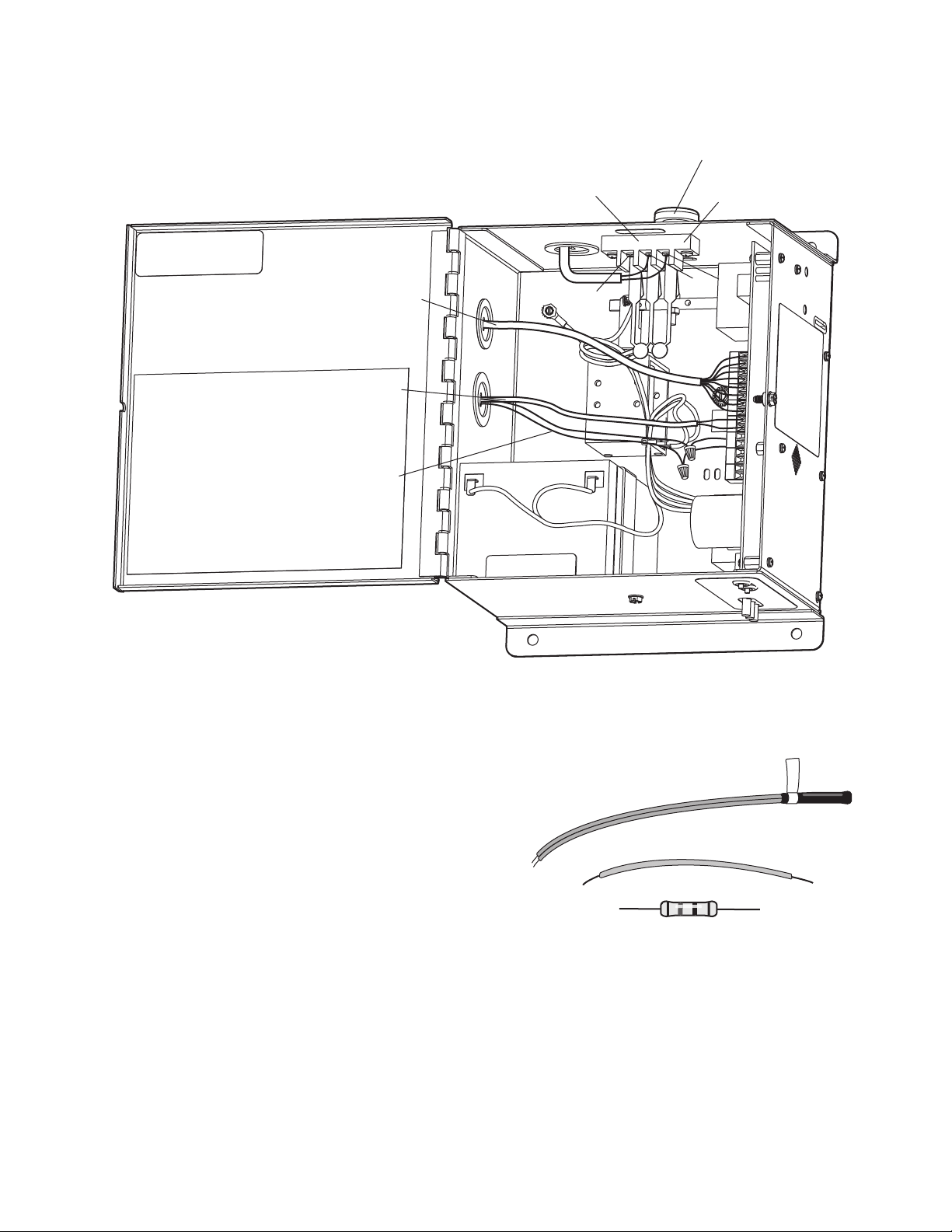
WIRE ROUTING
PARTS KIT
16 15 14 13 12 11 10 9 8 7 6 5 4 3 2 1
Mechanical Reset
Plunger
L1L2
Power Strip
Ground
High Voltage
Wiring
Low Voltage
Wiring
Annunciator
Wiring with
Sleeve
Voice Board
Wiring
Wire Jumper
LMEOLRES-10
10k Ohm Resistor
Refer to wiring section for proper application of these parts.
7
Wiring
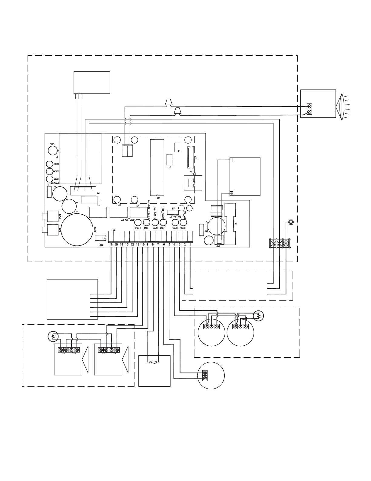
WIRING DIAGRAM
YE
WH
BK
BK
12 V, 4.5AH or
5.0AH Battery
2 Amp
maximum
current
Input Power
Auxiliary Common
Relay Connections
OR
120 Vac
Neutral
Ground
Trouble NO
Resistor
N. O.
Closed Door
Proximity
Switch (2)
(optional)
Trouble Com
Trouble NC
Alarm NO
Alarm Com
Alarm NC
Hot
+ 24V ac/dc
NC
COM
3 Amp, 250 V,
3AG Slo-Blo
+ Strobe
+ Horn
– Strobe
+ In
+ Out
– In/Out
+ In
+ Out
– In/Out
– Horn
+ Strobe
+ Horn
– Strobe
– Horn
L1
L2
L3
RD
GR
GY
Replace batteries every 2 years. Field wiring shall consist of 22-18 AWG wiring.
Use only 250Vac, 3 Amp, 3 AG, Slo-Blo fuses.
1. Supervised, power limited circuit, 20 Ohm maximum line impedance.
2. Unsupervised power limited circuit, 20 Ohm maximum line impedance.
3. Maximum of 4 Class B Style A detectors.
4. Maximum of 2 Class B Style W notification appliances. 0.5 Amp at 24 Vdc maximum.
Supervised non-power limited circuit.
2-Wire Detector
Initiation Loop (1) (3)
Keep 10 kOhm resistor
between 3 & 4 if unused
EOL 10 kOhm
Annunciator
Loop (4)
10 kOhm
EOL Resistor
Normally Closed
Initiation Loop (1) (3)
Keep jumper between
5 & 6 if unused.
External power required.
Solenoid
Speaker- Voice
board model only
+ Speaker
- Speaker
PU
YE
Keep 10 kOhm
EOL resistor
between 9 & 10
if unused
8
– IN/OUT
+ OUT
+ IN
– IN/OUT
+ OUT
+ IN
3
4
10k Ohm @1/2 watt
Supervisory Resistor
(LMEOLRES-10)
NOTE: Follow this method
of attachment when using
LM2W-B, LM2WT-B, or
other 2-wire 24Vdc smoke
detectors.
24Vdc Power from
Terminal Strip
Wiring
(+)
(–)
(–)
(+)
(–)
(+)
(–)
(+)
3
4
Power from
Control Panel
NOTE: Follow this method of attachment when using LM4W-B,
LM4WT-B, or other N/O 4-wire smoke detectors.
10k Ohm @1/2 watt
Supervisory Resistor
(LMEOLRES-10)
Terminal Strip
LMEOLR1224
12/24 Vdc EOL
Relay
IMPORTANT: When using 4-wire smoke detectors with this device,
the smoke detectors must be powered from a source other than the
release device, such as an approved UL1481 regulated power
supply providing battery backup support.
Alarm
Contacts
Style A
(N/O)
(–)
(+)
3
4
COM
NO
– IN/OUT
+ OUT
+ IN
COM
NO
– IN/OUT
+ OUT
+ IN
10k Ohm @1/2 watt
Supervisory Resistor
(LMEOLRES-10)
Terminal Strip
Power from
Control Panel
LMEOLR1224
12/24 Vdc EOL
Relay
NOTE: Follow this method of attachment when using LM4W-B,
LM4WT-B, or other N/O 4-wire smoke detectors.
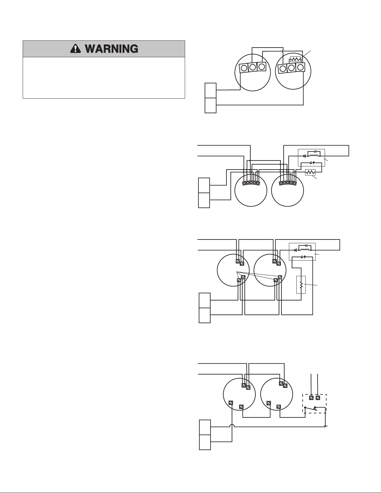
CONNECTIONS OF INITIATING DEVICES AND ACCESSORIES
A maximum of 4 smoke detectors may be installed with this device.
Refer to NFPA 72 and NFPA 80 for instructions concerning proper
placement and detection coverage. End-of-line devices must be
installed for supervision of electrical power to 4-wire smoke detector.
When using 4-wire smoke detectors with this device, electrical
supervision must be provided by means of a UL/ULC listed end-of-line
relay.
NOTE: For low voltage wiring #18 AWG is recommended.
Normally Open “2-Wire,” Class B Style A Initiating Devices
Connect wiring from N/O initiating device loop to positions 3 and 4.
Place the supervisory resistor (LMEOLRES-10) contained within the
accessory pack. (Figure 3). Observe proper polarity, 3 (+), 4 (–) when
attaching to the release device’s terminal board.
NOTE: Make certain that the Wire Jumper is placed between positions 5
and 6.
This option is a supervised, current-limited circuit.
OR
Normally Open “4-Wire,” Class B Style A Initiating Devices
Connect wiring from N/O 4-Wire initiating device loop to positions 3
and 4, making sure an end-of-line supervisory resistor (LMEOLRES-10)
is installed as shown in Figure 4 or 5, depending upon the type of
smoke detector being used. Observe proper polarity, 3 (+), 4 (–) when
attaching to the release device’s terminal board.
NOTE: Make certain that the Wire Jumper is placed between positions 5
and 6. This option is a supervised, current-limited circuit.
OR
Normally Closed “4-Wire,” Class B Style A Initiating Devices
Connect wiring from N/C 4-Wire initiating device loop to positions 5
and 6 (Figure 6). This option is a supervised, current-limited circuit.
NOTE: Make certain that the 10k ohm resistor is placed between
positions 3 and 4.
NOTE: End-of-line devices must be installed adjacent and after the last
initiating device. Initiating device loops are supervised and cannot be
direct series or paralleled between multiple release devices or shared
with other alarm equipment. For proper wiring configurations from
multiple smoke detectors or signaling for simultaneous closure on
multiple doors, call technical support, 1-888-528-7870. Incorrect wiring
between devices may cause damage to the release control circuit and
void warranty.
OR
Relay Module Installation as described on the following page.
To prevent possible SERIOUS INJURY or DEATH:
• End-of-line devices MUST be installed for supervision of electrical
power to 4-wire smoke detector.
• DO NOT install this device on a motorized door without an electric
safety edge.
Figure 3
Figure 4
Figure 5
Figure 6
(–)
(–)
(–)
(+)
(+)
(+)
(–)
(+)
5
6
Power from
Control Panel
Terminal Strip
LMEOLR1224
12/24 Vdc EOL
Relay
IMPORTANT: When using 4-wire smoke detectors with this
device, the smoke detectors must be powered from a source
other than the release device, such as an approved UL1481
regulated power supply providing battery backup support.
Power from
Control Panel
Purple
N/C N/C
C
C
NOTE: Generic version of a N/C
4-wire smoke detector is shown.
ENGLISH WARNINGS AT 50%
SPANISH WARNINGS AT 50%
FRENCH WARNINGS AT 50%
9
11
12
13
14
15
16
N/C Alarm Relay Output
Common
N/O Alarm Relay Output
N/C Trouble Output
Trouble Common
N/O Trouble Output
Make all necessary
connections to the
Fire Alarm Panel as
required by the project
specifications and the
Authority Having
Jurisdiction
Wiring
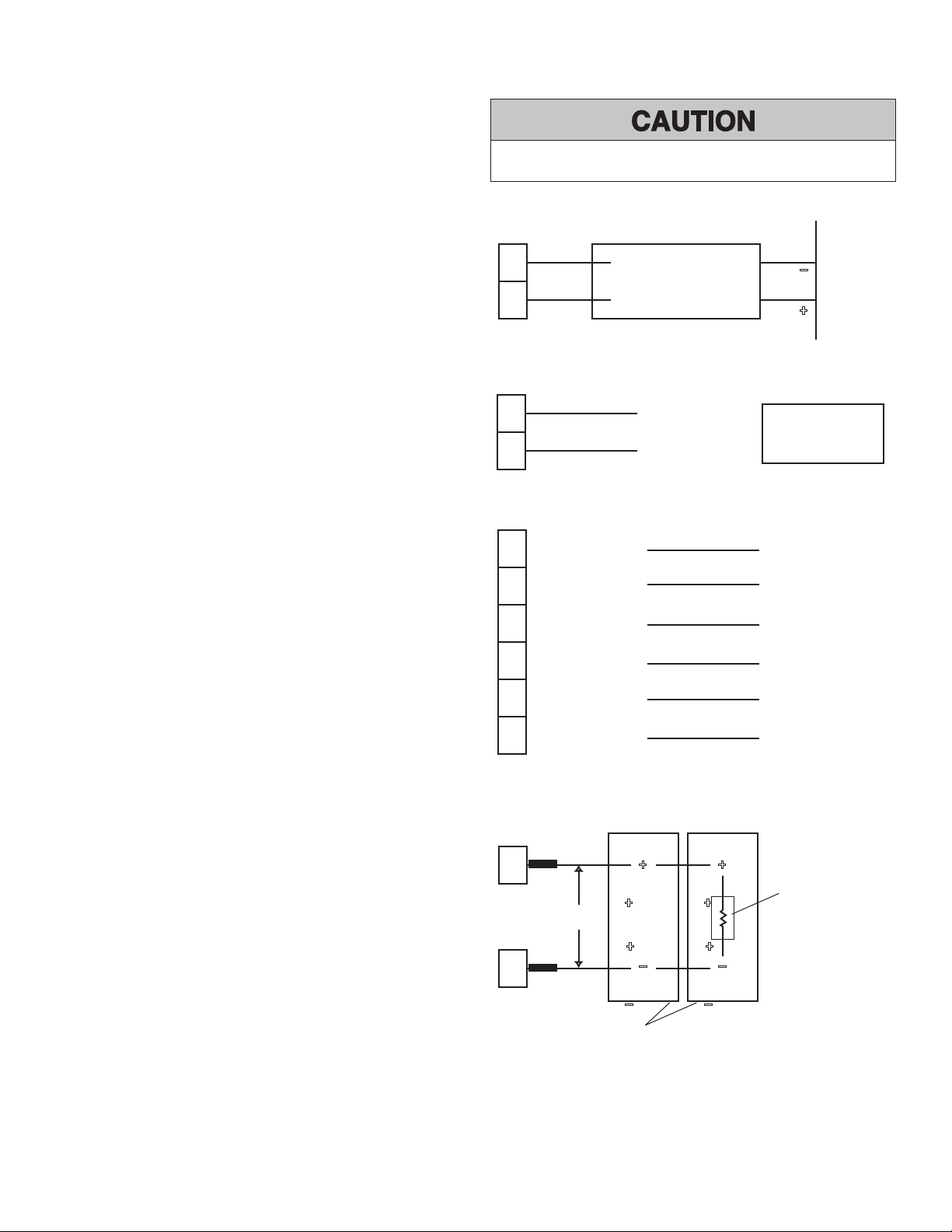
OPTIONAL CONNECTIONS
CLOSE DOOR DETECTION OPTION
Connect wiring from N/O electrical loop, using a proximity switch or
other similar device with dry contacts, to 7 and 8 (Figure 8). The switch
should be placed to engage when the door is in the closed position
and so that it will toggle states from its N/O condition (switch closed
when door is closed) to a closed condition indicating that the door
edge has made contact with desired down position. When the switch
is closed by contact from the door, the release device will not activate
on alarm, thereby eliminating nuisance gravity drops through the
inadvertent release of the fusible link assembly. This option only works
as long as power is available to unit. Fail-safe operation is maintained
under all operating conditions, and if power is not available to the
unit, the fusible link assembly will be released. This is a power-limited,
unsupervised circuit. This proximity switch must be mounted in the
same room as the release device.
RELAY AND TROUBLE OUTPUTS OPTION
Connect wiring from the Alarm Relay Outputs (#11 N/C or #13 N/O
and #12 Common) to the appropriate inputs on the Fire Alarm Control
Panel to provide a signal at the panel when the release device is in an
alarm state. Connect wiring from the Trouble Relay Outputs (#14 N/C or
#16 N/O and #15 Common) to the appropriate inputs on the Fire Alarm
Control Panel to provide a signal at the panel that the release device is
in a trouble state (Figure 9). If these features are desired, coordinate the
interconnection between the Release Device and the Fire Alarm Control
Panel with the fire alarm installer.
ANNUNCIATOR OPTION
To power one or two (maximum) horn/strobes or similar annunciators,
connect wiring to terminals 9 and 10 (Figure 10). Route wires through
the non-conductive sleeving (provided) covering any exposed bare
wires. Maximum distance of wire run within conduit not to exceed 20'
total. This is a supervised, non power-limited circuit.
NOTE: If installing two visual annunciators, they must be installed on
opposite sides of wall. If unused, place 10k Ohm Resistor between
positions 9 and 10.
CONNECTIONS OF INITIATING DEVICES AND ACCESSORIES (cont’d)
Relay Module Installation
In lieu of smoke detectors, the release device may be put into alarm by
the fire alarm control panel. Most commonly, a relay module is used as
an interface between the fire alarm control panel and the release device.
The relay module must provide Form C dry contacts for connection to
the appropriate terminals on the release device (Figure 7).
NOTE: When choosing a relay module to activate the release device in
an alarm condition, always select one that provides Form C dry contact
relays. Do not use any relay module providing or passing any (control)
voltage through the contacts into the release device. The passage of
voltage through such a relay module into the release device will cause
problems with the operation of the device and may damage the device’s
terminals and/or circuit board. Make certain that the 10k ohm resistor is
placed between positions 3 and 4.
Figure 7
Figure 8
Figure 9
Figure 10
To prevent DAMAGE to the circuit board, ALL connections from
terminals 3 through 16 MUST be dry contact type.
5
6
–
+
Fire Alarm
Control Panel
Normally Closed
Common
Terminal Strip
7
8
Attach to Common on
N/O Proximity Switch
Attach to N/O Position
on Proximity Switch
Proximity Switch Part
No. LM56A
10
–
–
9
+
+
Horn/Strobe Annunciator
LMHS24R
Horn/Strobe
Horn/Strobe
NOTE: A maximum of two annunciators may be installed in this manner.
10k Ohm @ 1/2 watt
Supervisory Resistor
(LMEOLRES-10)
Terminal Strip
Non-conductive sleeve
ENGLISH WARNINGS AT 50%
SPANISH WARNINGS AT 50%
FRENCH WARNINGS AT 50%
10
Wiring
OPTIONAL CONNECTIONS (cont’d)
VOICE BOARD OPTION
The voice board provides one of two verbal warnings that the fire door
is closing. Typically, depending on the length of the delay chosen on the
release device, a warning tone will occur prior to the message, which
is approximately 10 seconds in length (for example, a 20 second delay
setting on the release device will result in a 10 second warning tone
followed by the verbal warning message). There are two messages that
may be selected:
Message 1: Warning tone followed by the message, “Warning! An
emergency condition exists and this fire door is about to close;
please remove any obstructions from its path and stand clear.”
Message 2: Warning tone followed by the message, “Warning!
This fire door will close in 10 seconds... 5 seconds... the fire door
is now closing; please remove any obstructions from its path and
stand clear.”
The release device has an 4-position DIP Switch mounted on the
circuit board, and the switch at position #3 permits selection of either
message. In the “ON” position, Message 1 is activated; in the “OFF”
position, Message 2 is activated (Figure 12).
The voice board can drive up to two 70.7V speakers (Model LMSP24R)
or speaker inputs to speaker strobes (Model LMSS24R). Maximum
delivered power is 5 watts.
A potentiometer (VR1) is mounted on the board and rotation
counterclockwise increases the volume (clockwise to decrease volume)
(Figure 11).
DIP SWITCH SELECTION
The release device will provide a factory default delay of 10 seconds (to
minimize nuisance alarms) before releasing the fusible link chain upon
alarm or power loss. A 4-position DIP Switch found on the PC board
within the release device can be used to adjust the length of the delay to
one of four preset delays.
The optional delay settings are as follows:
NOTE: Set all DIP switch options before applying power to the system.
1 2
10 Seconds Off Off
20 Seconds Off On
30 Seconds On Off
60 Seconds On On
Delay Settings Switch Position
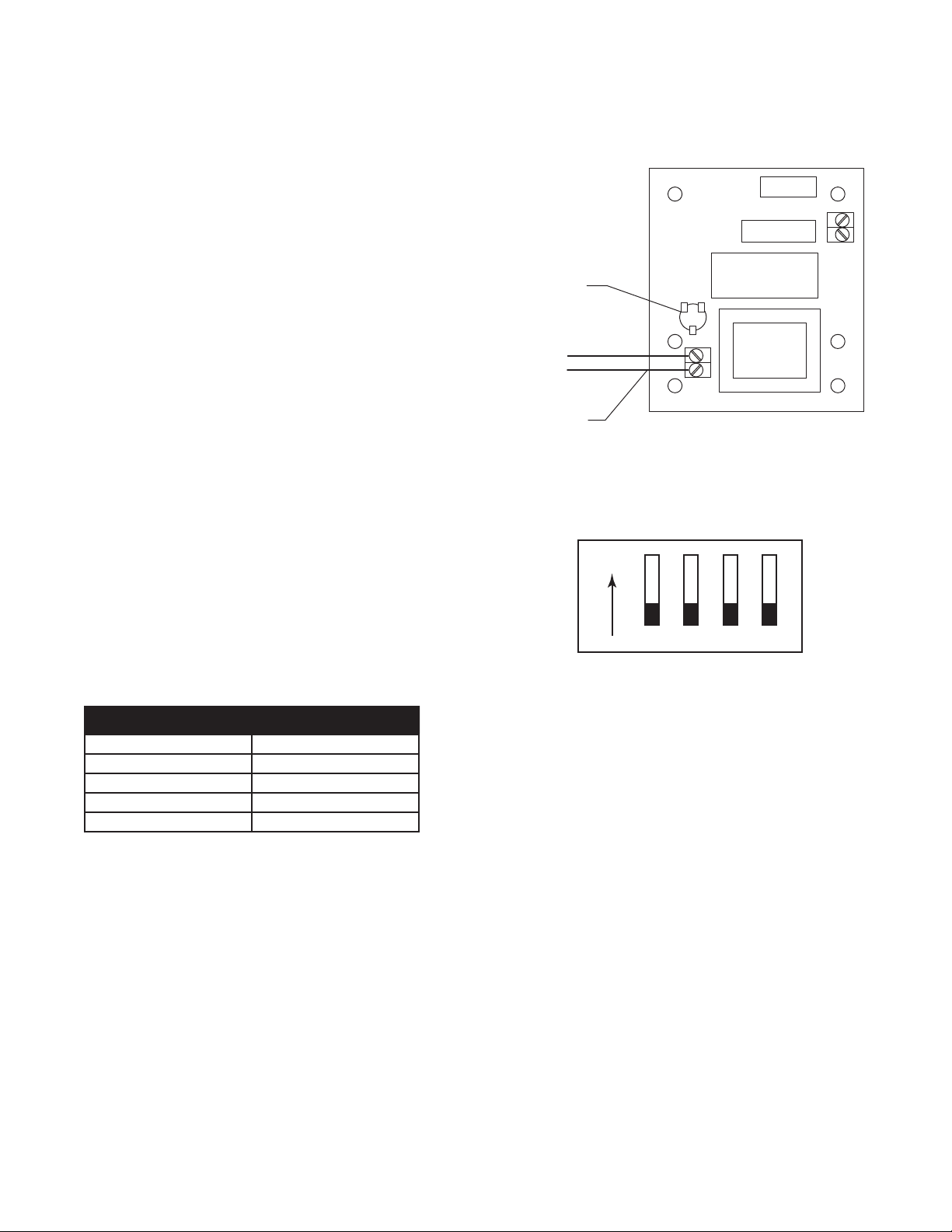
Figure 11
Figure 12
Wire to Speaker
Volume Control
CCW for Max
1 2 3 4
ON
NOTE: Position 4 is unused and should remain in the OFF position.
Position 3 is used to select one of the two available voice messages.
Factory default setting of 10 seconds shown.
11
Testing
Figure 13
TEST PROCEDURES
TO BE PERFORMED BY FACTORY AUTHORIZED PERSONNEL ONLY!
CLEAR FIRE DOOR OPENING AND PROHIBIT TRAFFIC THROUGH
DOOR OPENING WHILE TESTING!
Testing does not affect normal operation of alarm system when
connected to release device/control panel. Testing of the release device
is independent of, and shall in no way be interpreted as an alternative
method of, testing of a central fire alarm system, motorized operator
and/or any other system component employed on the fire door or
counter fire door installation. Complete testing and normal operation
can only be accomplished with power applied to unit.
Door must be in open position with power applied to unit to begin
testing. The following procedures describe testing of all options. Verify
options ordered and installed with unit. All tests may not apply. Refer
to Figure 13 for location of all the LEDs and switches mentioned in this
section.
INITIAL POWER UP
1. Connect black battery wire to the black terminal on the battery.
Connect the red battery wire to the red terminal.
2. Apply line power to the unit.
3. Power LED (red) and battery LED (green) will be lit on the bottom
of the release device (Figure 13).
MECHANICAL RELEASE
1. Depress and continue to hold test button on side of release device.
Unit will beep as delay expires. After the selected delay expires,
the device will release the end link and allow door to drop. Release
test button.
2. Reset the door per door manufacturer’s instructions. Raise door
and then reset the release device by pushing downward on the
mechanical reset button at the top of the device. Fully insert the
end link through the side opening on the device and release the
reset button in order to latch end link.
CLOSE DOOR DETECTION (OPTIONAL)
1. Using the chain hoist or motor operator, lower the door to fully
closed position.
2. Verify that Release Disabled LED (yellow) is lit indicating door
closure. Depress and continue to hold test button on side of
release device for 10 seconds. Close Door Detection logic will
prohibit the release device from energizing and releasing the end
link. Reset the test button (Figure 13).
3. Raise door to fully open position.
SUSPENSION OF POWER
1. Make sure door is in fully open position. Turn off all power to
release device and disconnect battery. Immediately upon loss of
power (line voltage and battery backup) to the release device, a
mechanical release will be initiated.
2. Reset the door per door manufacturer’s instructions. Raise the
door and then reset the release device by pushing downward on
the Mechanical Reset Plunger at the top of the device. Fully insert
the end link through the side opening on the device and release
the Mechanical Reset Plunger in order to latch end link. Press the
“Reset” button on the device to reset the alarm loop.
After completing all tests, make sure the door is in it’s normal position
(open or closed) and all power required for normal operation is restored
to unit. The release device is designed to operate with power applied.
NOTE: Testing shall be performed and witnessed for proper operation.
To prevent possible SERIOUS INJURY or DEATH:
• Clear fire door opening and prohibit ALL traffic through door
opening while testing.
• Test every 90 days to assure proper operation of release device.
• Disconnecting the battery may trigger a release of the plunger
creating a mechanical release.
ENGLISH WARNINGS AT 50%
SPANISH WARNINGS AT 50%
FRENCH WARNINGS AT 50%
Front of Release Device
End Link
Mechanical Reset Plunger
Test Button
Electronic
Reset Button
Bottom of Release Device
Yellow LED (Release Disabled)
Red LED (Line Power Present)
Green LED (Battery Backup Power Present)
12
Troubleshooting
OPERATIONAL CHECKLIST
POWER
Is the red LED, labeled “Power,” located on the bottom of the enclosure
lit?
CHECK THE ALARM
Are the alarm (smoke detection) inputs correct? If not, the release
device will not release the fusible link assembly in a fire condition.
Conversely, the release device will always release the fusible link
assembly when powered or reset.
To prevent possible SERIOUS INJURY or DEATH:
• Clear fire door opening and prohibit ALL traffic through door
opening while trouble shooting.
ENGLISH WARNINGS AT 50%
SPANISH WARNINGS AT 50%
FRENCH WARNINGS AT 50%
CHECK THE CLOSE DOOR DETECTION
Is the Yellow LED on the bottom of the enclosure lit? If lit, the close
limit detection input is active, the devise is disabled and will not
perform a mechanical release.
CHECK THE BATTERY CONNECTIONS
Is the Green LED on the bottom of the enclosure lit? If so, the battery
is connected properly. If the LED does not light, the battery is not
functioning properly and a trouble sounder will annunciate. Check the
following:
1. Are the battery leads properly connected or do the leads have a
defective connector?
2. Do the battery connections observe correct polarity — Red (+)
and Black (–)?
3. Is the battery discharged? If so, allow 10 minutes for the battery
management system to recharge the battery. If the sounder does
not stop after this time, then the battery needs to be replaced.
Refer to the “Replacement Parts and Accessories” section of this
manual for ordering instructions.
Battery Performance Inconsistencies - Does the unit go into alarm
and release the fusible link as soon as power is applied? If so, then
check the wiring and connections on the smoke detector loop, focusing
especially on the presence and the correct placement of the end-of-line
resistor. Also, if N/O smoke detectors are being used, make certain
that the Wire Jumper between positions 5 and 6 on the release device’s
terminal strip is in place.
Is the Red LED Lit?
Yes Move on.
No Check power connections per Wiring Diagram.
Check voltage; voltage should be 120Vac, 24 Vac or 24Vdc
connected as part of the wiring diagram.
Are the Alarm Inputs correct?
Yes Move on.
No Check that it is a dry contact input. There should not be any
voltage on the alarm lines when they are disconnected from
the unit.
Verify that all wiring is per manufacturers’ instructions.
13
Troubleshooting
CIRCUIT BOARD DIAGNOSTIC LEDS
View diagnostic LEDs present on the circuit board located behind the terminal block (See Wiring Diagram).
Refer to the table below for the status LED indications.
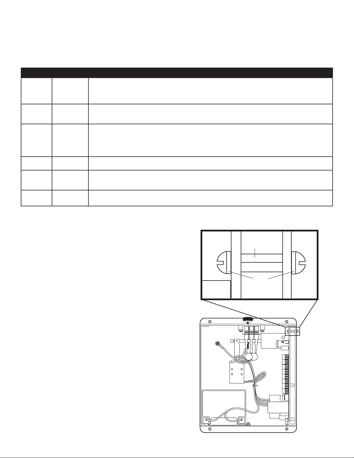
GROUND FAULT ERROR
When a separate device (fire alarm control panel) with its own ground
fault is introduced, the potential for the release device to recognize a
“double-ground fault” error exists. In the event that this Ground Fault
error occurs, the ground fault light on the board will illuminate and the
system will begin beeping.
TO CORRECT THE GROUND FAULT ERROR:
1. Disconnect power to the unit, both line and battery power.
NOTE: Mechanical release will be initiated upon loss of power.
2. Locate the aluminum standoff that is part of the grounding system
in the unit (Figure 14).
3. Carefully remove the two screws holding the aluminum standoff in
place.
4. Once the aluminum standoff has been removed, reconnect line
voltage and battery wires.
If the Ground Fault error has been cleared, the release device will
operate as intended. Auxiliary fire alarm devices attached to the device
are now providing the ground fault protection monitoring.
If the Ground Fault error remains, proceed with regular troubleshooting.
Disconnect accessories one at a time checking if the Ground Fault
error clears.
N/O Detector
Trouble
Yellow (LED 6) If lit, indicates a trouble condition (open) within the N/O 2-wire (or 4-wire) smoke detector loop (emanating from
terminal board positions 3 and 4), resulting from either incorrect wiring or incorrect placement of the end-of-line
resistor, and the smoke detector loop is inactive. Refer to the Smoke Detector Installation section of this manual
for correct wiring instructions (Figures 3-5).
N/O Detector
Alarm
Red (LED 5) If lit, indicates that the N/O 2-wire (or 4-wire) smoke detector loop (emanating from terminal board positions 3 and
4) is in alarm. When lit during testing, press the Auxiliary Reset Button at the bottom of the release device to reset
the loop (Figures 3-5).
N/C Detector
Trouble
Red (LED 4) If lit, indicates an open circuit within the N/C 4-wire smoke detector loop (emanating from terminal board positions
5 and 6), resulting from either incorrect wiring or incorrect placement of the end-of-line relay or the detector(s)
are in alarm. If in alarm, cycle power off and then on to the smoke detectors to reset, then depress the auxiliary
reset button to reset the release device. Refer to the Smoke Detector Installation section of this manual for correct
wiring instructions (Figures 6 and 7).
Close Door
Detection
Green (LED 2) If lit, indicates that the fire door or shutter is closed and activating the proximity switch. If not lit, refer to the Close
Door Detection section of this manual for correct wiring instructions (Figure 8).
Annunciator
Trouble
Yellow (LED 9) If lit, indicates a trouble condition (open) within the annunciator loop (emanating from terminal board positions
9 and 10), resulting from either incorrect wiring or incorrect placement of the end-of-line resistor. Refer to the
Annunciator section of this manual for correct wiring instructions (Figure 10).
Ground Fault Yellow (LED 3) If lit, indicates that one of the ancillary devices/loops (smoke detector, annunciator, etc.) is not grounded properly,
and a short to earth ground exists.
LED LED Color Description
Screws
Aluminum
Standoff
Front View
Figure 14
14
ENCLOSURE MOUNTED LEDS STATUS INDICATORS
Battery Green If the Green LED is lit, then the battery is connected
properly and charged above the minimum acceptable level.
If the LED does not light, check that the leads are
connected to the battery as shown on the wiring
diagram.
Disable Yellow The Yellow LED will light when the door reaches the close
limit and activates a proximity switch attached to terminal
positions 7 and 8 on the release device. This configuration
results in the device not releasing the fusible link assembly
in alarm or power loss situations and should only be used
when the fire door is kept in a constant closed position.
If the LED does not light when the door reaches the
close door detection and activates the proximity
switch, then check that the proximity switch has
been activated and that the switch is set to normally
open (N.O.). Check to make certain that the switch is
attached to terminal positions 7 and 8 on the release
device.
Power Red If the Red LED is lit, then the line power is connected and
switched “on.”
If the LED does not light when power is applied, check
that power is connected as described in the installation
manual electrical connections.
LED Label LED Color Description Action Required
Maintenance
MAINTENANCE REQUIREMENTS
The release device has no scheduled maintenance requirements. The
unit has been designed and tested for use in dry, indoor locations.
Testing of the unit at least once every 90 days is recommended, but
test intervals shall ultimately be subject to criteria established by the
Authority Having Jurisdiction (AHJ).
FUSE REPLACEMENT PROCEDURE AND REPAIR PARTS
One serviceable fuse, a 3 Amp, 3AG, slo-blo fuse, is required for proper
operation and protection of the circuit board. The release device is
shipped with the fuse in place and two replacement fuses are provided
in a separate parts bag. The fuse is located on the circuit board near the
battery cable connection.
For replacement parts refer to Accessory and Replacement Parts page.
BATTERY MAINTENANCE/TESTING
No maintenance or testing is required for the battery. An audible
warning tone, generated by the trouble annunciator mounted to the side
of the release device, will sound when the battery is approaching the
minimum operating threshold. This indicates the need to replace the
battery. It is recommended that the battery be replaced every 2 years.
For replacement parts refer to Accessory and Replacement Parts page.
BATTERY DISPOSAL
Spent batteries must be treated as hazardous waste and disposed of in
accordance with State, Local and Federal Regulations.
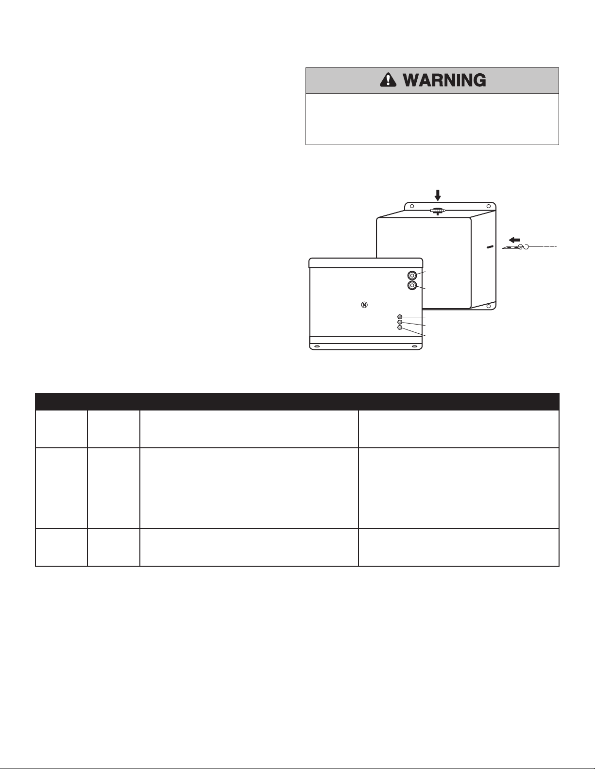
To prevent possible SERIOUS INJURY or DEATH:
• Stand clear of path of door.
• Disconnect ALL electrical and battery power BEFORE performing
maintenance.
ENGLISH WARNINGS AT 50%
SPANISH WARNINGS AT 50%
FRENCH WARNINGS AT 50%
Front of Release Device
End Link
Mechanical Reset Plunger
Test Button
Electronic
Reset Button
Bottom of Release Device
Yellow LED (Release Disabled)
Red LED (Line Power Present)
Green LED (Battery Backup Power Present)
Figure 15

15
Accessories and Replacement Parts
HOW TO ORDER REPAIR PARTS
Item Part # Description Item Part # Description
1 LM8100 Smoke Detector - 120V Photo 13 LMSS24R Speaker Strobe - 24Vdc
2 LM8100T Smoke Detector - 120V Photo with Thermal 14 LMS24R Strobe - 24Vdc
3 LM8100I Smoke Detector - 120V Ion 15 LMHS24R Horn/Strobe - 24Vdc
4 LM2WB Smoke Detector - 12/24Vdc 2-Wire Photo 16 LMH24R Horn - 24Vdc
5 LM2WTB Smoke Detector - 12/24Vdc 2-Wire Photo with Thermal 17 LMPSTR1V75ADA Speaker Strobe - 120Vac
6 LM4WB Smoke Detector - 12/24Vdc 4-Wire Photo 18 LML1V750ADA Strobe - 120Vac
7 LM4WTB Smoke Detector - 12/24Vdc 4-Wire Photo with Thermal
and Form C Relay
19 LMHS1V75ADA Horn/Strobe - 120Vac
8 LM1424 Smoke Detector - 24Vdc Ion 20 LMEH120ADA Horn - 120Vac
9 LM1412 Smoke Detector - 12Vdc Ion 21 LMSP24R Speaker 8"
10 LMTH135 Heat Detector - 135 Degree Fixed Temperature 22 LMEOLR1224 End-of-Line Relay - 12/24Vdc
11 LMTH194 Heat Detector - 194 Degree Fixed Temperature 23 LMEOLR120 End-of-Line Relay - 120Vac
12 LMEH1224ADA Horn - 12/24Vdc
Item Part # Description
1 LMRK Reset Knob
2 LMELH End Link
3 LM2AG3AMP Fuse - 3Amp
4 LMEOLRES10 End-of-Line Resistor, 10 kOhm
5 LM4AH12 Battery
Accessories
Replacement Parts
NOTE: Certain accessories above will require a separate power source. Refer to
product manual.
OUR LARGE SERVICE ORGANIZATION SPANS AMERICA
Installation and service information
call our TOLL FREE number:
1-800-528-2806

01-32051G
Issue Date: 2017
© 2017, LiftMaster
All Rights Reserved
Appendix
Model No. Description
System Sensor
Model No.
Chemtronics
Model No.
Edwards System Technology
(EST) Model No.
LMTH135 135 Degree Fixed Temperature #5603 #603 #283B-PL
LMTH194 194 Degree Fixed Temperature #5604 #604 #284B-PL
Model No. Description System Sensor Model No.
LMSS24R 24Vdc Speaker Strobe, Red, Fire SP2R1224MC, SPSRL
LMS24R 24Vdc Strobe, Red, Fire S1224MC, SRL
LMHS24R 24Vdc Horn/Strobe, Red, Fire, 2W P1224MC, P2R, P2RL
LMH24R 24Vdc Horn, Red H12/24, HRL
LMSP24R Speaker, Red SP201R, SPRL
Model No. Description
System Sensor
Model No.
Space Age
Electronics No. LiftMaster No.
LMEOLRES10 10 kOhm End-of-Line Resistor LMEOLRES-10
LMEOLR1224 End-of-Line Relay EOLR-1
LMEOLR120 End-of-Line Relay PAM-1
Model No. Description System Sensor Model No.
LM2WB 24Vdc 2-Wire Photo 2W-B
LM2WTB 24Vdc 2-Wire Photo with Thermal 2WT-B
LM4WB 24Vdc 4-Wire Photo 4W-B
LM4WTB 24Vdc 4-Wire Photo with Thermal & Form C Relay 4WT-B
Heat Detectors
End-of-Line Device
Notification Devices
Smoke Detectors
NOTE: Certain accessories above will require a separate power source. Refer to product manual.
ACCESSORY COMPATIBILITY GUIDE