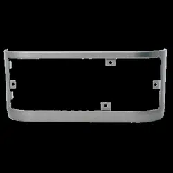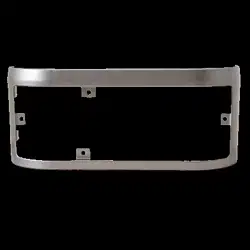
Main Enclosure Replacement
Repair parts 041-0190-000, 041-0191-000, and 041-0207-000
Instructions
You will need:
• 1/4" magnetic nut driver
• Long-nosed pliers
• 5/16" long-shafted magnetic nut driver and socket
• Flathead screwdriver
The images throughout this manual are for reference only and your
product may look different.
1. Unplug garage door opener and unplug battery (if necessary)
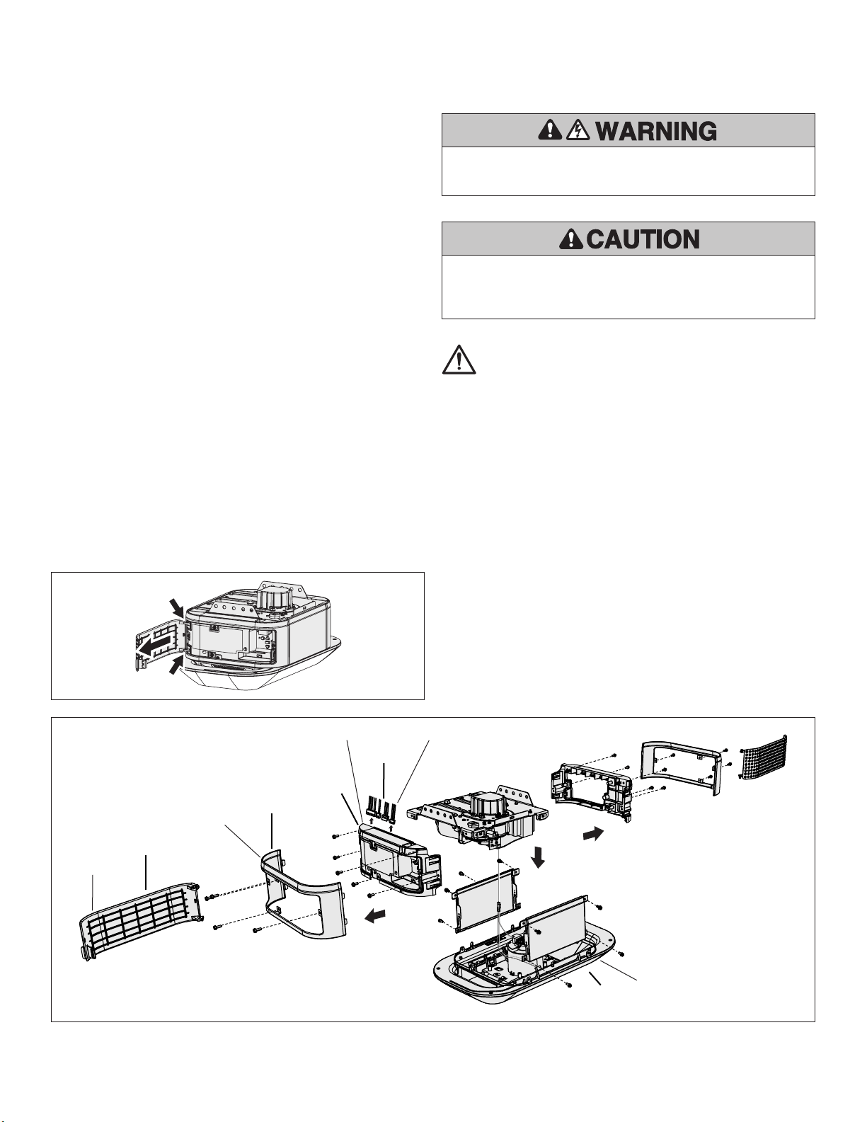
2. Remove the plastic doors from both sides and place in a safe spot
(Figure A)
3. Remove the end panel covers from both sides and place in a safe spot
(Figure B, Item B)
4. Take 4 or 6 screws out of sides depending on model
5. Remove Integrated LED Light Module (Figure B, Item E)
6. Unplug Integrated LED Light Module (and camera if necessary) and
place in a safe spot
7. Remove 4 screws from logic board side end panel (non-pointy screws)
(Figure B, Item C)
8. Partially remove end panel
9. Disconnect logic board wire connectors (Figure B, Item D)
10. Completely remove end panel and place in a safe spot
11. Remove 4 screws from the other end panel and place in a safe spot
12. Remove nal 2 screws from chassis to detach the main enclosure cover
you are replacing
To prevent damage to the receiver/logic board, DO NOT touch printed
circuit board of replacement receiver/logic board during installation.
ALWAYS wear protective gloves and eye protection when changing
the battery or working around the battery compartment.
To prevent possible SERIOUS INJURY or DEATH:
• Disconnect ALL electric and battery power BEFORE performing
ANY service or maintenance.
WARNING: This product can expose you to chemicals including
lead, which are known to the State of California to cause cancer
or birth defects or other reproductive harm. For more information
go to www.P65Warnings.ca.gov.
13. Replace main enclosure cover
14. Replace end panels to both sides using 4 screws on each side (non-
pointy screws)
15. Plug in Integrated LED Light Module (and camera if necessary)
16. Reattach module using 4 or 6 screws removed in step 4
17. Reattach end panel covers with 4 screws on each side (pointy screws)
18. Reattach plastic doors
19. Plug in garage door opener and battery (if necessary)
Control Door Panel
End Panel Cover
End Panel Logic Board Wire Connectors
LED Light Module
Figure B
Figure A
A
B
C
D
E
© 2021, LiftMaster
All rights reserved
Tous droits réservés
Todos los derechos reservados
114-5583-000
Remplacement du boîtier principal
Pièces détachées 041-0190-000, 041-0191-000 et 041-0207-000
Instructions
Vous aurez besoin de ce qui suit:
• Tourne-écrou magnétique 1/4 po
• Pinces à long bec
• Tourne-écrou magnétique à manche long 5/16 po et douille
• Tournevis à tête plate
Les images de ce manuel sont fournies à titre indicatif uniquement et il est
possible que votre produit soit différent.
1. Débranchez l’ouvre-porte de garage et débranchez la batterie (le cas
échéant)
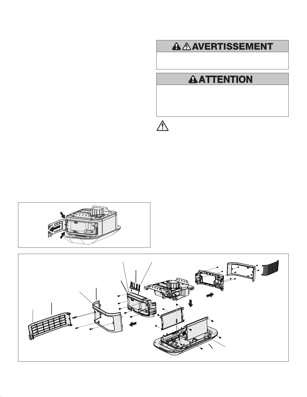
2. Retirez les portes en plastique et mettez-les dans un endroit sûr (gure A)
3. Retirez les couvercles des panneaux d’extrémité des deux côtés et
mettez-les dans un endroit sûr (gure B, élément B)
4. Retirez les 4 ou 6 vis des côtés selon le modèle
5. Retirez le module intégré d’éclairage à DEL de l’ouvre-porte (gure B,
élément E).
6. Débranchez le module intégré d’éclairage à DEL (et la caméra si
nécessaire) et mettez-les dans un endroit sûr
7. Retirez les 4 vis du panneau d’extrémité du côté de la carte mère (vis
non pointues) (gure B, élément C)
8. Retirez partiellement le panneau d’extrémité
9. Débranchez les connecteurs de ls de la carte mère (gure B, élément D)
10. Retirez complètement le panneau d’extrémité et mettez-le dans un
endroit sûr
11. Retirez les 4 vis de l’autre panneau d’extrémité et mettez-les dans un
endroit sûr
Pour éviter d’endommager le récepteur/la carte mère, ne touchez PAS
le circuit imprimé du récepteur/de la carte mère de remplacement
pendant l’installation.
Portez TOUJOURS des gants et des lunettes de protection
lorsque vous changez la batterie ou que vous travaillez autour du
compartiment de la batterie.
Pour éviter d’éventuelles BLESSURES GRAVES voire FATALES :
• Débranchez TOUTE l’alimentation électrique et la batterie AVANT
d’effectuer TOUT service ou entretien.
AVERTISSEMENT : Ce produit peut vous exposer à des produits
chimiques, dont le plomb, qui sont reconnus par l’État de
Californie comme provoquant le cancer, des malformations
congénitales ou d’autres problèmes de reproduction. Pour en
savoir plus, visitez www.P65Warnings.ca.gov.
12. Retirez les 2 dernière vis du châssis pour détacher le couvercle du
boîtier principal que vous devez remplacer
13. Remplacez le couvercle du boîtier principal
14. Remettez en place les panneaux d’extrémité des deux côtés en utilisant
4 vis de chaque côté (vis non pointues)
15. Branchez le module intégré d’éclairage à DEL (et la caméra si
nécessaire)
16. Rattachez le module à l’aide des 4 ou 6 vis enlevées à l’étape 4
17. Remettez en place les couvercles des panneaux d’extrémité en utilisant
4 vis de chaque côté (vis pointues)
18. Remettez en place les portes en plastique
19. Branchez l’ouvre-porte de garage et la batterie (le cas échéant)
Panneau de la porte
de commande
Couvercle du panneau d’extrémité
Panneau d’extrémité Connecteurs de fils de la carte mère
Module d’éclairage à DEL
FigureB
FigureA
A
B
C
D
E
© 2021, LiftMaster
All rights reserved
Tous droits réservés
Todos los derechos reservados
114-5583-000

Reemplazo del cerramiento principal
Piezas de repuesto 041-0190-000, 041-0191-000 y 041-0207-000
Instrucciones
Necesitará:
• Llave de tuerca magnética de 1/4"
• Pinza de punta
• Llave de tuerca magnética de cuello largo de 5/16" y vaso
• Destornillador plano
Las imágenes utilizadas en este manual son solo como referencia y su
producto puede verse diferente.
1. Desenchufe el abrepuertas de garaje y desconecte la batería (de ser
necesario)
2. Quite las puertas de plástico de ambos lados y colóquelas en un lugar
seguro (Figura A)
3. Quite la cubierta del panel del extremo de ambos lados y colóquelas en
un lugar seguro (Figura B, Ítem B)
4. Quite 4 o 6 tornillos de los lados según el modelo
5. Quite el módulo de la lámpara con LED integrado (Figura B, Ítem E)
6. Desenchufe el módulo de la lámpara con LED integrado (y la cámara de
ser necesario) y colóquelo en un lugar seguro
7. Quite 4 tornillos del panel lateral del extremo de la tarjeta lógica
(tornillos no puntiagudos) (Figura B, Ítem C)
8. Quite parcialmente el panel del extremo
9. Desconecte los conectores del cable de la tarjeta lógica (Figura B, Ítem D)
10. Quite por completo el panel del extremo y colóquelo en un lugar seguro
11. Quite los 4 tornillos del otro panel del extremo y colóquelos en un lugar
seguro
12. Quite los últimos 2 tornillos del chasis para desprender la cubierta del
cerramiento principal que reemplazará
Para evitar daños al receptor/tarjeta lógica, NO toque el circuito
impreso de la tarjeta en el receptor/tarjeta lógica de repuesto durante
la instalación.
Use SIEMPRE guantes protectores y protectores para la vista al
cargar la batería o al trabajar cerca del compartimento de la batería.
Para evitar posibles LESIONES GRAVES o la MUERTE:
• Desconecte TODA alimentación eléctrica y de batería ANTES de
realizar CUALQUIER servicio o mantenimiento.
ADVERTENCIA: Con este producto, puede exponerse a
sustancias químicas, incluido el plomo, que el Estado de
California reconoce como causantes de cáncer o anomalías
congénitas u otros daños reproductivos. Para obtener más
información, visite www.P65Warnings.ca.gov.
13. Reemplace la cubierta del cerramiento principal
14. Vuelva a colocar los paneles del extremo de ambos lados con 4 tornillos
de cada lado (tornillos no puntiagudos)
15. Enchufe el módulo de la lámpara con LED integrado (y la cámara de ser
necesario)
16. Vuelva a colocar el módulo con los 4 o 6 tornillos extraídos en el paso 4
17. Vuelva a colocar las cubiertas de los paneles del extremo con 4 tornillos
de cada lado (tornillos puntiagudos)
18. Vuelva a colocar las puertas de plástico
19. Enchufe el abrepuertas de garaje y la batería (de ser necesario)
Puerta del panel
de control
Cubierta del panel del extremo
Panel del extremo
Conectores de cable de la tarjeta lógica
Módulo de la lámpara LED
Figura B
Figura A
A
B
C
D
E
© 2021, LiftMaster
All rights reserved
Tous droits réservés
Todos los derechos reservados
114-5583-000