Loading ...
Loading ...
Loading ...

ADJ Products, LLC - www.adj.com - DMX Operator 384 User Manual Page 6
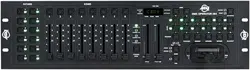
DMX Operator 384 Rear Panel Overview
5
3
2
4
1
Midi In
Midi Out
1=NC; 2=GND
3=NC; 4=V+
5=Signal
1=NC; 2=NC
3=NC; 4=V+
5=Signal
Made in PRC
DC input:
9V-12VDC, 500mA Min
1 2
5
4
63
8
7
9 10 11 12
5
3
2
4
1
Midi I n
Midi Ou t
1=NC; 2=GND
3=NC; 4=V+
5=Signal
1=NC; 2=NC
3=NC; 4=V+
5=Signal
Made in P.R.C.
Power
RoHS
DC In
DC input:
9V-12VDC, 500mA Min
DMX Out
FOG MachineMidi In Midi Out
DB-9
EXT Step Control
Audio
Line Input 0.1V-1Vp-p
USB
Serial Number:
1 = Ground
2 = Data -
3 = Data +
DMX O ut
DMX
Mid i
1. Label: Lists model, serial number, and production date.
2. Audio input: To connect line level input for audio trigger (0.1V-1Vp-p).
3. DB-9 connector: To connect optional external chase step controller.
NOTE: No longer included in units manufactured after Feb. 2018.
4. MIDI IN: To receive MIDI information from a midi sequencer or compatible device.
5. Fog machine connector: To connect a compatible fog machine.
6. 3 Pin Female XLR: DMX Output. Connect to rst device in line.
7. DC INPUT: Connects the included power supply to this input. (DC 9V~15V, 500mA Min).
8. Power switch: Used to switch the units power on and o.
9. USB Interface: Outputs the MIDI signal via USB interface when connected to MIDI controller.
10. LED Lamp: Indicates the working state of USB interface.
11. Switch: Switches the function of DMX controller or MIDI controller. The change will work after
re-startup.
12. MIDI Out Socket: output the MIDI signal when connected to the MIDI controller.
Loading ...
Loading ...
Loading ...