Loading ...
Loading ...
Loading ...
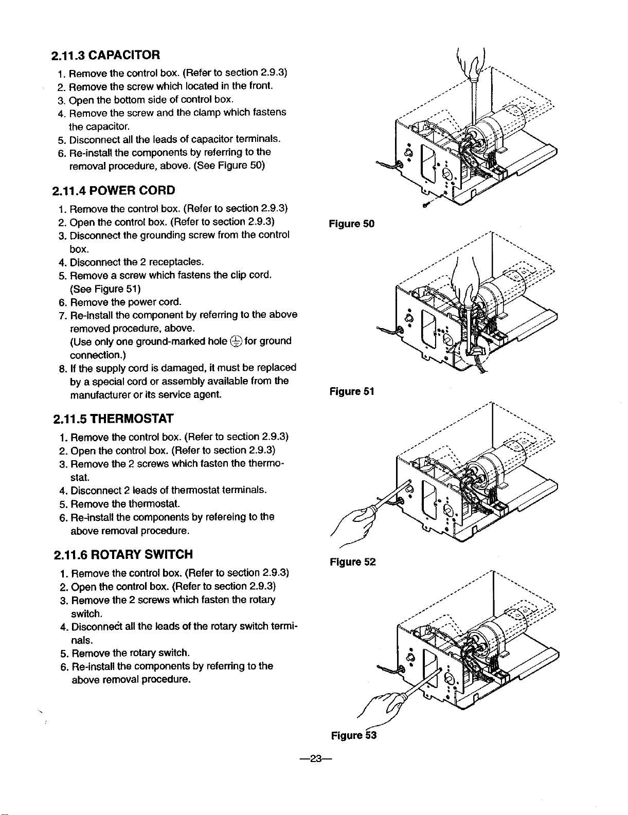
2.11.3 CAPACITOR
1. Remove the controlbox. (Refer to section 2.9,3)
2. Remove the screw which located in the front,
3. Open the bottom side of control box.
4. Remove the screw and the clamp which fastens
the capacitor.
5. Disconnect all the leads of capacitor terminals.
6. Re-instal! the components by referring to the
removal procedure, above. (See Figure 50)
2.11.4 POWER CORD
1. Remove the control box. (Refer to section 2.9.3)
2. Open the control box. (Refer to section 2.9.3)
3. Disconnect the grounding screw from the control
box.
4. Disconnect the 2 receptacles.
5. Remove a screw which fastens the clip cord.
(See Figure 51)
6. Remove the power cord.
7. Re-install the component by referring to the above
removed procedure, above.
(Use only one ground-marked hole (_ for ground
connection.)
8. If the supply cord is damaged, it must be replaced
by a special cord or assembly available from the
manufacturer or its service agent.
2.11.5 THERMOSTAT
1. Remove the control box. (Refer to section 2.9.3)
2. Open the control box. (Refer to section 2.9.3)
3. Remove the 2 screws which fasten the thermo-
stat.
4. Disconnect 2 leads of thermostat terminals.
5. Remove the thermostat.
6. Re-install the components by refereing to the
above removal procedure.
2.11.6 ROTARY SWITCH
1. Remove the control box. (Refer to section 2.9.3)
2. Open the control box. (Refer to section 2.9.3)
3. Remove the 2 screws which fasten the rotary
switch.
4. Disconnect all the leads ofthe rotaryswitch termi-
nals.
5. Remove the rotary switch.
6. Re-install the components by referring to the
above removal procedure.
Figure 50
Figure 51
Figure 52
Figure 53
--23--
Loading ...
Loading ...
Loading ...